3-2 5975978 RETRO GRAPHICS 2100 220198
Power Up Considerations
Ensure that the power switch is in the 'on-1' position on the rear
control panel and also ensure the internal mains power plug is in
place. The projector will not activate unless these two conditions are
correctly undertaken.
$8',2287
$8',2,1& $8',2,1%
$8',2,1$
9,'(2
9,'(2
69,'(2
5*%+&9
5*%+&9
/5 /5
/5 /5
,5
55
**
%%
+& +&
99
72/2&$/&21752/21/<
3257
3257
3257
3257
3257
56,1 56287 &2003257 &75/
hard wire remote
2KP:
/5
Internal mains connection
permanently connected
Internal power switch always to be
positioned in the
’1’
ON
state
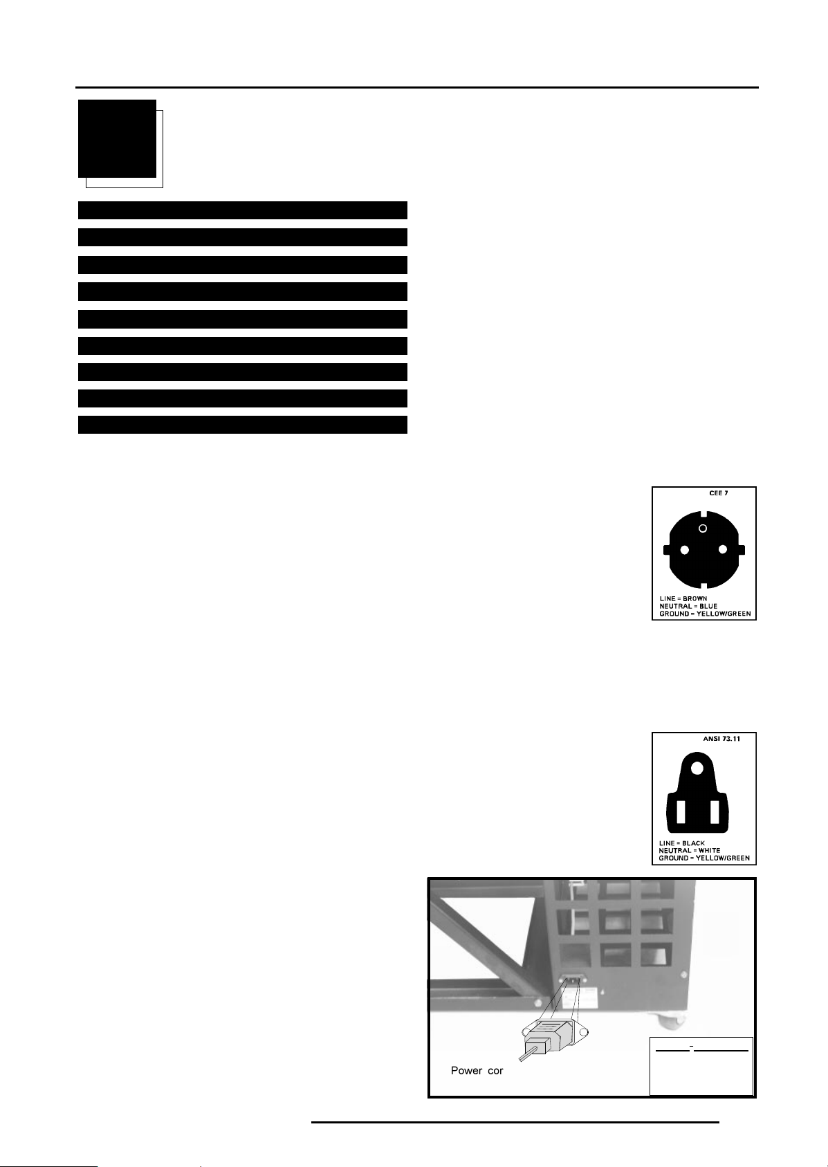
Input Power (mains) Voltage Alteration
Attention
The Retro Graphics 2100 - R9001310 leaves the factory to operate
on a mains (power) input of 230V AC. Alteration of the power input
of the projector from 230V AC to 120V AC, or vice versa is possible.
Follow the procedure as described below for alteration, it is recom-
mended that a qualified Barco technician performs the alteration.
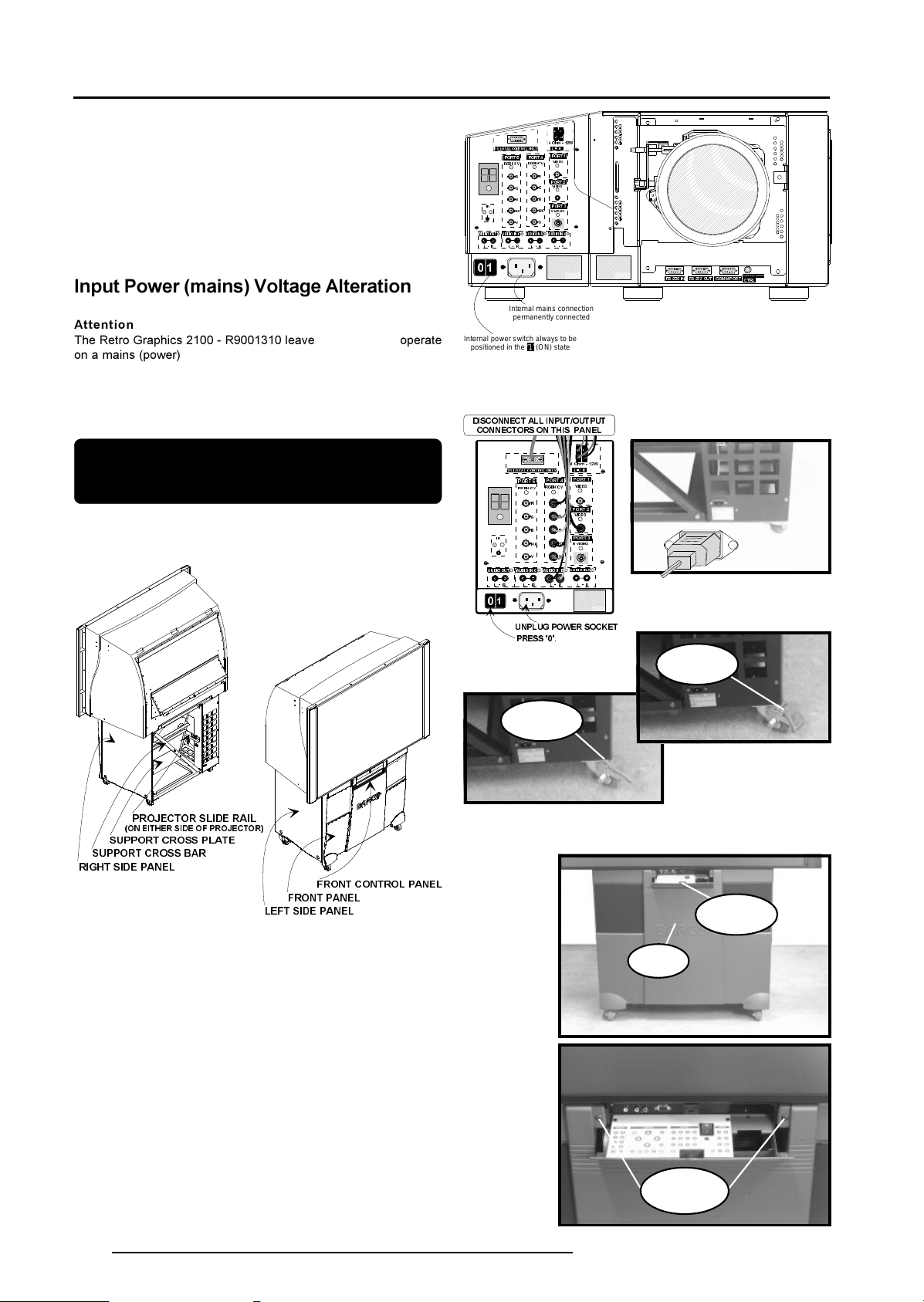
WARNING : Power down all devices and switch off, discon-
nect all the input/output connectors to the projector. Unplug
the power cord from the rear of the retro projector and lock
the retro projectors rear positioning wheels.
I
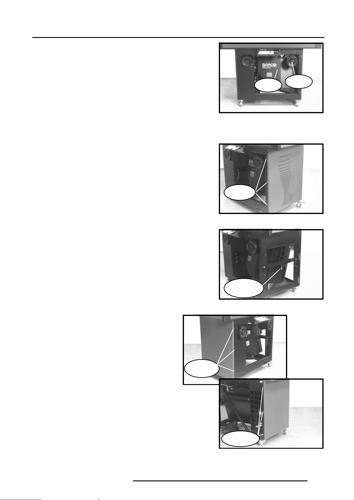
Removing the Projector
,a. The front panel needs to be removed and this is achieved by
firstly opening the front control panel and gaining access to the two
large locking screws on either side of the control panel. Unlock by
turning one half turn counter clockwise. The front panel can now be
released from its mountings by tilting forwards slightly, then lifting
upwards and outwards (the front control panel should remain in the
open position at all times.)
It will be necessary to remove the front, rightside and leftside
panelling, plus the associated strengthening supports of the lower
projector cabinet, by either loosening or removing their fixing nuts.
Tools Required
Phillips screw driver (PH0)
Flat Top Screw Driver
Wrench, Spanner (No- 7,8,10)
/()7
6,'(
3$1(/
)52173$1(/
)5217&21752/3$1(
6833257&5266%$5
6833257&52663/$7(
352-(&7256/,'(5$,/
21(,7+(56,'(2)352-(&725
5,*+7
6,'(
3$1(/
$8',2287 $8',2,1& $8',2,1% $8',2,1$
9,'(2
9,'(2
69,'(2
5*%+&9
5*%+&9
/5 /5
/5 /5
,5
55
**
%%
+& +&
9
9
72/2&$/&21752/21/<
3257
3257
3257
3257
3257
2KP:
/5
',6&211(&7$//,1387287387
&211(&7256217+,63$1(/
813/8*32:(562&.(7
35(66
WHEEL
POSITION LOCK
'OFF'
WHEEL
POSITION LOCK
'ON'
ê
PRESS
ý
þ
Disconnect
Power cord
û
POWER / M
9
a
FRONT
PANEL LOCKING
SCREWS
FRONT
PANEL
FRONT
CONTROL
PANEL