Barco MDSC-2242 User manual

MDSC-2242
User Guide
(451920611333)K5903030/02
09/10/2014

Barco nv
President Kennedypark 35, 8500 Kortrijk, Belgium
Phone: +32 56.23.32.11
Fax: +32 56.26.22.62
Support: www.barco.com/esupport
Visit us at the web: www.barco.com
PrintedinBelgium

Table of contents
TABLE OF CONTENTS
1. Welcome! .......................................................................................... 3
1.1 About the product ............................................................................................. 3
1.2 What’s in the box.............................................................................................. 3
1.3 About this user guide ......................................................................................... 4
2. Parts, controls and connectors ............................................................... 5
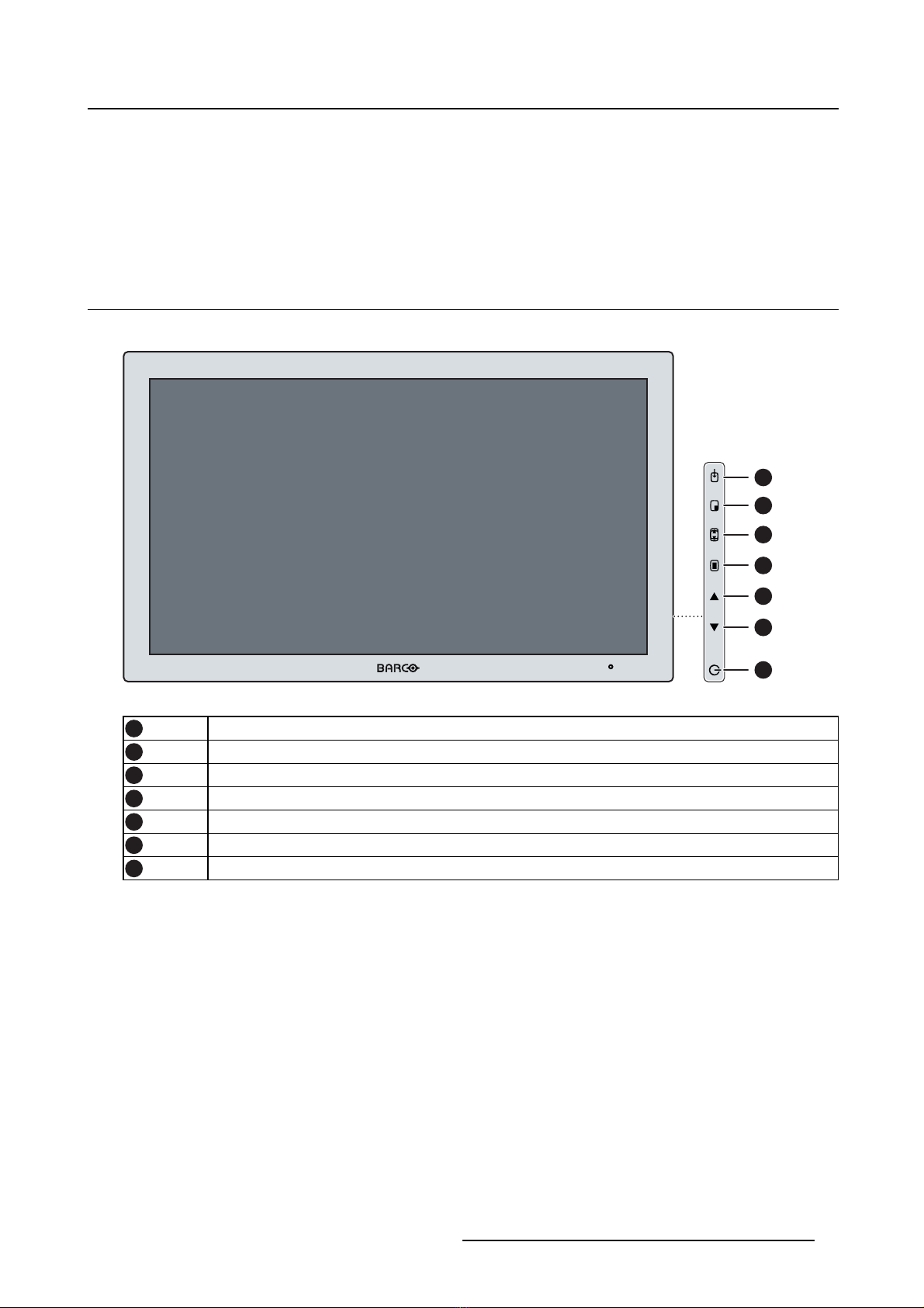
2.1 Front view...................................................................................................... 5
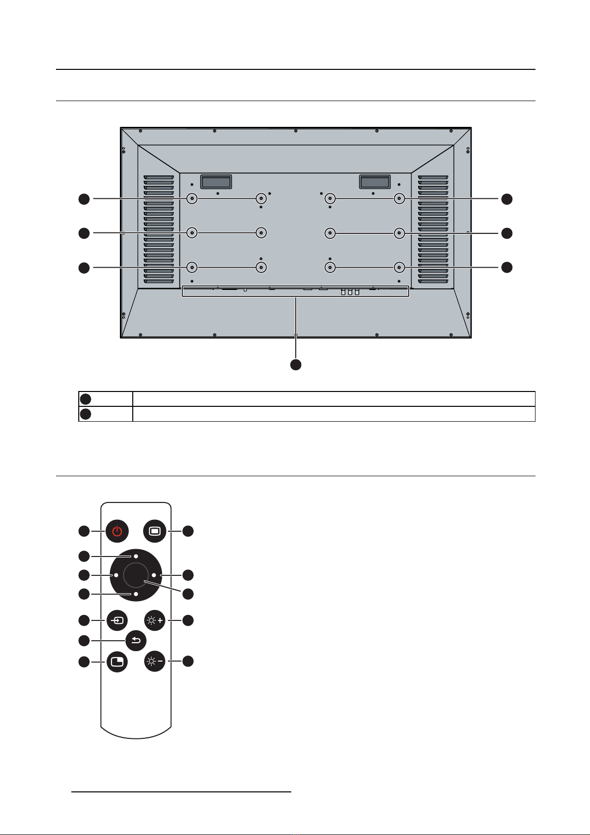
2.2 Rear view ...................................................................................................... 6
2.3 Remote control................................................................................................ 6
2.4 Connector view................................................................................................ 7
2.4.1 MDSC-2242 LED version............................................................................... 7
2.4.2 MDSC-2242 MNA version.............................................................................. 8
2.5 Connector pin assignments.................................................................................. 9
2.5.1 DVI–1 connector (DVI-I) ................................................................................ 9
2.5.2 DVI out connector (DVI-D) .............................................................................10
2.5.3 RS232 connector........................................................................................10
2.5.4 USB connector...........................................................................................11
2.5.5 DisplayPort connector ..................................................................................11
2.5.6 S-Video and S-Video-out connector...................................................................12
3. Display installation .............................................................................. 13
3.1 VESA mount installation......................................................................................13
3.2 Video input connection .......................................................................................14
3.2.1 MDSC-2242 LED version...............................................................................14
3.2.2 MDSC-2242 MNA version..............................................................................15
3.3 Video output connection......................................................................................15
3.3.1 MDSC-2242 LED version...............................................................................16
3.3.2 MDSC-2242 MNA version..............................................................................16
3.4 Nexxis OR .....................................................................................................17
3.5 Power supply connection.....................................................................................17
4. Daily operation ................................................................................... 19
4.1 On/Off switching...............................................................................................19
4.2 Power led status ..............................................................................................19
4.3 OSD menu activation.........................................................................................19
4.4 OSD menu navigation ........................................................................................20
4.5 Shortkey functions ............................................................................................21
4.5.1 Main source selection...................................................................................21
4.5.2 Multi-image configuration...............................................................................21
4.5.3 Zoom factor selection ...................................................................................22
4.5.4 Brightness adjustment ..................................................................................22
4.6 Keyboard locking/unlocking..................................................................................22
4.7 Remote control................................................................................................22
5. Advanced operation ............................................................................. 25
5.1 OSD picture menu ............................................................................................25
5.1.1 Profile.....................................................................................................25
5.1.2 Brightness................................................................................................25
5.1.3 Contrast ..................................................................................................26
5.1.4 Saturation ................................................................................................26
5.1.5 Color temperature.......................................................................................26
5.1.6 Gamma...................................................................................................27
5.1.7 Sharpness................................................................................................27
5.2 Picture Advanced menu......................................................................................28
5.2.1 Black Level...............................................................................................28
5.2.2 Smart Video..............................................................................................28
5.2.3 Image Position...........................................................................................28
5.2.4 Auto Adjustment.........................................................................................29
(451920611333)K5903030 MDSC-2242 09/10/2014 1

Table of contents
5.2.5 Phase.....................................................................................................29
5.2.6 Clock/Line................................................................................................29
5.3 Display Format menu.........................................................................................30
5.3.1 Main Source (Primary Source).........................................................................30
5.3.2 Component Mode .......................................................................................31
5.3.3 Zoom......................................................................................................31
5.3.4 Image Size ...............................................................................................31
5.3.5 2nd Picture Mode ........................................................................................32
5.3.6 2nd Picture Source.......................................................................................32
5.3.7 2nd Picture Position......................................................................................33
5.3.8 Picture Swap.............................................................................................33
5.4 Configuration menu...........................................................................................34
5.4.1 Information ...............................................................................................34
5.4.2 Language.................................................................................................34
5.4.3 Failover mode............................................................................................35
5.4.4 OSD setting ..............................................................................................35
5.4.4.1 OSD Horizontal Position ..........................................................................35
5.4.4.2 OSD Vertical Position .............................................................................35
5.4.4.3 OSD Time-out......................................................................................36
5.4.5 Recall Profile.............................................................................................36
5.4.6 Save Profile..............................................................................................36
5.5 System menu..................................................................................................37
5.5.1 Power on DVI 1..........................................................................................37
5.5.2 DVI Output ...............................................................................................37
5.5.3 Keyboard lock............................................................................................38
5.5.4 Power Saving............................................................................................38
6. Important information ........................................................................... 39
6.1 Safety information.............................................................................................39
6.2 Environmental information ...................................................................................41
6.3 Biological hazard and returns................................................................................43
6.4 Regulatory compliance information .........................................................................44
6.5 Cleaning and disinfection ....................................................................................44
6.6 Explanation of symbols.......................................................................................45
6.7 Legal disclaimer...............................................................................................47
6.8 Technical specifications ......................................................................................47
6.9 Open source license information............................................................................52
2(451920611333)K5903030 MDSC-2242 09/10/2014

1. Welcome!
1. WELCOME!
1.1 About the product
Overview
Barco’s MDSC-2242 is a 42-inch surgical display. Purpose-built for the operating room, the MDSC-2242
offers an easy-clean design, smart mechanics and the most detailed images in the operating room today.
Ease of mind
The MDSC-2242 comes with a smart cable management system. The design allows easy mounting on
arms/suspension system. Available in two models, this surgical display also features a host of connectivity
options and remote control.
Ease of installation
The MDSC-2242 comes with a smart cable management system. Its lightweight design allows easy
mounting on surgical booms and spring arms. Available in two models, this surgical display also fea-
tures a host of connectivity options and remote control.
Ease of use
Barco’s MDSC-2242 allows easy cleaning and complete disinfection thanks to its smooth surface and
protective screen glass. The fanless design avoids the spread of contaminants (valid for the MDSC-2242
LED only).
Features
• 42-inch wide-screen LCD with full HD resolution and 10–bit per color
• Wide viewing angle
• High-brightness LED backlight
• Advanced, full 10-bit image processing algorithms with 12–bit LUT
• Widest range of SD and HD input signals, including 3G-SDI and DisplayPort
• Light weight to easily mount onto a boom
Innovative features are also available to give maximum flexibility when installing the display as: Config-
urable DVI-out and Failover Mode
1.2 What’s in the box
Overview
Your MDSC-2242 display comes with:
• MDSC-2242 user guide
•DVIcable
• AC power cords
•12screws
• Remote control
• 1 CR2032 Remote control battery
(451920611333)K5903030 MDSC-2242 09/10/2014 3

1. Welcome!
Keep your original packaging. It is designed for this display and is the ideal protection
during transport.
1.3 About this user guide
Overview
This manual provides a support to the user during the installation, set up and utilization of the MDSC-2242
display. Depending on the specific version that has been purchased, some of the features and options
described in this document may not apply to the display in user’s hands.
4(451920611333)K5903030 MDSC-2242 09/10/2014

2. Parts, controls and connectors
2. PARTS, CONTROLS AND
CONNECTORS
2.1 Front view
Overview
7
6
5
4
3
2
1
Image 2-1
1Input Selection key
2Multi-image selection key / Down key
3Image zoom key / Up key
4OSD Menu key / Enter key
5Brightness decrease / Left key
6Brightness increase / Right key
7Stand-by key
A 7-key keypad is located on the right side of the display.
(451920611333)K5903030 MDSC-2242 09/10/2014 5

2. Parts, controls and connectors
2.2 Rear view
Overview
1
1
1
1
1
1
2
Image 2-2
1VESA mount screw holes
2Connector location
2.3 Remote control
Overview
OK
1
9
6
2
11
10
8
5
4
3
12
7
Image 2-3
6(451920611333)K5903030 MDSC-2242 09/10/2014

2. Parts, controls and connectors
1Standby (On/Off)
2OSD menu (Enter/Exit)
3Up (Zoom +)
4Left
5Down
6Right
7Ok (Select)
8Input Selection
9Brightness +
10 Back
11 PiP Swap
12 Brightness -
2.4 Connector view
2.4.1 MDSC-2242 LED version
Overview
1 2 3 4 5 6 7
8 9 10
11 12 13
14
15 17
16
Image 2-4
1Mains input
2Earth
3SDI-1 out
4SDI-1 in
5DVI out
6DVI-1 in
7Display Port in
8Sync/Cr in
9CVBS/Y in
10 CVBS out
11 R/Pr
12 G/Y/SOG
13 B/Pb
14 S-Video out
15 S-Video
16 RS232 in
17 Service
(451920611333)K5903030 MDSC-2242 09/10/2014 7

2. Parts, controls and connectors
2.4.2 MDSC-2242 MNA version
Overview
1
2
3 5 11 13 14
15 16 17
18 19 20
21
22 24
234
6 7
8
9
10 12
Image 2-5
1Mains Input
2Earth
3Optical 10Gb Ethernet SFP+ interface*
4LED2*
Orange blinking: Activity = (Tx) or (Rx)
Off: No network activity
5LED1*
Green: Link is active
Off: No active network connection
6Cap
7LED3*
Green: Power on, normal operation
Off: System not powered
Orange blinking: Error
8Micro USB interface*
9USB 2.0 type A interface*
10 Cap
11 DVI out
12 Cap
13 DVI-1 in
14 DisplayPort (VESA std 1.1a)
15 Sync/Cr in
16 CVBS/Y in
17 CVBS out
18 R/Pr
19 G/Y/SOG
20 B/Pb
21 S-Video out
22 S-Video in
23 RS232 in
24 Service
(*) Nexxis OR functionality: for more detailed information please refer to the dedicated user guides. Please
visit www.barco.com to obtain these user guides.
8(451920611333)K5903030 MDSC-2242 09/10/2014

2. Parts, controls and connectors
2.5 Connector pin assignments
2.5.1 DVI–1 connector (DVI-I)
Overview
Image 2-6
Pin Function
1D2_Rx- (T.M.D.S.)
2D2_Rx+ (T.M.D.S.)
3GND (data 2 shield)
4 Not connected
5 Not connected
6SCL (for DDC)
7SDA (for DDC)
8 Analog vertical sync
9D1_Rx- (T.M.D.S.)
10 D1_Rx+ (T.M.D.S.)
11 GND (data 1 shield)
12 Not connected
13 Not connected
14 +5V input (DDC supply) (*)
15 GND (cable sense)
16 Hotplugdetect(*)
17 D0_Rx- (T.M.D.S.)
18 D0_Rx+ (T.M.D.S.)
19 GND (data 0 shield)
20 Not connected
21 Not connected
22 GND (clock shield)
23 CK_Rx+ (T.M.D.S.)
24 CK_Rx- (T.M.D.S.)
C1 Analog Red
C2 Analog Green
C3 Analog Blue
C4 Analog horizontal sync
C5 Analog GND return (analog R, G, B)
(*) +5 VDC output selectable on either pin 14 or 16 via the OSD menu. (+5V ± 10% @ 500mA (max))
PC analog (VGA) input source can be connected to the DVI-I input connector using a
DVI-I to VGA adapter. The use of an adapter cable of at least 0.15 m long will allow an
easy placement inside the cable cover.
(451920611333)K5903030 MDSC-2242 09/10/2014 9

2. Parts, controls and connectors
2.5.2 DVI out connector (DVI-D)
Overview
Image 2-7
Pin Function
1D2_Rx- (T.M.D.S.)
2D2_Rx+ (T.M.D.S.)
3GND (data 2 shield)
4 Not connected
5Not connected
6SCL (for DDC)
7SDA (for DDC)
8 Not connected
9D1_Rx- (T.M.D.S.)
10 D1_Rx+ (T.M.D.S.)
11 GND (data 1 shield)
12 Not connected
13 Not connected
14 +5V output (*)
15 GND (cable sense)
16 Hot plug detect
17 D0_Rx- (T.M.D.S.)
18 D0_Rx+ (T.M.D.S.)
19 GND (data 0 shield)
20 Not connected
21 Not connected
22 GND (clock shield)
23 CK_Rx+ (T.M.D.S.)
24 CK_Rx- (T.M.D.S.)
(*) +5 VDC output always available. (+5V ± 10% @ 500mA (max))
2.5.3 RS232 connector
Overview
Image 2-8
Pin Function
1 Not connected
2 Rx (driven by host)
3 Tx (driven by display)
10 (451920611333)K5903030 MDSC-2242 09/10/2014

2. Parts, controls and connectors
4 Not connected
5Ground
6 Not connected
7Not connected
8 Not connected
9 Not connected
2.5.4 USB connector
Overview
Image 2-9
Pin Function
1+5 VDC
2Data—
3Data+
4GND
2.5.5 DisplayPort connector
Overview
19 17 15 13 11 9 7 5 3 1
20 18 16 14 12 10 8 6 4 2
Image 2-10
Pin Function
1ML_Lane 0 (p)
2GND
3ML_Lane 0 (n)
4ML_Lane 1 (p)
5GND
6ML_Lane 1 (n)
7ML_Lane 2 (p)
8GND
9ML_Lane 2 (n)
10 ML_Lane 3 (p)
11 GND
12 ML_Lane 3 (n)
13 CONFIG1
14 CONFIG2
15 AUX CH (p)
16 GND
17 AUX CH (n)
(451920611333)K5903030 MDSC-2242 09/10/2014 11

2. Parts, controls and connectors
18 Hot Plug
19 Return
20 DP_PWR (+3.3 VDC)
2.5.6 S-Video and S-Video-out connector
Overview
Image 2-11
Pin Function
1Ground (Y)
2Ground (C)
3Luminance (Y)
4Chroma (C)
SG Shielded Ground
12 (451920611333)K5903030 MDSC-2242 09/10/2014

3. Display installation
3. DISPLAY INSTALLATION
3.1 VESA mount installation
Overview
The display supports arm stands according to the VESA 600 mm & 200 mm standard.
CAUTION:Use an arm/suspension system that is approved by VESA.
CAUTION:The monitor VESA interface has been designed for a safety factor 6 (to sup-
port 6 times the monitor weight). In the medical system, use an arm with suitable safety
factor (IEC60601–1).
To mount the display to an arm stand
1. Attach the arm stand firmly to the arm/suspension system using the 6 screws (M6 x 12 mm) related to
the VESA standard used (VESA 200mm or 600mm).
600mm VESA
200mm VESA
200mm VESA
Image 3-1
CAUTION:The 12 screws included with this display (M6 x 12 mm) can be used for an
external VESA arm/suspension interface with a thickness of up to 4 mm.
If, due to the thickness of the external VESA arm interface (=V), the length of the provided
screws (=L) is not suitable, consider the following rule:
Lmin =V+8mm
Lmax =V+15mm
(451920611333)K5903030 MDSC-2242 09/10/2014 13

3. Display installation
WARNING:The IP protection rating of the display is guaranteed only if the 12 VESA
holes are closed (e.g. using the screws provided with the display).
3.2 Video input connection
WARNING:When the display is assembled in the medical system, take care of the fixa-
tion of all cables, to avoid unwanted detachment.
About video input connections
The MDSC-2242 can have multiple different video inputs connected (depending on the display version).
Switching between the different inputs can be easily done by pressing the direct access key for this. See
the dedicated section for more info.
Futhermore, if more than one video source is connected, the Picture in Picture (PiP) and Side-by-Side
(SbS) functionality becomes available, allowing you to view two different video inputs at once. Please
refer to the dedicated chapter for more info on how to activate and use the PiP and SbS features on your
MDSC-2242.
This chapter describes how to connect the different video input types for each version of the MDSC-2242.
3.2.1 MDSC-2242 LED version
To connect the video inputs
1. Connect one or more of the available video source(s) to the corresponding video inputs using the ap-
propriate video cable(s).
1
2 3
4 5 6 7 8 9
Image 3-2
DVI or VGA (*) 4
DisplayPort 5
SDI 1
R/G/B/S 6/7/8/2
R/G/B (SOG) 6/7/8
Y/Pb/Pr 7/8/6
14 (451920611333)K5903030 MDSC-2242 09/10/2014

3. Display installation
CVBS 3
S-Video 9
(*) PC analog (VGA) input source can be connected to the DVI-I input connector using a DVI-I to VGA
adapter. The use of an adapter cable of at least 0.15 m long will allow an easy placement inside the cable
cover.
3.2.2 MDSC-2242 MNA version
To connect the video inputs
1. Connect one or more of the available video source(s) to the corresponding video inputs using the ap-
propriate video cable(s).
4 5 6 7 8
2 3
91
Image 3-3
Nexxis 1
DVI or VGA (*) 4
DisplayPort 5
R/G/B/S 6/7/8/2
Y/Pb/Pr 7/8/6
CVBS 3
S-Video 9
(*) PC analog (VGA) input source can be connected to the DVI-I input connector using a DVI-I to VGA
adapter. The use of an adapter cable of at least 0.15 m long will allow an easy placement inside the cable
cover.
3.3 Video output connection
WARNING:When the display is assembled in the medical system, take care of the fixa-
tion of all cables, to avoid unwanted detachment.
About video output connections
Beside the video input connections, the MDSC-2242 also has video output capabilities allowing you to
loop-through certain video inputs connected with the MDSC-2242 to another display, projector, video
recorder, ...
(451920611333)K5903030 MDSC-2242 09/10/2014 15

3. Display installation
This chapter describes how to make use of the video output connections available for each version of the
MDSC-2242.
3.3.1 MDSC-2242 LED version
To connect the video outputs
1. Connect one or more of the available video sink(s) to the corresponding video outputs using the appro-
priate video cable(s).
4
1
2 3
Image 3-4
SDI 1
CVBS 2
S-Video 3
DVI 4(tobeconfiguredinOSDmenu)
3.3.2 MDSC-2242 MNA version
To connect the video outputs
1. Connect one or more of the available video sink(s) to the corresponding video outputs using the appro-
priate video cable(s).
2 3
1
Image 3-5
DVI 1(tobeconfiguredinOSDmenu)
Nexxis 1(tobeconfiguredinOSDmenu)
16 (451920611333)K5903030 MDSC-2242 09/10/2014

3. Display installation
CVBS 2
S-Video 3
3.4 Nexxis OR
Overview
Connecting your MDSC-2242 to Barco’s Nexxis OR system allows you to distribute video, graphics, audio
and computer data over the IP network, in raw uncompressed format, inside the operating room and even
between surgical suites.
To connect your MDSC-2242 to Barco’s Nexxis OR system, connect the 10Gb Ethernet interface to your
Nexxis switch. More info about Nexxis OR and how to configure the MDSC-2242 in your network is avail-
able in the dedicated user guides. Please visit www.barco.com to obtain these user guides.
Nexxis OR is only available on the MDSC-2242 MNA version.
3.5 Power supply connection
WARNING:When the display is assembled in the medical system, take care of the fixa-
tion of all cables, to avoid unwanted detachment.
To connect the power supply & protective earth pin
1. Connect the power input of your MDSC-2242 display into a grounded power outlet by means of the
proper power cord delivered in the packaging.
2
1
Image 3-6
2. The MDSC-2242 display is provided with an additional protective earth pin, if necessary connect the
earth pin to a grounded outlet by means of an AWG18 (max. 6ft / 1,8m long) wire.
(451920611333)K5903030 MDSC-2242 09/10/2014 17

3. Display installation
18 (451920611333)K5903030 MDSC-2242 09/10/2014
Other manuals for MDSC-2242
2
Table of contents
Other Barco LCD TV manuals
Popular LCD TV manuals by other brands

Currys Essentials
Currys Essentials C16LDVB11 instruction manual

Sharp
Sharp LC-70LE835E/RU Service manual

Sony
Sony KDL-40S5100 Instuctions operating instructions

CONTINENTAL EDISON
CONTINENTAL EDISON 19SD3 operating instructions

Philips
Philips 47PFL7603D - annexe 1 Specification sheet

JVC
JVC LT-32SH6/A Service manual