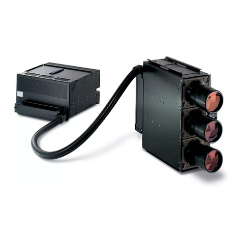
Barco OVERVIEW D 50" User manual

Installation manual
OVERVIEW D 50"

Title: Installation manual OVERVIEW MDG50-DL/OVERVIEW MDR50-DL / OVERVIEW MDR+50
Date: Septembe 2006
P odID: doc-3303-5
Rev: 10
This manual is divided into 11 chapte s:
main
issue
update
chapter 1
chapter 2
chapter 3 Rev. 10 seamless sc een added
chapter 4 Rev. 04: ea thquake p otection kit added,
chapter 5 Rev. 08: wall fixation added
chapter 6 Rev. 10 installation of 3200 colo filte
chapter 7
chapter 8
Chapter9
Chapter10
Chapter11 Revision 10 deinstallatin of seamless sc een
new: The co esponding chapte s a e new o completely evised.
co .: Passages of the co esponding chapte we e co ected; see modification ba s.
add.: Passages of the co esponding chapte we e added; see modification ba s.

1. Assembly of suppo t f ame
Barco – OverView D 50" – DOC-3303-5 – installation manual – Revision 10 – September 006 _____________________________________________________________ 1-1
Table of contents
1 Assembly of support frame ............................................................................................................... 1-1
1.1 Contents of suppo t f ame ca ton...............................................................................................................1-2
1.2 Requi ed tools..............................................................................................................................................1-3
1.3 Assembly of left and ight f ame ...............................................................................................................1-3
1.4 Installation of ho izontal p ofiles................................................................................................................1-4
2 et up of OverView mD...................................................................................................................... 2-1
2.1 Set up of Suppo ting F ame ........................................................................................................................2-2
2.2 Set up of Da k Boxes ...................................................................................................................................2-4
2.3 Installation of Safety B ackets ....................................................................................................................2-8
2.4 G ounding of the st uctu e..........................................................................................................................2-9
2.5 Pick up the p otective foil of the mi o .................................................................................................. 2-10
3 Installation of creen Module............................................................................................................ 3-1
3.1 Installation of the standa d sc een module ...............................................................................................3-1
3.2 Installation of the seamless sc een module ..............................................................................................3-4
4 Additional fixation facilities of systems employed with earthquake protection............................. 11
4.1.1 Fixation to the suppo t o to the adjacent da k box of the p evious ow, espectively. .................11
4.1.2 Fixation of the sc een f ame...............................................................................................................12
5 Wall fixation........................................................................................................................................ 13
6 Installation of Projection ystem ...................................................................................................... 6-1
6.1 Installation of Illumination Unit ..................................................................................................................6-2
6.2 Installation of P ojection Unit .....................................................................................................................6-5
6.3 Installation of the 3200K colo filte ca t idge...........................................................................................6-8
6.4 Cabling ...................................................................................................................................................... 6-11
6.5 Inse ting the Lamp Modules (Illumination unit with lamps of 100W/120W)....................................... 6-12
6.6 Inse ting the Lamp Modules (Illumination unit with lamps of 200W) .................................................. 6-13
6.7 Selecting the co ect lamp d ive ............................................................................................................ 6-14

1. Assembly of suppo t f ame
Barco – OverView D 50" – DOC-3303-5 – installation manual – Revision 10 – September 006 _____________________________________________________________ 1-
7 Optical Adjustment ............................................................................................................................ 7-1
7.1 The p ojection lens fo SXGA systems ........................................................................................................7-2
7.2 The p ojection lens fo XGA systems..........................................................................................................7-3
7.3 St ictly p ohibited devices...........................................................................................................................7-4
7.4 Adjustment devices.....................................................................................................................................7-5
7.5 Fi st steps.....................................................................................................................................................7-6
7.6 Focus adjustment ........................................................................................................................................7-6
7.7 Pictu e size...................................................................................................................................................7-7
7.8 Ve tical T apezoid ........................................................................................................................................7-8
7.9 Ho izontal t apezoid ....................................................................................................................................7-9
7.10 Rotation .................................................................................................................................................. 7-10
7.11 Ho izontal pictu e shift........................................................................................................................... 7-11
7.12 Ve tical pictu e shift ............................................................................................................................... 7-12
7.13 Locking the P ojection Unit .................................................................................................................... 7-12
8 Final Adjustment and Configuration ................................................................................................. 8-1
8.1 The IR Remote-Cont ol Unit ........................................................................................................................8-1
8.1.1 Te minology of RCU cont ols ..............................................................................................................8-2
8.2 Gene al.........................................................................................................................................................8-3
8.3 Menu Layout................................................................................................................................................8-3
8.3.1 Navigating...........................................................................................................................................8-3
8.4 Activating the Menu Ba .............................................................................................................................8-3
8.4.1 Reset Runtime ....................................................................................................................................8-3
8.4.2 Lamp Optimization .............................................................................................................................8-4
8.5 Access to the se vice menu ........................................................................................................................8-6
8.5.1 P ojecto Add ess................................................................................................................................8-7
8.5.2 RS232 baud ate ..................................................................................................................................8-9
8.5.3 Inte nal patte ns .............................................................................................................................. 8-10
8.5.4 Colo /B ightness.............................................................................................................................. 8-12
8.5.5 O ientation ....................................................................................................................................... 8-26
8.5.6 Maintenance .................................................................................................................................... 8-27
8.5.7 No Sou ce Counte ........................................................................................................................... 8-32
8.5.8 I2C Diagnostics................................................................................................................................. 8-33
8.5.9 Dimme Senso Powe ..................................................................................................................... 8-34
8.5.10 Save................................................................................................................................................ 8-35
8.5.11 F eeze............................................................................................................................................. 8-36
8.5.12 Disable IR ....................................................................................................................................... 8-37
8.5.13 Lamps............................................................................................................................................. 8-38
8.5.14 Ve sion ........................................................................................................................................... 8-42

1. Assembly of suppo t f ame
Barco – OverView D 50" – DOC-3303-5 – installation manual – Revision 10 – September 006 _____________________________________________________________ 1-3
8.5.15 Mo e ............................................................................................................................................... 8-43
9 Updating projectors to Firmware 2.0 ................................................................................................ 9-1
9.1 Update p ocedu e........................................................................................................................................9-1
10 Manual User Interface ...................................................................................................................10-1
10.1.1 Powe Switch ................................................................................................................................. 10-1
10.1.2 Standby Switch .............................................................................................................................. 10-2
10.1.3 Active Lamp Selection Switch ....................................................................................................... 10-3
10.1.4 Indication of Powe LED ................................................................................................................ 10-4
10.1.5 Indication of Lamp Doo LED ......................................................................................................... 10-4
10.1.6 Indication of the Status LEDs......................................................................................................... 10-5
11 De-mounting the seamless screens .............................................................................................. 11-1

1. Assembly of suppo t f ame
OverView D 50" – DOC-3303-5 – installation manual – Revision 10 – September 006
September 006 September 006
September 006 ________________________________
________________________________________________________________
_________________________________________________________
__________________________________________________
_________________________1-1
1Assembly of support frame
In delive ies fo ove sea destination the suppo ts a e completely disassembled
This section desc ibes how to assemble the suppo t f ame fo Ove View mD.

1. Assembly of suppo t f ame
OverView D 50" – DOC-3303-5 – installation manual – Revision 10 – September 006
September 006 September 006
September 006 ________________________________
________________________________________________________________
_________________________________________________________
__________________________________________________
_________________________1-
1.1 Contents of support frame carton
Befo e sta ting to assemble the suppo t f ame check if the mate ial is complete.
Quantity
QuantityQuantity
Quantity
Desc
DescDesc
Desc iption
iption iption
iption
Suppo t
Suppo tSuppo t
Suppo t
875mm
875mm875mm
875mm
Suppo t
Suppo tSuppo t
Suppo t
1000mm
1000mm1000mm
1000mm
Suppo t
Suppo tSuppo t
Suppo t
1200mm
1200mm1200mm
1200mm
2 F ont p ofile ( ve tical ) PU I 1, PU I 2 PU 4I 1, PU 41 2 PU 3I 1, PU 31 2
2 Rea p ofile ( ve tical ) PU II 4, PU II 5 PU 4I 4, PU 4I 5 PU 3I 4, PU 3I 5
2 F ont p ofile ( ho izontal) PU II 3 PU 2I 12, PU II 3 PU 2I 12, PU II 3
2 Rea p ofile ( ho izontal ) PU II 3 PU II 3 PU II 3
4 Side p ofile PU I 7
PU I 7PU I 7
PU I 7 PU I 7
PU I 7PU I 7
PU I 7 PU I 7
PU I 7PU I 7
PU I 7
1 Angle with multi socket installed [2]
[2][2]
[2]
12 Reinfo cing angle [1]
[1][1]
[1]
1 Box with sc ews
4 Adjustable foot
4 P ofile connecto
1 Cable channel
2 safety b acket
Table 1
List of Contents 1 suppo t f ame
Figu e 1-1
Ove view of suppo t f ame, labels efe to suppo t 875mm, fo othe othe heights see table!

1. Assembly of suppo t f ame
OverView D 50" – DOC-3303-5 – installation manual – Revision 10 – September 006
September 006 September 006
September 006 ________________________________
________________________________________________________________
_________________________________________________________
__________________________________________________
_________________________1-3
1.2 Required tools
Quantity
QuantityQuantity
Quantity
Desc iption
Desc iption Desc iption
Desc iption
1 To x key size 30
1 Allen key size 6
Table 2
List of equi ed tools
1.3 Assembly of left and right frame
The following pictu e shows how to assemble both f ames.
Figu e 1-2
One of the p ofiles PU I 7 is equipped with 3 mo e counte nuts than the othe . This p ofile must be installed at
the ight side of the suppo t f ame ( ea view).
It is ve y impo tant that the p ofiles fit exactly togethe . The following figu e shows details.
Figu e 1-3

1. Assembly of suppo t f ame
OverView D 50" – DOC-3303-5 – installation manual – Revision 10 – September 006
September 006 September 006
September 006 ________________________________
________________________________________________________________
_________________________________________________________
__________________________________________________
_________________________1-4
1.4 Installation of horizontal profiles
•Install the two ho izontal p ofiles PU II 3 at the p ofiles PU I 2 and PU II 4
Figu e 1-4
•Tu n the suppo t that the two p ofiles PU II 3 touch the g ound.
•Install the second f ame at the p ofiles PU II 3.
Figu e 1-5

1. Assembly of suppo t f ame
OverView D 50" – DOC-3303-5 – installation manual – Revision 10 – September 006
September 006 September 006
September 006 ________________________________
________________________________________________________________
_________________________________________________________
__________________________________________________
_________________________1-5
•Inse t the two lowe panels.
Figu e 1-6
The panels must be tightened by secu ing sc ews and joined by ivets (see Figu e 1-6).
•Install both top p ofiles PU II 3. One of these p ofiles is equipped with 3 mo e counte nuts than the othe .
This p ofile must be installed at the f ont of the suppo t f ame between the p ofiles
PU I I and PU I 2.
Figu e 1-7

1. Assembly of suppo t f ame
OverView D 50" – DOC-3303-5 – installation manual – Revision 10 – September 006
September 006 September 006
September 006 ________________________________
________________________________________________________________
_________________________________________________________
__________________________________________________
_________________________1-6
•Install the multi socket angle (position see Figu e 1-1 [2])
The po er strip includes 6xIEC 320 sockets and is rated for a max. current of 10A.
Al ays take care that the max. rating of the po er strip is not exceeded!
In case the installation site is in a 110V country, and in case the display all is higher than
3 ro s, an additional po er strip has to be installed.
Of course the t o po er strips may not be connected in serie!
In 110V countries, at max. 3 darkboxes may be connected to a po er strip!
In case a second powe st ip is equi ed, p oceed as follows:
•De-mount the powe st ip attached to the multi socket angle.
•Unpack the second powe st ip: it is al eady attached to the metal base plate.
•Fix the de-mounted powe st ip to the metal base plate of the second powe st ip.
•Attach the metal base plate to the angle b acket.
The following pictu e sequence shows the p ocedu e stept by step:

1. Assembly of suppo t f ame
OverView D 50" – DOC-3303-5 – installation manual – Revision 10 – September 006
September 006 September 006
September 006 ________________________________
________________________________________________________________
_________________________________________________________
__________________________________________________
_________________________1-7
•Install the multi socket angle (position see Figu e 1-1 [2])
Figu e 1-8
•Install the einfo cing b ackets ( see Figu e 1-1 [1]). If the suppo t is highe than 875 mm these b ackets
look diffe ent, but the install p ocedu e is exactly the same.
Figu e 1-9
Installation of einfo cing angle

1. Assembly of suppo t f ame
OverView D 50" – DOC-3303-5 – installation manual – Revision 10 – September 006
September 006 September 006
September 006 ________________________________
________________________________________________________________
_________________________________________________________
__________________________________________________
_________________________1-8
Figu e 1-10
•Inse t the adjustable feet.
Figu e 1-11

1. Assembly of suppo t f ame
OverView D 50" – DOC-3303-5 – installation manual – Revision 10 – September 006
September 006 September 006
September 006 ________________________________
________________________________________________________________
_________________________________________________________
__________________________________________________
_________________________1-9
Figu e 1-12
Rea view of complete suppo t f ame
Figu e 1-13
F ont view of complete suppo t f ame

2. Set up of Ove View mD
OverView D 50" – DOC-3303-5 – installation manual – Revision 10 – September 006
September 006 September 006
September 006 ________________________________
________________________________________________________________
_________________________________________________________
__________________________________________________
_________________________ -1
2et up of OverView mD
This section desc ibes the set up of Ove View mD
Two enginee s a e equi ed to set up the system.
The oom in which the installation is ca ied out should al eady have been cleaned.
The set up comp ises the following steps:
•Installation of suppo ting f ame.
•Installation of da k-boxes.
•Installation of sc een module.
•Installation of illumination unit
•Installation of p ojection unit
•Optical adjustment

2. Set up of Ove View mD
OverView D 50" – DOC-3303-5 – installation manual – Revision 10 – September 006
September 006 September 006
September 006 ________________________________
________________________________________________________________
_________________________________________________________
__________________________________________________
_________________________ -
2.1 et up of upporting Frame
The following tools a e equi ed to set up the suppo ting f ame:
Size 5 and 6 hexagon keys.
Size 12 and 13 fo k w enches.
Size 10-socket spanne .
P ecision spi it level.
P oceed as follows to set up a linea a angement:
Positions of
adjustable feet
Front side
Back side
12
34
Figu e 2-1
adjustable feet
•Unpack suppo ting f ame, sc ew in the adjustable feet as fa as possible, and position f ames at equi ed
place.
•Adjust the suppo ting f ame.
Using the adjustable feet 1 and 2, fi st adjust the f ont axis of the fi st suppo ting f ame exactly ho izontally
(use p ecision spi it level). Secu e feet using counte nuts.
Subsequently align the depth axis exactly ho izontally using adjustable feet 3 and 4. Also secu e the feet
using counte nuts.
Once the suppo ting f ame has been aligned, unsc ew the feet 5 and 6 until they suppo t the load. Ca efully
check that the alignment of the suppo ting f ame is not changed in the p ocess (check using spi it level).
Fi st adjust suppo ting f ame 1, and then align and adjust the adjacent f ames with espect to this.
•Attach the suppo ting f ames to the floo via the lowe ancho ing devices

2. Set up of Ove View mD
OverView D 50" – DOC-3303-5 – installation manual – Revision 10 – September 006
September 006 September 006
September 006 ________________________________
________________________________________________________________
_________________________________________________________
__________________________________________________
_________________________ -3
•Sc ew the suppo ting f ames togethe (size 10 socket spanne and size 5 hex key).
•Be su e that the 2 f ames a e exactly adjusted (check a ea).
Frame 1 Frame 2
Check area
Check area
O.K.
Figu e 2-2
position of secu ing sc ews and check a ea
In o de to assemble a polygonal a angement, p oceed as follows:
•Conce ning the feet adjustment of the suppo ting f ames p oceed as mentioned above.
•Sc ew the suppo ting f ames togethe using the polygonal kit (see Figu e 2-3). Don’t tighten the secu ing
sc ews.
Figu e 2-3
polygonal installation f ont view

2. Set up of Ove View mD
OverView D 50" – DOC-3303-5 – installation manual – Revision 10 – September 006
September 006 September 006
September 006 ________________________________
________________________________________________________________
_________________________________________________________
__________________________________________________
_________________________ -4
Figu e 2-4
Polygonal installation of suppo t ea view
2.2 et up of Dark Boxes
When assembling the da k boxes, take special ca e that adjacent da k boxes a e fitted exactly lined up.
The following tools a e equi ed when assembling the da k boxes:
Size 5 and 6 hexagon keys.
Size 10 socket spanne .
Size 12 and 13 fo k w enches.
Figu e 2-5
p ofile connecto
•Inse t p ofile connecto s into the co ne p ofiles of each suppo ting f ame and tighten secu ing sc ews (size 6
hexagon key).

2. Set up of Ove View mD
OverView D 50" – DOC-3303-5 – installation manual – Revision 10 – September 006
September 006 September 006
September 006 ________________________________
________________________________________________________________
_________________________________________________________
__________________________________________________
_________________________ -5
Supportin
g
frame
Profile connector
Securing screw
Figu e 2-6
p ofile connecto s
•Unpack the da k boxes.
•Remove the two cove s f om the backside of each da k box.
•Place the da k boxes of the fi st ow onto the p ofile connecto s of the suppo ting f ame.
Supporting frame
Dark box
Figu e 2-7
Installing da k box onto the suppo ting f ame
•Sc ew the da k boxes togethe th ough the holes in ve tical p ofiles (only linea a angement)
•Sc ew the da k boxes togethe using the polygonal connecto kit (polygonal a angement).

2. Set up of Ove View mD
OverView D 50" – DOC-3303-5 – installation manual – Revision 10 – September 006
September 006 September 006
September 006 ________________________________
________________________________________________________________
_________________________________________________________
__________________________________________________
_________________________ -6
Figu e 2-8
Polygonal installation of da k boxes ea view
•Use the polygonal template to align the two da k boxes. The two p ofiles (A + B) must fit exactly togethe
with the template (polygonal a angement).
Figu e 2-9
polygonal alignment of da k boxes
•Inse t p ofile connecto s into the co ne p ofiles of each da k box of the fi st ow and tighten secu ing sc ews
(size 6 hexagon key).
•Place the da k boxes of the second ow onto the p ofile connecto s of the da k boxes at the fi st ow.
This manual suits for next models
3
Table of contents
Other Barco Projector manuals

Barco
Barco R5975039 User manual

Barco
Barco FS33 IR WUXGA User manual

Barco
Barco R9001310 User manual

Barco
Barco R9040380 User manual

Barco
Barco CLM HD8 User manual

Barco
Barco CLM HD8 User manual

Barco
Barco DP2K S-series User manual

Barco
Barco DP2K-10Sx User manual

Barco
Barco Wodan User manual

Barco
Barco CLM HD8 User manual

Barco
Barco F70 Series User manual

Barco
Barco CX-50 User manual

Barco
Barco CLM W6 User manual

Barco
Barco R9002380 User manual

Barco
Barco Balder Series User manual

Barco
Barco DP2K SLP Series User manual

Barco
Barco SIM 7D User manual

Barco
Barco R9002031 User manual

Barco
Barco SP4K-C Series User guide

Barco
Barco BarcoData 3300 User manual