Barco R9000893 User manual

GRAPHICS
1208s
R9000893
R9000896
INSTALLATION MANUAL

BARCO PROJECTION SYSTEMS
Date :
220197 Art. No. :
R5975857
GRAPHICS
1208s
R9000893
R9000896
INSTALLATION MANUAL

Due to constant research, the information in this manual is subject to change without notice.
Produced by BARCO NV, January 1997.
All rights reserved.
Trademarks are the rights of their respective owners.
Printed in Belgium
BARCO nv/Projection Systems
Noordlaan 5
B-8520 Kuurne
Belgium
Printed in Belgium

i-1
5975857 BARCOGRAPHICS 1208s 220197
Contents
CHAPTER 1 SAFETY INSTRUCTIONS
On safety ...............................................................................................................................................1-1
On installation ........................................................................................................................................1-2
On servicing...........................................................................................................................................1-2
On cleaning ...........................................................................................................................................1-2
On repacking .........................................................................................................................................1-2
On illumination .......................................................................................................................................1-2
CHAPTER 2 UNPACKING AND PROJECTOR DIMENSIONS
Unpacking..............................................................................................................................................2-1
Projector dimensions .............................................................................................................................2-2
CHAPTER 3 INSTALLATION GUIDELINES
Environment ..........................................................................................................................................3-1
What about ambient light ?.....................................................................................................................3-1
Which screen type? ...............................................................................................................................3-1
What image size? How big should the image be? ................................................................................. 3-1
Where to install the projector ?...............................................................................................................3-2
Mounting Configuration ..........................................................................................................................3-2
CHAPTER 4 INSTALLATION SET-UP
Access to Controls.................................................................................................................................4-1
Opening the top cover ............................................................................................................................................................4-1
Removing the top cover .........................................................................................................................................................4-1
Re-installing the top cover ......................................................................................................................................................4-1
Scan Adaptation ....................................................................................................................................4-2
Getting access to the scan switches ......................................................................................................................................4-2
Horizontal scan switches........................................................................................................................................................4-2
Vertical scan switch ...............................................................................................................................................................4-2
CHAPTER 5 PROJECTOR SET-UP
Setting the projector address .................................................................................................................5-1
Power-up mode .....................................................................................................................................5-2
Operational mode ..................................................................................................................................................................5-2
Stand-By mode ......................................................................................................................................................................5-2
Baud Rate for communication with a computer ......................................................................................5-3
Password mode .....................................................................................................................................5-3

CHAPTER 6 AC POWER CONNECTION
AC Power cord connection.....................................................................................................................6-1
Preparing your power cord.....................................................................................................................6-1
Mains lead with CEE7 plug .................................................................................................................................................... 6-1
Power cord with an ANSI 73.11 plug ...................................................................................................................................... 6-1
AC Power check ....................................................................................................................................6-2
AC Input power voltage adaptation ........................................................................................................6-2
Switching on the projector......................................................................................................................6-3
Starting up with a full white image ..........................................................................................................6-3
Starting up with "warm up period" .......................................................................................................................................... 6-3
Starting up without "warm up period" ..................................................................................................................................... 6-3
CHAPTER 7 SOURCE CONNECTIONS
Signal input connection ..........................................................................................................................7-1
Connecting a Composite Video source to Port 1 ....................................................................................7-1
Connecting a S-Video (or Composite Video) source to Port 2 ................................................................7-2
Connecting a RGB Analog source to Port 3 ...........................................................................................7-2
Connecting a RGB Analog source to Port 4/5 ........................................................................................7-3
Connecting a Component Video source to Port 4/5................................................................................ 7-3
Connecting a RGB Analog source with Tri-level sync to Port 4/5 (option)...............................................7-4
Connecting a Component Video source with Tri-level sync to Port 4/5 (option) ......................................7-4
Peripheral equipment.............................................................................................................................7-4
Connecting a RCVDS 05 source selector to the BARCOGRAPHICS 1208s ........................................................................... 7-4
Connecting a VS05 source selector to the BARCOGRAPHICS 1208s ................................................................................... 7-4
Connecting an IR Remote Receiver 800 to the BARCOGRAPHICS 1208s ............................................................................ 7-4
CHAPTER 8 INSTALLATION ADJUSTMENT MODE
Access to Installation Adjustment Mode .................................................................................................8-1
Overview flowchart of the Installation Adjustment Mode.........................................................................8-1
Projector Distance .................................................................................................................................8-2
Optical Lens Focusing ...........................................................................................................................8-2
Raster Centering....................................................................................................................................8-3
CRT Projection Angle Adjustment ..........................................................................................................8-4
Scheimpflug Adjustment ........................................................................................................................8-6
CHAPTER 9 MESSAGES, WARNINGS AND FAILURE CODES
APPENDIX A. BARCO CEILING MOUNT SUPPORT
APPENDIX B. G2 ADJUSTMENT
APPENDIX C. GAMMA CORRECTIONS

Safety Instructions
1-1
5975857 BARCOGRAPHICS 1208S 220197
WARNING
TO PREVENT FIRE OR ELECTRICAL SHOCK
HAZARD, DO NOT EXPOSE THIS EQUIPMENT TO
RAIN OR MOISTURE
FEDERAL COMMUNICATION COMMISSION (FCC STATEMENT)
This equipment has been tested and found to comply with the limits
of a class A digital device, pursuant to Part 15 of the FCC Rules.
These limits are designed to provide reasonable protection against
harmful interference when the equipment is operated in a commer-
cial environment. This equipment generates, uses and can radiate
radio frequency energy and, if not installed and used in accordance
with the instruction manual, may cause harmful interference to radio
communications. Operationof thisequipment in aresidential area is
likely to cause harmful interference in which case the user will be
required to correct the interference at his own expense.
Note :
The use of shielded cables is required to comply within the limits of
Part 15 of FCC rules and EN55022.
*Allthesafetyandoperatinginstructionsshouldbereadbeforeusing
this unit.
*Thesafety andoperatinginstructionsmanualshouldberetained for
future reference.
* All warnings on the equipment and in the documentation manuals
should be adhered to.
* All instructions for operating and use of this equipment must be
followed precisely.
On safety
1. This product should be operated from an AC power source.
This projector may be connected to an IT-power system.
Operating AC power voltage of the projector:
BARCOGRAPHICS 1208s
Art. No. R9000893
è
230V AC
Art. No. R9000896
è
120V AC
Consult your dealer to switch over from 230Vac to 120 Vac or from
120Vac to 230 Vac.
If you are not sure of the type of AC power available, consult your
dealer or local power company.
2. This product is equipped with a 3-wire grounding plug, a plug
having a third (grounding) pin. This plug will only fit into a grounding-
type power outlet. This is a safety feature. If you are unable to insert
the plug into the outlet, contact your electrician to replace your
obsolete outlet. Do not defeat the purpose of the grounding-type
plug.
WARNING FOR THE CUSTOMERS: THIS APPARATUS MUST BE
GROUNDED (EARTHED) via the supplied 3 conductor AC power
cable.
(If the supplied power cable is not the correct one, consult your
dealer.)
1SAFETY INSTRUCTIONS
Notice on Safety
This equipment is built in accordance with the requirements of the
international safety standards EN60950, UL 1950 and CSA C22.2
No.950, which are the safety standards of information technology
equipment including electrical business equipment.
Thesesafetystandardsimposeimportantrequirementsontheuseof
safetycriticalcomponents,materials and isolation,inordertoprotect
theuseroroperatoragainstriskofelectricshockandenergy hazard,
and having access to live parts.
Safety standards also impose limits to the internal and external
temperaturerises,radiationlevels,mechanicalstabilityandstrength,
enclosure construction and protection against the risk of fire.
Simulated single fault condition testing ensures the safety of the
equipment to the user even when the equipment's normal operation
fails.
INSTALLATION INSTRUCTIONS
Before operating this equipment please read this manual
thoroughly, and retain it for future reference.
Installation and preliminary adjustments should be performed
by qualified BARCO personnel or by authorized BARCO
service dealers.
OWNER’S RECORD
Thepartnumberandserialnumberarelocatedatthebacksideofthe
projector. Record these numbers in the spaces provided below.
Referto them wheneveryou call uponyourBARCO dealerregarding
this product.
PART NUMBER :
SER. NUMBER :
DEALER :
The lightning flash with an arrowhead within a
triangle is intended to tell the user that parts
inside this product may cause a risk of electrical
shock to persons.
The exclamation point within a triangle is in-
tended to tell the user that important operating
and/orservicing instructions areincluded in the
technical documentation for this equipment.

Safety Instructions
1-2 5975857 BARCOGRAPHICS 1208S 220197
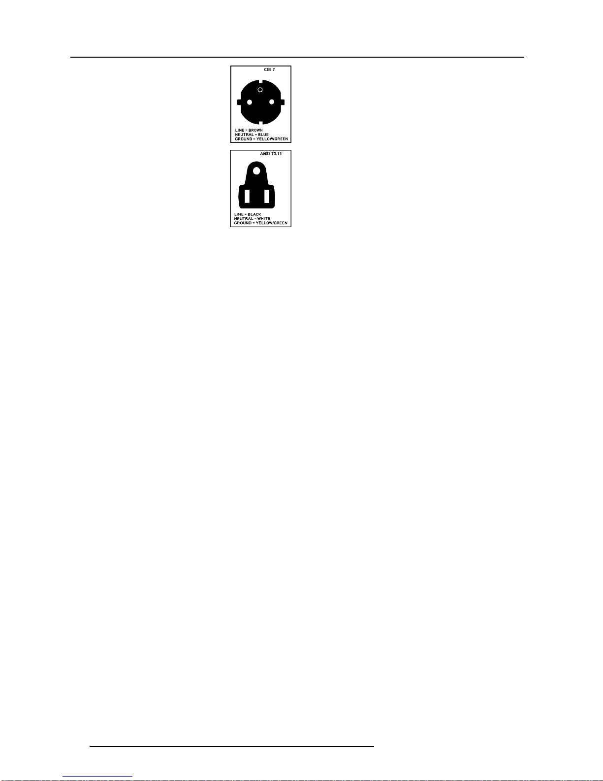
A. Mains lead (Power cord) with CEE 7 plug:
The wires of the mains lead are colored in
accordance with the following code.
Green and yellow: earth (safety earth)
Blue: neutral
Brown: line (live)
B. Power cord with ANSI 73.11 plug:
The wires of the power cord are colored in
accordance with the following code.
Green/yellow: ground
White: neutral
Black: line (live)
3. Do not allow anything to rest on the power cord. Do not locate this
product where persons will walk on the cord.
To disconnect the cord, pull it out by the plug. Never pull the cord
itself.
4. If an extension cord is used with this product, make sure that the
totaloftheampereratingsontheproductspluggedintotheextension
cord does not exceed the extension cord ampere rating. Also make
surethat thetotal ofall products pluggedinto thewall outlet does not
exceed 15 amperes.
5. Never push objects of any kind into this product through cabinet
slots as they may touch dangerous voltage points or short out parts
that could result in a risk of fire or electrical shock.
Neverspillliquidofanykindontheproduct. Should any liquid or solid
object fall into the cabinet, unplug the set and have it checked by
qualified service personnel before resuming operations.
6. Lightning - For added protection for this video product during a
lightning storm, or when it is left unattended and unused for long
periods of time, unplug it from the wall outlet. This will prevent
damage to the projector due to lightning and AC power-line surges.
On installation
1. Do not place this equipment on an unstable cart, stand, or table.
The product may fall, causing serious damage to it.
2. Do not use this equipment near water.
3. Slots and openings in the cabinet and the back or bottom are
provided for ventilation; to ensure reliable operation of the product
and to protect it from overheating, these openings must not be
blocked or covered. The openings should never be blocked by
placingthe productona bed,sofa, rug, or othersimilar surface. This
product should never be placed near or over a radiator or heat
register.
The projector should not be placed in a built-in installation or enclo-
sure unless proper ventilation is provided.
4.Do notblock the projectorcooling fansor free airmovement under
and around the projector. Loose papers or other objects may not be
nearer to the projector than 4" on any side.
On servicing
Do not attempt to service this product yourself, as opening or
removing covers may expose you to dangerous voltage potentials
and risk of electric shock!
Refer all servicing to qualified service personnel.
Unplug this product from the wall outlet and refer servicing to
qualified service personnel under the following conditions:
a. When the power cord or plug is damaged or frayed.
b. If liquid has been spilled into the equipment.
c.If the product has been exposed to rain or water.
d. If the product does not operate normally when the operating
instructions are followed.
Note : Adjust only those controls that are covered by the operating
instructions since improper adjustment of the other controls may
result in damage and will often require extensive work by a qualified
technician to restore the product to normal operation.
e.Iftheproduct hasbeendroppedorthecabinethasbeendamaged.
f. If the product exhibits a distinct change in performance, indicating
a need for service.
Replacement parts - When replacement parts are required, be sure
theservicetechnicianhasusedoriginalBARCOreplacementpartsor
authorizedreplacementpartswhichhavethesamecharacteristicsas
the BARCO original part. Unauthorized substitutions may result in
degraded performance and reliability, fire, electric shock or other
hazards. Unauthorized substitutions may void warranty.
Safety check - Upon completion of any service or repairs to this
projector, ask the service technician to perform safety checks to
determine that the product is in proper
operating condition.
On cleaning
Unplug this product from the wall outlet before cleaning. Do not
use liquid cleaners or aerosol cleaners. Use a damp cloth for
cleaning.
- To keep the cabinet looking brand-new, periodically clean it with a
soft cloth. Stubborn stains may be removed with a cloth lightly
dampenedwithmilddetergentsolution. Neverusestrongsolvents,
such as thinner or benzine, or abrasive cleaners, since these will
damage the cabinet.
- To ensure the highest optical performance and resolution, the
projection lenses are specially treated with an anti-reflective coat-
ing,therefore,avoidtouchingthelens. Toremove dust on the lens,
usea softdry cloth.Do not use a dampcloth, detergentsolution, or
thinner.
On repacking
Save the original shipping carton and packing material; they will
comeinhandyifyoueverhavetoshipyourequipment.Formaximum
protection, repack your set as it was originally packed at the factory.
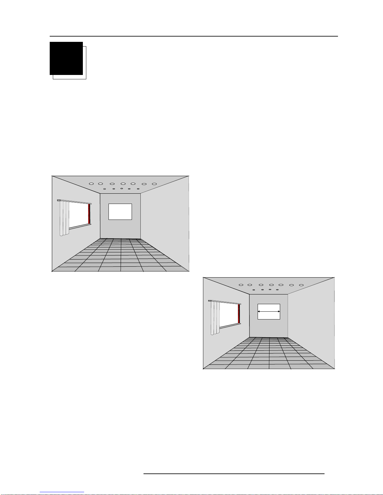
On illumination
Inordertoobtainthebestqualityfortheprojectedimage,itisessential
that the ambient light which is allowed to fall on the screen be kept to
an absolute minimum.
Wheninstallingtheprojectorandscreen,care mustbetakentoavoid
exposure to ambient light directly on the screen. Avoid adverse
illumination on the screen from direct sunlight or fluorescent lighting
fixtures.
The use of controlled ambient lighting, such as incandescent spot
light or a dimmer, is recommended for proper room illumination.
Where possible, care should also be taken to ensure that the floors
andwalls of theroomin whichtheprojector is tobeinstalled are non-
reflecting, dark surfaces. Brighter surfaces will tend to reflect and
diffuse the ambient light and hence reduce the contrast of the
projected image on the screen.

Unpacking and dimensions
2-1
5975857 BARCOGRAPHICS 1208s 220197
2UNPACKINGAND PROJECTOR DIMENSIONS
Unpacking
Contents of the shipping carton :
❒1 BARCOGRAPHICS 1208s projector
❒1 Remote Control Unit plus 1 battery 9V
❒1 power cord with outlet plug type CEE7 or ANSI 73.11
❒1 Owner's Manual of the projetor
❒1 Installation Manual of the projetor
To open the banding around the carton, pull out the clip as shown
below :
Take the projector out of its shipping carton and place it on a table.
Save the original shipping carton and packing material, which will
come in handy if you ever have to ship your projector. For maximum
protection, repack your projector as it was originally packed at the
factory.

Unpacking and dimensions
2-2 5975857 BARCOGRAPHICS 1208s 220197
Projector dimensions (in mm)
1101

Installation guidelines
3-1
5975857 BARCOGRAPHICS 1208s 220197
3INSTALLATION GUIDELINES
Installation guidelines
Carefulconsiderationofthingssuchasimagesize,ambientlight
level,projectorplacement and typeofscreentouseare critical
to optimize the use of the projection system.
Environment
Do not install the projection system in a site near heat sources such
as radiators or air ducts, or in a place subject to direct sunlight,
excessive dust or humidity. Be aware that room heat rises to the
ceiling; check that the temperature near the installation site is not
excessive.
What about ambient light ?
The ambient light level of any room is made up of direct or indirect
sunlightandthelightfixturesintheroom.Theamountofambientlight
will determine how bright the image will appear. So, avoid direct light
on the screen as much as possible.
Windows that face the screen should be covered by opaque drapery
while the set is being viewed. It is desirable to install the projecting
systeminaroomwhosewallsandfloorareofnon-reflectingmaterial.
The use of recessed ceiling lights and a method of dimming those
lightstoanacceptablelevelisalsoimportant.Toomuchambientlight
results in a ‘wash out’ of the projected image. This appears as less
contrast between the darkest and lightest parts of the image. With
biggerscreens,the‘washout’becomesmoreimportant.Asageneral
rule,darken the roomtothe point wherethereis just sufficientlightto
read or write comfortably. Spot lighting is desirable for illuminating
small areas so that interference with the screen is minimal. What image size? How big should the image
be?
The BARCOGRAPHICS 1208s is designed for projecting an image
widthfrom1.4m(4.6')to6m(20') withanaspectratioof4to3.Itleaves
the BARCO factory, adjusted as a ceiling/front projector for a screen
width of 2.4m. Changing the image size from the factory preset size
requires a realignment of the projector.
Which screen type?
There are two major categories of screens used for projection
equipment. Those used for front projected images and those for rear
projection applications.
Screens are rated by how much light they reflect (or transmit in case
of rear projection systems) given a determined amount of light
projectedtowardthem.The‘GAIN’ofascreenisthetermused. Front
and rear screens are both rated in terms of gain. The gain of screens
range from a white matte screen with a gain of 1 (x1) to a brushed
aluminizedscreenwithagainof 10 (x10) or more. Anotherimportant
considerationis the degreethescreen's gain varieswiththehorizon-
tal and vertical viewing angle. The choice between higher and lower
gain screens is largely a matter of personal preference.
In considering the type of screen to choose, determine where the
viewerswillbelocatedandgo for the highest gainscreenpossible. A
highgainscreenwillprovideabrighterpicturebutreducetheviewing
angle.
Formoreinformationaboutscreens, contact your local screen
supplier.
Screen width

Installation guidelines
3-2 5975857 BARCOGRAPHICS 1208s 220197
Where to install the projector ?
To indicate a correct installation position it is necessary to know :
❒thedistance from projectorto ceiling incase of ceilingmounted;or
the distance from projector to floor in case of Table mounted;
r
the distance from projector to screen.
To find this correct position for the BARCOGRAPHICS 1208s,
equipped with HD8 lenses, use the following formulas:
❒Install the projector water levelled in both directions
❒Install the projector perpendicular to the screen
PD[inch] = 1.269 x SW[inch] + 13.78
A[cm] = 0.12 x SW[inch] - 11.32
In metric :
In inch :
PD[m] = 1.269 x SW[m] + 0.3506
A[cm] = 12 x SW[m] - 28.75
Abbreviations used in the calculations and the drawings :
B = Distancebetweenceilingandtopofthescreen(ceilingmounted)
Distancebetweenfloorandbottomofthescreen(tablemounted)
A = Correction Value, extra value to be added to B to obtain the
correct installation position (In some cases the A value can be
negative)
CD = Totaldistancebetweenprojectorand ceiling (ceiling mounted)
Total distance between projector and floor (table mounted)
CD = A + B
Ceiling Mounted : when the result is negative, enlarge the
distance between ceiling and top of the screen, mount screen
lower, until CD becomes zero or positive.
Table Mounted : when the result is negative, enlarge the
distancebetweenfloorandbottomofthescreen,mountscreen
higher, until CD becomes zero or positive.
SW= Screen width
PD = Perpendicular distance between screen and projector
To obtain the right values, you can make use of the new option
included in the Installation Adjustment Mode to let the projector
calculatethe parametersautomatically. Please refer to Chapter8 for
details.
11.5 cm
green phosphor
Used phosphor width on the CRT faceplate (e.g. green CRT)
Mounting Configuration
Ceiling Mount
To install the BARCOGRAPHICS 1208s in the Ceiling configuration,
useBARCO'S CeilingMountKit(CM100)-OrderNumberR9827341.
Installation instructions are included with this kit.
Table Mount
BARCO offers a heavy-duty projection table with adjustable height
which allows the projector to be correctly positioned perfectly to the
installation requirements. Order Number - R9827740.
A
CD
PD
B
screen
projector
ceiling
screen width
SW
Front view
Top view

Installation set-up
4-1
5975857 BARCOGRAPHICS 1208s 220197
4INSTALLATION SET-UP
WARNING :
The projector's top cover is not supported with locking hinge. Open
with care and support the cover with your hand.
Access to Controls
Opening the top cover
Duringtheprojectorset-upandtheinstallationitisnecessarytoopen
the top cover. Follow the procedure as described below :
* turnbothlockscrewwithascrewdriveroracoincounterclockwise;
* lift up and pivot the top cover.
Removing the top cover
Duringsomeinstallationsitwillbeconvenienttoremovethetopcover
from the projector totally.
Proceed as follows :
➊loosen the screw locks by turning a quarter counter clockwise.
➋pull out the hing-joints.
➌➌ left up the top cover.
Lock screws

Installation set-up
4-2 5975857 BARCOGRAPHICS 1208s 220197
Scan Adaptation
The scan switches must be placed in the correct position which corresponds to the desired scanning configuration.
To change the scanning, it is necessary to remove the projector top cover and to open the protection plate.
For opening the projector's top cover, see 'Access to controls'.
Getting access to the scan switches
➊open the top cover and remove it from the projector (see p.4-1);
➋loosen the 3 lock screws with a screwdriver by turning a quarter
counterclockwise;
➌remove the fixation screw nearby the fan.
WARNING !
TURN OFF PROJECTOR AND UNPLUG THE POWER
CORD BEFORE CHANGING THE SCAN DIRECTION.
Lock screws
Fixation screw
➍➍ lift up the metal cover plate and pivot it to the lens side.
➎take off the cover plate.
➏loosenthelockscrewofthescanswitchesmoduleplate.
➐pivot the scan switches module plate to the lenses.

Installation set-up
4-3
5975857 BARCOGRAPHICS 1208s 220197
Horizontal Scan Switches
Three switches are used, one for each CRT. When changing
thehorizontalscan,insurethatallthreeswitchesaresetinthe
same position. See positions of the switches for the corre-
sponding projector configuration.
Vertical Scan Switch
One switch for the three CRT's is used. See position of the
switch for the corresponding projector configuration.
After setting the scan switches, close all the metal protection plates
and secure them with the retaining screws.
Close the top cover and reconnect the power cord to the wall outlet.
Note :
SwitchingoverfromFloortoCeilingorviceversarequiresacomplete
readjustment of picture geometry and convergence.
Tocheckthecurrentpositionofthescanswitches,proceedasfollows:
Attention: thischeckprocedurecanonlybedoneafterpower(mains)
connection. So, first continue with the projector set-up and the
connections and then return to this checking procedure.
Switch on the BARCOGRAPHICS1208s and press ADJUST to start
up the adjustment mode. Select 'SERVICE' by pushing the control
stick forward or backward and press ENTER. The service menu will
be displayed. Select 'IDENTIFICATION' and press ENTER. The
screen gives information about the projectors configuration. All
projectors leave the factory set for a ceiling/front configuration.
Follow next procedure to check the configuration :
➊switch on the projector;
➋the projector starts up on the last selected source;
➌press ADJUST;
➍highlight 'SERVICE' by pushing the control stick forward or back-
ward and press ENTER : the 'SERVICE MODE MENU' will be
displayed;
➎highlight'IDENTIFICATION'bypushingthecontrolstickforwardor
backward and press ENTER.
The projector will display the 'IDENTIFICATION SCREEN'.
Thisscreengivesthecurrentinformationabouttheprojectorconfigu-
ration in the line entitled 'config'.
B
G
R
Horizontal
deflection switches Vertical
deflection switch
Projector configurations (Switch settings)
Front-ceiling
R
G
B
Front-table
Rear-ceiling
Rear-table
R
G
B R
G
B
R
GB
pressed
pressed
pressed pressed
not pressed
not pressed
not pressed
not pressed
Proj.address: 001
Soft.Version :6.00
Config.: Ceiling
Front
BaudratePC:9600
Text : ON
SerialNo.:103589552
GRAPHICS 1208S
SERVICE MODE
IDENTIFICATION
COPY A BLOCK
DELETE A BLOCK
DELETE ALL BLOCKS
CHANGE PASSWORD
CHANGE LANGUAGE
RUN TIME
DYNAMIC ASTIGMATISM
MORE...
Select with
é
or
ê
then <ENTER>;
<EXIT> to return.
ADJUSTMENT MODE
Select a path from
below:
Select with or
then <ENTER>
<EXIT> to return
source 1
GUIDED
RANDOM ACCESS
INSTALLATION
SERVICE
IRIS

Projector set-up
5-1
5975857 BARCOGRAPHICS 1208s 220197
5PROJECTOR SET-UP
TheDIPswitchesonthecontrollerunitallowtheSET-
UP of the projector :
❒8 DIP switches for setting the projector address
r
1 DIP switch for setting the power up mode
r
3DIPswitchesforsetting the baud rateforcommu-
nication
r
1 DIP switch for setting the password mode
To gain access to the DIP switches :
* open the top cover,
* loosen the 3 retaining screws on both sides of the
metal protection plate,
* loosen the 3 screws on the rear side of the metal
frame, lift up the metal cover plate and pivot to the
lens side (please refer to Chapter 4 'Installation set-
up').
The DIP switches are located on the back side of this
metal protection plate.
StdBY
MAIN POWER
PROCESSOR CYCLES
BLOCK MATCH
ERROR
RCU
RCVDS
PC
PAUSE
PROJECTOR ADDRESS
(sum)
OFF ON
BAUD RATE TABLE
TO COMPUTER
POWER UP MODE
OPERATING MODE WHEN
POWER IS SWITCHED ON
ON
OFF PLAYING
StdBY
PASSWORD MODE
ON
OFF YES
NO
RESERVED
POWER UP MODE
PASSWORD MODE
BAUD RATE CODE
(sum)
P
ASSWORD REQUIRED
FOR ADJUSTMENT
CODE
0
1
2
3
4
5
6
7
SPEED
110
150
300
600
1200
2400
4800
9600
01
128
64
32
16
8
4
2
1
1
2
3
4
5
6
7
8
1
2
3
4
2
1
1
2
3
4
5
6
7
8
I
2
C SHORTED

Projector set-up
5-2 5975857 BARCOGRAPHICS 1208s 220197
Setting the projector address
The projector's address may be set to any value between 0 and 255.
When the address is set, the projector can be controlled now by :
❒RCU for addresses between 0 and 9;
❒IBMPC(orcompatible)orAppleMACforaddressesbetween0and
255.
0
9
Addressable with RCU
A
ddressable with PC, MAC
o
r workstation
255
1 128
2 64
3 32
4 16
5 8
6 4
7 2
8 1
Setting the address is a hardware SET-UP of your projector which
mustbedone during installation.Usethe8DIP switches providedon
the controller unit.
Each DIP switch has its own decimal value. The sum of the values
associatedto those DIPswitchesgives the address.Asshown in the
table,ifSwitchNo.1issettoON,itrepresentsadecimalvalueof128,
Switch No.2 for 64, Switch No.3 for 32, and so forth.
In the given example, the projector address is set to 202 :
DIP switch No. : 1 2 3 4 5 6 7 8
Position ON/OFF : 1 1 0 0 1 0 1 0
Sum : 1x128 + 1x64 + 0x32 + 0x16 + 1x8 + 0x4 + 1x2 + 0x1 = 202
Note :
when the address button on the RCU is pressed, the projector will
display its own address on the screen. Once the address button is
pressed, to continue using your RCU, it is necessary to enter an
address, even when the displayed address is correct. Use the
numeric keys to enter the address.
1
2
3
4
5
6
7
8
0
1
OFF ON
Switch No Value
PROJECTOR
ADDRESS
001

Projector set-up
5-3
5975857 BARCOGRAPHICS 1208s 220197
1
2
3
4
5
6
7
8
O
N
OFF
Power-up mode
OFF ON
Power-up mode
The projector can start up in two different modes. The start up mode
is determined by the position of DIP Switch No. 4 of another set of 8
DIPswitchesonthecontrollerunit(one set of 8 switchesareusedfor
projector address setting).
Position of the DIP Switch No. 4 (power up mode) :
ON : operational mode
OFF: stand-by mode
Source 2
Fh= 15.6 kHz
Fv= 50 Hz
❒❒ Operational mode
When the power switch on the rear of the projector is pressed, the
projector displays the last selected source if available, otherwise it
remains on that source number until the source becomes available.
The on screen indication is only available when the "Text" function is
set to "ON".
❒❒ Stand-By mode
When the power switch on the rear of the projector is pressed, the
projectorstartsupinthestand-bymode.Thestand-bykeyontheRCU
is used to turn the projector ON and OFF.
Position of DIP switches and baud rate codes :
Baud Rate for communication with a
computer
The communication speed between the projector and the computer
has8 possiblesettings. With DIP SwitchNo. 6,No.7 and No.8of the
8 DIP switches on the controller unit, labelled as ‘Baud rate code
(sum)’, it is possible to select the baud rate (communication speed).
Each DIP switch has its own decimal value. The sum of the values
associated to those DIP switches gives the baud rate code. Each
baud rate code corresponds an communication speed.
baud rate code speed
0 110
1 150
2 300
3 600
4 1200
5 2400
6 4800
7 9600
More information about computer communication with the BARCO-
GRAPHICS 1208s is available in the Projector Control Software
manual.
1
2
3
4
5
6
7
8
O
FF
ON
01
Baud rate
DIP switches
4
2
1

Projector set-up
5-4 5975857 BARCOGRAPHICS 1208s 220197
Password mode
With DIP Switch No.5 of the second set of 8 DIP switches on the
controller unit, the projector adjustments can be protected with a
password. When the password feature is enabled, the user has to
enterapasswordbefore he can entertheadjustmentmode(formore
information about password setting and reprogramming the pass-
word, see Installation adjustment).
When the password menus are disabled (adjust mode is unpro-
tected),the adjust modecanbe selected bypressingthe <ADJUST>
key. This position of the DIP switch is useful for qualified service
techniciansbecausethey do notneedapassword to entertheadjust
mode.
Position of DIP Switch No.5 :
ON : password mode enabled
OFF : password mode disabled
Password
mode
1
2
3
4
5
6
7
8
O
FF
ON
01

AC power connection
6-1
5975857 BARCOGRAPHICS 1208s 220197
6AC POWER CONNECTION
AC Power (mains) cord connection
Use the supplied cord to connect your projector to the
wall outlet. Plug the female power connector into the
male connector at the back of the projector.
This projector may be connected to an IT-power sys-
tem.
Preparing your power cord
Mains lead (power cord) with CEE7 plug
Asthecoloursofthewiresinthemainsleadofthisapparatusmaynot
correspond with the coloured markings identifying the terminals in
your plug, proceed as follows:
❒The yellow/green wire is ground and must be connected to the
terminal in the plug which is marked by the letter E or by the safety
earth symbol or coloured yellow and green.
❒The blue wire is neutral and must be connected to the terminal
marked with the letter N or coloured black.
❒The brown wire is the line and must be connected to the terminal
marked with the letter L or coloured red.
The wires of the delivered mains lead (power cord) are coloured in
accordance with the following code :
Yellow and Green : ground
Blue : neutral
Brown : live
Power cord with an ANSI 73.11 plug
The wires of the delivered mains lead (power cord) are coloured in
accordance with the following code :
Yellow and Green : ground (earth)
White : neutral
Black : live
RS232 OUT
RS232 IN
IR REMOTE
REMOTE IR
RS232 OUT
RS232 IN
V NOM
I MAX
FREQ
120/230 Volt
7/5Amp
50/60Hz
685

AC power connection
6-2 5975857 BARCOGRAPHICS 1208s 220197
AC Power check
Check the power voltage which is determined by the ART. NR.
(Article number) included in the label pasted on the backside of the
projector.
Projectors with the ART. NR. R9000901 must be connected to a 230
VAC power source.
Projectors with the ART. NR. R9000908 must be connected to a 120
VAC power source.
If the indicated voltage is different from that of the wall outlet, call a
qualified technician for power adaptation of the projector.
AC Input power (mains) voltage adaptation
Attention !
The BARCOGRAPHICS 1208s - R9000893 leaves the factory to
operate on a mains (power) input of 230 Vac.
The BARCOGRAPHICS 1208s - R9000896 leaves the factory to
operate on a mains (power) input of 120 Vac.
Adaptation of the power input of the projector between 230 Vac
and 120Vac or vice versa is possible.
Follow the procedure as described below to adapt the voltage :
➊WARNING: turn off the projector and be sure the AC Power
Cord is unplugged before starting the procedure !
➋Open the top cover (see 'Access to controls' on p.4-1).
➌Unscrew the retaining screws of the power input protection
plate.
➍Remove the power input protection by sliding it a little back-
wards and lifting it up.
➎ Pull out the 'power selector plug' and re-insert it as illustrated in
the drawing, depending on the wall outlet in the room.
➎Pull out the fuses and place the correct fuses in their sockets.
See the table on next page for the correct type of fuses.
➏Re-installthe protectionplate. Insert the theplate untilthe pins
fitintothegroovesofthebottomplate. Therightsideoftheplate
must be pushed behind the metal frame. The notch fits around
the bolt. Secure the correct position by turning in the 3 screws.
Retaining screws
230V
120V
230V operation
120V operation
2xT5A/250V 2xT10A/250V
This manual suits for next models
1
Table of contents
Other Barco Projector manuals

Barco
Barco R9002030 User manual

Barco
Barco R9040171 User manual

Barco
Barco DP2K8S User manual

Barco
Barco Galaxy NH-12 User manual

Barco
Barco R9002400 User manual

Barco
Barco HDQ--2K40 User guide

Barco
Barco RLM-W12 User manual

Barco
Barco R9002380 User manual

Barco
Barco DP-1500 User manual

Barco
Barco F22 Series User manual

Barco
Barco iCon H600 User manual

Barco
Barco REALITY 8200 TCR+ User manual

Barco
Barco DP2K--32B User manual

Barco
Barco BARCOSLM R6 User manual

Barco
Barco fD70-DL User manual

Barco
Barco BARCOREALITY 8200TCR+ User manual

Barco
Barco R5975039 User manual

Barco
Barco F70-series User manual

Barco
Barco OV-708 User manual

Barco
Barco RLM-W12 User manual