Barco R9040171 User manual

SIMULATION PRODUCTS
BARCOREALITY SIM6ULTRAMM
R9040171
OWNER’SMANUAL
22102002 R5976495/01

Barco nv Simulation Products
600 Bellbrook Ave, Xenia OH 45385
Phone: +1 (937) 372 7579
Fax: +1 (937) 372 8645
E-mail: [email protected]
Visit us at the web: www.eis.barco.com
Barco nv Simulation Products
Noordlaan 5, B-8520 Kuurne
Phone: +32 56.36.82.11
Fax: +32 56.36.84.86
E-mail: info@barco.com
Visit us at the web: www.barco.com
Printed in Belgium

Copyright ©
All rights reserved. No part of this document may be copied, reproduced or translated. It shall not otherwise be recorded, transmitted or
stored in a retrieval system without the prior written consent of BARCO.
Changes
Barco provides this manual “as is” without warranty of any kind, either expressed or implied, including but not limited to the implied war-
ranties or merchantability and fitness for a particular purpose. Barco may make improvements and/or changes to the product(s) and/or the
program(s) described in this publication at any time without notice.
This publication could contain technical inaccuracies or typographical errors. Changes are periodically made to the information in this
publication; these changes are incorporated in new editions of this publication.
Federal Communication Commission (FCC Statement)
This equipment has been tested and found to comply with the limits for a class A digital device, pursuant to Part 15 of the FCC rules.
These limits are designed to provide reasonable protection against harmful interference when the equipment is operated in a commercial
environment. This equipment generates, uses, and can radiate radio frequency energy and, if not installed and used in accordance with
the instruction manual, may cause harmful interference to radio communications. Operation of this equipment in a residential area may
cause harmful interference, in which case the user will be responsible for correcting any interference.
Trademarks
Brand and product names mentioned in this manual may be trademarks, registered trademarks or copyrights of their respective holders.
All brand and product names mentioned in this manual serve as comments or examples and are not to be understood as advertising for
the products or their manufactures.


Table of contents
TABLE OF CONTENTS
1. Packaging andDimensions .......................................................................................3
1.1 Boxcontent.............................................................................................................................. 3
1.2 ProjectorPackaging .................................................................................................................... 3
1.3 Lens Packaging ......................................................................................................................... 4
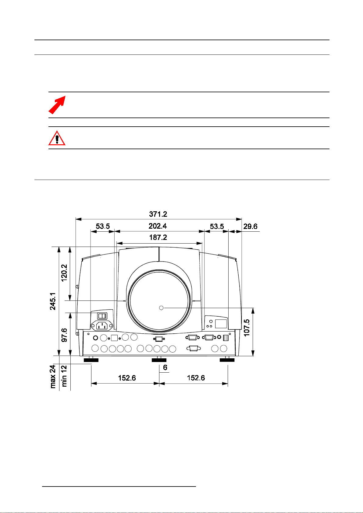
1.4 Dimensions.............................................................................................................................. 4
2. InstallationGuidelines.............................................................................................. 7
2.1 Installationguidelines................................................................................................................... 7
2.2 Configuration............................................................................................................................ 8
2.3 Lenses................................................................................................................................... 9
2.3.1 Lenses ............................................................................................................................ 9
2.3.2 Lens formulas ...................................................................................................................10
2.3.3 Lens installation .................................................................................................................11
2.3.4 Cleaning the lens................................................................................................................11
2.4 Batteries................................................................................................................................12
2.4.1 Batteryinstallation...............................................................................................................12
2.4.2 Batteryreplacement.............................................................................................................12
3. Connections.........................................................................................................15
3.1 Power connection......................................................................................................................15
3.2 Input Source connection...............................................................................................................15
3.2.1 Inputfacilities....................................................................................................................15
3.2.2 5-cable input (BNC1)............................................................................................................15
3.2.3 5-cable data input (BNC2) ......................................................................................................16
3.2.4 Video input.......................................................................................................................16
3.2.5 S-Video input ....................................................................................................................17
3.2.6 DigitalVisualInterface(DVI)input..............................................................................................18
3.2.7 SDIinput.........................................................................................................................18
3.2.8 HDSDI input .....................................................................................................................19
3.2.9 Communications.................................................................................................................19
3.2.9.1 RS232 IN connection .....................................................................................................19
4. Gettingstarted......................................................................................................21
4.1 RCU&Localkeypad...................................................................................................................21
4.2 Terminologyoverview..................................................................................................................21
4.3 Switchingon............................................................................................................................23
4.4 Lampruntime...........................................................................................................................24
4.5 Quicksetupadjustments..............................................................................................................25
4.5.1 QuicklensAdjustment ..........................................................................................................25
4.5.2 UsingtheRCU...................................................................................................................25
4.5.3 Projector address................................................................................................................26
4.5.3.1 Addresssetting ...........................................................................................................27
4.5.3.2 Displaying and Programming addresses into the RCU..................................................................27
4.5.4 Controllingtheprojector.........................................................................................................27
4.5.5 Usingthemenu..................................................................................................................28
4.5.6 Using the Dialogboxes ..........................................................................................................29
5. SourceSelection...................................................................................................31
5.1 Source selection .......................................................................................................................31
5.2 CompositeVideo ......................................................................................................................32
5.3 S-Videoselection ......................................................................................................................32
6. GeneralMenu.......................................................................................................35
6.1 Pause...................................................................................................................................35
6.2 Freeze..................................................................................................................................35
6.3 Standby Timer..........................................................................................................................36
6.4 Identification............................................................................................................................37
6.5 Runtimes...............................................................................................................................37
6.6 History..................................................................................................................................38
6.7 Resetruntime ..........................................................................................................................39
6.8 Runtimewarning.......................................................................................................................40
6.9 LampDimming.........................................................................................................................41
7. ImageMenu .........................................................................................................43
7.1 Settings.................................................................................................................................43
7.1.1 Contrast..........................................................................................................................44
7.1.2 Brightness.......................................................................................................................44
7.1.3 Color.............................................................................................................................44
7.1.4 Tint(hue).........................................................................................................................44
7.1.5 Sharpness .......................................................................................................................45
7.1.6 Gamma..........................................................................................................................45
7.1.7 Phase............................................................................................................................45
7.2 Aspectratio.............................................................................................................................45
R5976495 BARCOREALITY SIM 6 ULTRA MM 22102002 1

Table of contents
7.3 Shownativeresolution.................................................................................................................46
7.4 Blanking................................................................................................................................47
7.5 Keystone ...............................................................................................................................48
7.6 Colortemperature......................................................................................................................49
7.7 Filmmodedetection....................................................................................................................50
7.8 Advancedsettings .....................................................................................................................51
7.8.1 Noise reduction .................................................................................................................51
7.8.2 Dynamic color depth ............................................................................................................51
7.9 Input balance...........................................................................................................................51
7.10AGConVideo .........................................................................................................................51
7.11Manual Gain Control...................................................................................................................52
8. Tools Menu..........................................................................................................53
8.1 IntroductiontoPiP .....................................................................................................................53
8.2 PiPselect...............................................................................................................................55
8.3 PiP add window ........................................................................................................................55
8.4 PiP remove window....................................................................................................................56
8.5 PiPlayout...............................................................................................................................57
8.5.1 PiPSave.........................................................................................................................57
8.5.2 PiPrenamelayout...............................................................................................................57
8.5.3 PiPdeletelayout ................................................................................................................58
8.6 PiPAdjust..............................................................................................................................59
8.7 Diagnostics.............................................................................................................................60
9. SignalMenu.........................................................................................................61
9.1 Switchingmode........................................................................................................................61
9.2 Background ............................................................................................................................61
10.Imagefilesmenu...................................................................................................63
10.1Load file................................................................................................................................63
10.2Editfile.................................................................................................................................64
10.3Renamefile............................................................................................................................66
10.4Copy ...................................................................................................................................67
10.5Delete..................................................................................................................................68
11.Installationmenu...................................................................................................69
11.1Lens adjustments......................................................................................................................69
11.2Projectoraddress......................................................................................................................70
11.3Orientation.............................................................................................................................71
11.4Fullscreenrepresentation.............................................................................................................72
11.5Language ..............................................................................................................................72
11.6Quickaccesskeys.....................................................................................................................73
11.7RS232 baudrate .......................................................................................................................73
11.8Centeredmenu........................................................................................................................74
11.9Startupscreen.........................................................................................................................74
11.10Take screenshot......................................................................................................................75
11.11Sliderboxposition ....................................................................................................................76
11.12AutoImageSetup.....................................................................................................................77
11.13Changepassword....................................................................................................................78
11.14Autofileload..........................................................................................................................79
A.StandardImage Files...............................................................................................81
A.1Tableoverview .........................................................................................................................81
B.CleaningtheDustfilter.............................................................................................85
B.1 Cleaning................................................................................................................................85
Glossary.................................................................................................................87
Index......................................................................................................................89
2R5976495 BARCOREALITY SIM 6 ULTRA MM 22102002

1. Packaging and Dimensions
1. PACKAGING AND DIMENSIONS
This chapter handles about the way the projector is packed and gives an overview of the dimensions.
• Box content
• Projector Packaging
• Lens Packaging
• Dimensions
1.1 Box content
CEE7
European power plug to connect the power cord to the wall outlet.
ANSI 73.11
American power plug to connect the power cord to the wall outlet.
Content
• 1 projector BARCOREALITY SIM6 ULTRA MM(weight ± 17 kg or 37.4 lbs)
• 1 remote control unit RCU + 2 batteries.
• 2 power cables with outlet plug type CEE7 and ANSI 73.11.
• 1 owners manual
• 1 safety manual
1.2 Projector Packaging
Way of Packaging
The projector is packed in a carton box. To provide protection during transportation, the projector is surrounded with foam. The
package is secured with banding and fastening clips.
To unpack
1. Release the fastening clips.
2. Remove the banding. Handle as shown in the drawing. (image 1-1)
3. Take the projector out of its shipping carton and place it on a table.
Image 1-1
Save the original shipping carton and packing material, they will be necessary if you ever have to ship your
projector. For maximum protection, repack your projector as it was originally packed at the factory.
Never transport the projector with the lens mounted on it !
Alwaysremovethelensbeforetransportingtheprojec
tor.
R5976495 BARCOREALITY SIM 6 ULTRA MM 22102002 3

1. Packaging and Dimensions
1.3 Lens Packaging
Way of Packaging
Lenses are supplied as an individual item.
They are packed in a carton box.
Save the original shipping carton and packing material, they will be necessary if you ever have to transport
the lens.
Never transport the projector with the lens mounted on it !
Always remove the lens before transporting the projector.
1.4 Dimensions
Dimensions overview
Dimensions are given in mm (1 inch = 25.4 mm)
Image 1-2
4R5976495 BARCOREALITY SIM 6 ULTRA MM 22102002

1. Packaging and Dimensions
Image 1-3
Image 1-4
R5976495 BARCOREALITY SIM 6 ULTRA MM 22102002 5

1. Packaging and Dimensions
6R5976495 BARCOREALITY SIM 6 ULTRA MM 22102002

2. Installation Guidelines
2. INSTALLATION GUIDELINES
Overview
• Installation guidelines
• Configuration
• Lenses
• Batteries
Before installing the projector, read first the safety instructions supplied with the BARCOREALITY SIM6 UL-
TRA MM.
2.1 Installation guidelines
Ambient Temperature Conditions
Careful consideration of things such as image size, ambient light level, projector placement and type of screen to use are critical to
the optimum use of the projection system.
Max. ambient temperature : 40 C or 104 F
Min. ambient temperature : 0 Cor32 F
The projector will not operate if ambient air temperature falls outside this range (0 C- 40 Cor32F-104 F).
Storage temperature: -35 Cto+65C (-25.6 F to 149 F)
Humidity Conditions
Storage: 0 to 98 % RH Non-condensing
Operation: 0 to 95 % RH Non-condensing
Environment
Do not install the projection system in a site near heat sources such as radiators or air ducts, or in a place subject to direct sunlight,
excessive dust or humidity. Be aware that room heat rises to the ceiling; check that temperature near the installation site is not
excessive.
Harmful Environmental Contamination Precaution
Environment condition check
A projector must always be mounted in a manner which ensures the free flow of clean air into the projectors ventilation inlets. For
installations in environments where the projector is subject to airborne contaminants such as that produced by smoke machines or
similar (these deposit a thin layer of greasy residue upon the projectors internal optics and imaging electronic surfaces, degrading
performance), then it is highly advisable and desirable to have this contamination removed prior to it reaching the projectors clean
air supply. Devices or structures to extract or shield contaminated air well away from the projector are a prerequisite, if this is not a
feasible solution then measures to relocate the projector to a clean air environment should be considered.
Only ever use the manufactures recommended cleaning kit which has been specifically designed for cleaning optical parts, never
use industrial strength cleaners on a projectors optics as these will degrade optical coatings and damage sensitive optoelectronic
components. Failure to take suitable precautions to protect the projector from the effects of persistent and prolonged air contami-
nants will culminate in extensive and irreversible ingrained optical damage. At this stage cleaning of the internal optical units will be
non-effective and impracticable. Damage of this nature is under no circumstances covered under the manufactures warranty and
may deem the warranty null and void. In such a case the client shall be held solely responsible for all costs incurred during any
repair. It is the clients responsibility to ensure at all times that the projector is protected from the harmful effects of hostile airborne
particles in the environment of the projector. The manufacture reserves the right to refuse repair if a projector has been subject to
wantful neglect, abandon or improper use.
What about ambient light ?
The ambient light level of any room is made up of direct or indirect sunlight and the light fixtures in the room. The amount of ambient
light will determine how bright the image will appear. So, avoid direct light on the screen. Windows that face the screen should be
covered by opaque drapery while the set is being viewed. It is desirable to install the projection system in a room whose walls and
floor are of non-reflecting material. The use of recessed ceiling lights and a method of dimming those lights to an acceptable level
is also important. Too much ambient light will ‘wash out’ of the projected image. This appears as less contrast between the darkest
R5976495 BARCOREALITY SIM 6 ULTRA MM 22102002 7

2. Installation Guidelines
and lightest parts of the image. With bigger screens, the ‘wash out’ becomes more important. As a general rule, darken the room to
the point where there is just sufficient light to read or write comfortably. Spot lighting is desirable for illuminating small areas so that
interference with the screen is minimal.
Which screen type ?
There are two major categories of screens used for projection equipment. Those used for front projected images and those for rear
projection applications.
Screens are rated by how much light they reflect (or transmit in the case of rear projection systems) given a determined amount
of light projected toward them. The ‘GAIN’ of a screen is the term used. Front and rear screens are both rated in terms of gain.
The gain of screens range from a white matte screen with a gain of 1 (x1) to a brushed aluminized screen with a gain of 10 (x10)
or more. The choice between higher and lower gain screens is largely a matter of personal preference and another consideration
called the Viewing angle. In considering the type of screen to choose, determine where the viewers will be located and go for the
highest gain screen possible. A high gain screen will provide a brighter picture but reduce the viewing angle. For more information
about screens, contact your local screen supplier. A high gain screen will provide a brighter picture but reduce the viewing angle.
Whatimagesize?Howbigshouldtheimagebe?
The projector is designed for projecting an image size (video) from 1.00m (3.3ft) to 6.00m (19.7ft) with a aspect ratio of 5 to 4.
2.2 Configuration
Which configuration can be used ?
The projector can be installed to project images in four different configurations :
• Front/table
• Rear/table
• Front/ceiling
• Rear/ceiling
Positioning the projector
Drawings are given for a nominal lens position.
8R5976495 BARCOREALITY SIM 6 ULTRA MM 22102002

2. Installation Guidelines
Image 2-1
B Distance between ceiling and top of the screen or between floor and bottom of the screen.
A Correction value, distance between bottom side of projector (without feet) and middle of the lens. Value to be subtracted from
B to obtain the correct installation position. (A value is a constant value for all screen widths and type of lenses, A = 124.1 mm
or 4.89 inch)
CD Total distance between projector and ceiling or projector and floor.
SWScreen width
SH Screen height (image height)
PD Projector distance, distance between screen and projector
2.3 Lenses
Overview
• Lenses
• Lens formulas
• Lens installation
• Cleaning the lens
2.3.1 Lenses
Available lenses
The following lenses are available, or will become available (contact a BARCO service center) as an option :
Lenses Standard version Sheimpflug version
QFD(1.27:1) R9840400 R9840600
QFD(2.5:1) R9840290 R9840470
R5976495 BARCOREALITY SIM 6 ULTRA MM 22102002 9

2. Installation Guidelines
Lenses Standard version Sheimpflug version
QFD(1.4-2.1:1) R9840380 R9840610
QFD(2.1-3.0:1) R9840390 R9840590
QFD(3.4-4.5:1) R9840060 R9840580
QFD(4.5-6.0:1) R9840100 R9840460
QFD(7:1) R9840410 —
QGD(0.8:1) / SW: (1-1.4)m R9829800 R9840480
QGD(0.8:1) / SW: (1.7-2.4)m R9840040 R9840490
QGD(0.86:1) R9840491 R9840492
2.3.2 Lens formulas
Formulas
Lenses Metric Formulas (meter) Inch Formulas (inch)
QFD(1.27:1) PD = 1.29 x SW — 0,0195 + 0,00276 /
SW PD = 1.29 x SW — 0.768 + 4.278 / SW
QFD(2.5:1) PD = 2.427 x SW + 0,025 + 0,022 / SW PD = 2.427 x SW +0.984 + 34.10 / SW
QFD(1.4-2.1:1) PDmin = 1,44 x SW + 0,0287 — 0,022 /
SW
PDmax = 2,20 x SW — 0,01 + 0,020 / SW
PDmin =1.44xSW+1.13—34.10/SW
PDmax = 2.20 x SW — 0.39 + 31.00 / SW
QFD(2.1-3.0:1) PDmin = 2,13 x SW — 0,10 + 0,056 / SW
PDmax = 2,90 x SW + 0,10 — 0,0745 /
SW
PDmin = 2.13 x SW — 3.937 + 86.80 /
SW
PDmax = 2.90 x SW + 3.937 — 115.48 /
SW
QFD(3.4-4.5:1) PDmin = 3,374 x SW — 0,115 + 0,0575 /
SW
PDmax = 4,433 x SW — 0,133 + 0,0556
/SW
PDmin = 3.374 x SW — 4.53 + 89.13 /
SW
PDmax = 4.433 x SW — 5.24 + 86.18 /
SW
QFD(4.5-6.0:1) PDmin = 4,29 x SW — 0,02 + 0,0009 /
SW
PDmax = 5,86 x SW + 0,15 + 0,0121 /
SW
PDmin = 4.29 x SW — 0.787 + 1.395 /
SW
PDmax = 5.86 x SW + 5.906 + 18.755 /
SW
QFD(7.0:1) PD = 6,882 x SW — 0,045 + 0,048 / SW PD = 6.882 x SW — 1.772 + 74.4 / SW
QGD(0.8:1) / SW: (1-1.4)m PD = 0,775 x SW — 0,048 + 0,0074 /
SW PD = 0.775 x SW — 1.89 + 11.47 / SW
QGD(0.8:1) / SW: (1.7-2.4)m PD = 0,775 x SW — 0,048 + 0,0072 /
SW PD = 0.775 x SW — 1.89 + 11.47 / SW
QGD(0.86:1) PD = 0,8376 x SW + 0,00254 — 0,0150
/SW PD = 0.8376 x SW + 0.1 — 23.25 / SW
Lens program to calculate the projector distance is available on the BARCO web site :
http://www.barco.com/projection_systems/customer_services/lens_program.asp
10 R5976495 BARCOREALITY SIM 6 ULTRA MM 22102002

2. Installation Guidelines
2.3.3 Lens installation
How to install ?
Follow the next procedure :
1. Open the lens cover of the projector by pivoting it up and take it off. (image 2-2)
2. Pull the lens locks levers backwards to open the lens locks. (image 2-3)
3. Put the lens on the lens holder. (image 2-4)
4. Push the lens locks back in position and lock the levers.
5. Plug the wires of the motor unit into the connector (image 2-5)
6. Re-install the lens cover.
Image 2-2
Image 2-3
Image 2-4 Image 2-5
The procedure for the mounting of a Scheimpflug lens is different.
Refer to the installation manual of the lens.
Never transport the projector with the lens mounted on it !
Always remove the lens before transporting the projector.
2.3.4 Cleaning the lens
To minimize the possibility of damaging the optical coating or scratching exposed lens surface, we have de-
veloped recommendations for cleaning the lens. FIRST, we recommend you try to remove any material from
the lens by blowing it off with clean, dry deionized air. DO NOT use any liquid to clean the lenses.
R5976495 BARCOREALITY SIM 6 ULTRA MM 22102002 11

2. Installation Guidelines
Necessary tools
TorayseeTM cloth (delivered together with the lens kit). Order number : R379058.
Howtocleanthelens?
Proceed as follow :
1. Always wipe lenses with a CLEAN TorayseeTM cloth.
2. Always wipe lenses in a single direction.
Warning: Do not wipe back and forwards across the lens surface as this tends to grind dirt into the coating.
3. Do not leave cleaning cloth in either an open room or lab coat pocket, as doing so can contaminate the cloth.
4. If smears occur when cleaning lenses, replace the cloth. Smears are the first indication of a dirty cloth.
Do not use fabric softener when washing the cleaning cloth or softener sheets when drying the cloth.
Do not use liquid cleaners on the cloth as doing so will contaminate the cloth.
Other lenses can also be cleaned safely with this TorayseeTM cloth.
2.4 Batteries
Overview
• Battery installation
• Battery replacement
2.4.1 Battery installation
How to install the battery
Two batteries are packed together with the RCU. Before using your RCU, install first these batteries.
1. Remove the battery cover on the backside by pushing the handle a little towards the bottom of the RCU.
2. Lift up the top side of the cover at the same time.
3. Insert the batteries as indicated in the RCU.
4. Put the battery cover on its place.
2.4.2 Battery replacement
How to replace the batteries in the RCU
To replace the batteries :
1. Remove the battery cover on the backside by pushing the handle a little towards the bottom of the RCU.
2. Lift up the top side of the cover at the same time.
3. Push on the + side of the battery towards the - side
4. Lift up the battery at the same time.
5. Repeat for the second battery.
6. Insert the batteries as indicated in the RCU (battery type AA or LR6 or equivalent).
7. Put the battery cover on its place. (image 2-6)
12 R5976495 BARCOREALITY SIM 6 ULTRA MM 22102002

2. Installation Guidelines
Image 2-6
Note, only important if more than one projector is installed in the room.
The common address can be zero (0) or one (1). The standard RCU are setup for common address zero. To
change the common address of the RCU, contact a BARCO service center. If it is necessary to program the
projector address into the RCU, see chapter ’Getting Started’.
Projector address has to be reprogrammed every time the battery is changed, the RCU will always switch to
the default address.
R5976495 BARCOREALITY SIM 6 ULTRA MM 22102002 13

2. Installation Guidelines
14 R5976495 BARCOREALITY SIM 6 ULTRA MM 22102002

3. Connections
3. CONNECTIONS
Overview
• Power connection
• Input Source connection
3.1 Power connection
AC Power cord connection
Use the supplied power cord to connect your projector to the wall outlet. Plug the female power connector into the male connector
at the front of the projector. The power input is auto-ranging from 90 to 240 VAC.
Fuses
For continued protection against fire hazard :
• refer replacement to qualified service personnel.
• ask to replace with the same type of fuse (T10 AH/250V).
3.2 Input Source connection
3.2.1 Input facilities
Overview input facilities
• 5-cable input (BNC1)
• 5-cable Data input (BNC2)
• Composite Video
• S-Video
• SDI: Serial Digital Interface (I/O)
• DVI : Digital Visual Interface
• HDSDI: High Definition SDI
3.2.2 5-cable input (BNC1)
Wheretofind?
Slot 1 has 5 BNC input terminals, located as shown on the image.
Image 3-1
R5976495 BARCOREALITY SIM 6 ULTRA MM 22102002 15

3. Connections
Which signals can be connected to the 5 cable input.
The following signals can be connected to these BNC connectors :
Connector name RGBHV
RGBHV R G B H V
RGBS R G B S -
RGSB R GSB- -
Composite video -Video ---
Super Video -Y--C
Component Video - SS R-Y YB-Y S-
Component Video - SOY R-Y YSB-Y - -
How to select slot 1
1. Press key 1 on the RCU or the local keypad or use the menu
The selection of a composite video connected to the 5 cable input happens by pressing “3”, the composite
video configuration has to be done in the source selection menu.
3.2.3 5-cable data input (BNC2)
What can be connected ?
The following signals can be connected to these BNC connectors :
Connector name RGBHV
RGBHV R G B H V
RGBS R G B S -
RGSB R GSB- -
How to connect a computer to the input?
1. Connect the output of the graphical card of the computer to the Computer input of the projector (image 3-2)
Image 3-2
How to select slot 2
1. Press key 2 on the RCU or the local keypad or use the menu
3.2.4 Video input
Video
Composite Video is a single video signal that contains luminance, color and synchronization information. NTSC, PAL
and SECAM are examples of composite video systems.
16 R5976495 BARCOREALITY SIM 6 ULTRA MM 22102002
Table of contents
Other Barco Projector manuals

Barco
Barco XLM H25 Manual

Barco
Barco Graphics 9200 User manual

Barco
Barco UDM User manual

Barco
Barco CLM R10+ R90501001 User manual

Barco
Barco PJWU-101B User guide

Barco
Barco BarcoData 1209S User manual

Barco
Barco RLM-W14 User manual

Barco
Barco SIM 7D User manual

Barco
Barco BarcoSLM G8 User manual

Barco
Barco SIM 7Q User manual

Barco
Barco R9001280 User manual

Barco
Barco REALITY 9200 TCR+ R9001391 User manual

Barco
Barco PH series Operating manual

Barco
Barco CLM HD8 User manual

Barco
Barco FLM HD18 User manual

Barco
Barco DP-2000 User manual

Barco
Barco R92112011 User manual

Barco
Barco BarcoRLM G5 User manual

Barco
Barco RLS W12 User manual

Barco
Barco RLM H5 User manual