Barkell THERM-X HRFL II Instruction manual

THERM-X
HRFL II
Installation
Operation &
Maintenance
Manual
P02-0329-1117-UK
BARKELL
AIR HANDLING UNITS
2
1. BEFORE YOU BEGIN
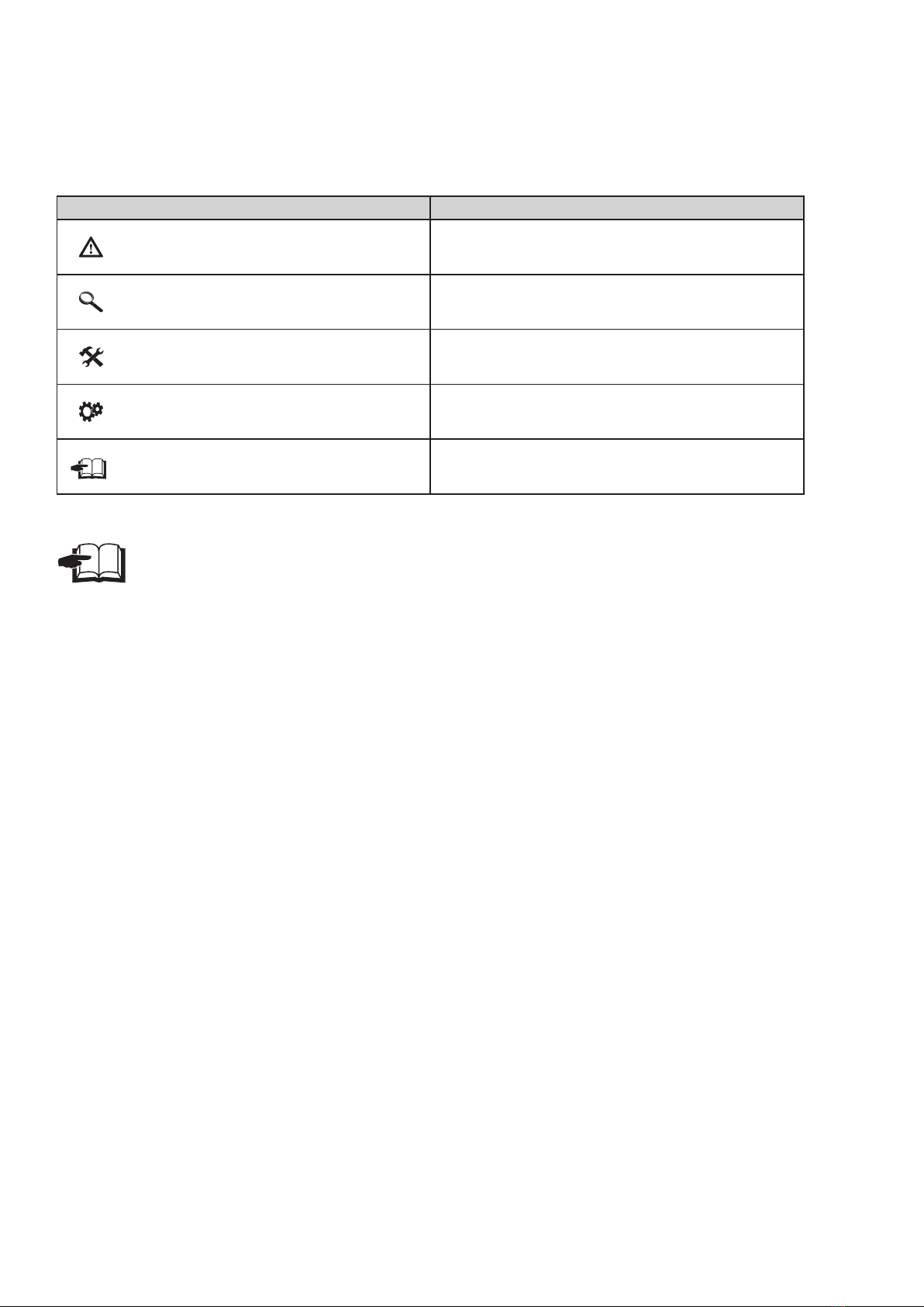
Symbol Meaning
Before installation of the unit, properly read the manual Safe operation of the ventilation
unit. Here you can nd the whole manual on how to use this product safely and properly.
Warning or notice
Important instructions
Practical tips and information
More technical information
Link to another part of the manual
ATTENTION!
IMPORTANT NOTICE!
YOU WILL NEED
TECHNICAL INFORMATION
This manual contains important instructions for the safe installation of the ventilation unit. Before
installation of the ventilation unit, please properly read all the instructions below and follow them!
The manufacturer reserves the right to make changes, including to the technical documentation without
prior notice. Please store this manual for future use, the service manual is a part of the product.
EC CONFORMITY DECLARATION
The product has been designed, manufactured, placed on the market, complies with all applicable regula-
tions and is in compliance with the requirements of the directives of the European Parliament and the Coun-
cil, including amendments to the proposal, under which it was classified.
When handled/operated under normal conditions and in accordance with the instruction manual, the
installation and operation of this product is safe. The harmonized European standards referred to in the
relevant EC declaration of conformity have been applied in the assessment.
For the current and full version of the EC Declaration of Conformity, please refer to the document
package provided at the time of order confirmation.

3
2. UNPACKING
2.1 CHECK THE DELIVERED UNIT 2.2 UNPACK THE UNIT
IMPORTANT NOTICE!
IMPORTANT NOTICE!
● Immediatelyafterreceivingthedelivery,make
anvisualinspectionoftheproduct.Incaseof
visible packaging damage note the damage in
thedeliverynoteandinformthemanufacturer.
● Check whether the delivered type and quanti-
tyof theproducts matchesthe order.In case
of disagreement, do not unpack the unit and
report this to Barkell.
● Ensure that any ancillary items are included.
Thesewillnormallybepackedtogetherwiththe
unitsor inthecaseoflargeitems suchasat-
tenuatorsorducttransitionssuppliedonasep-
aratepallet.
● After unpacking, check whether the unit and
otherpartshavebeensuppliedin goodcondi-
tion.Ifindoubt,contactBarkellaftersalesde-
partmentimmediately.
● All claims for damage or missing goods must
beconrmedinwritingin2workingdaysupon
receiptoftheunitsotherwisetherighttoclaim
willbelost.
● Nevertrytoputadamagedventilationunitinto
operation.
● Ifthe unitis notunpacked immediatelyafter
delivery, it has to be stored in a dry interior
atanambienttemperaturebetween+5°Cand
+35°C.
● Themethodofpackingisforproductstobeloadedonto
pallets(max.2unitsinheight)andfastenedtothemby
means of bolts. A protective lm is added to minimize
wateranddustingress.
● Ensure the securing bolts are unfastened before at-
tempting to remove the unit from the pallet otherwise
permanentdamageofthesupportingbracketsmightoc-
cur.
● Ifthe ventilation unit was transportedattemperatures
below 0°C, it is necessary to leave it in the operating
environmentforatleast2hourswithoutturningonafter
unpacking,fortemperaturecompensationinsidetheunit
tooccur.
This product has to be properly disposed of in accordance with
local laws, regulations and directives.
The product contains batteries, therefore these have to be
recycled or disposed of separately from household waste.
When the battery or product reaches the end of its durability,
contact the distributor or local authorities for information about
recycling options. Separate collection and recycling of your
product and its battery will help to protect natural resources
and ensures that the product will be recycled in such a way that
protects human health and the environment.
3
2.1 CONTRÔLEZ LA LIVRAISON
2. DEBALLAGE
• Lors de la livraison, contrôlez directement si
l'emballage du produit est intact. En cas
d'endommagent de l'emballage, prévenez le
transporteur. Si la réclamation n'est pas déclarée
à temps, une demande ultérieure ne sera plus
acceptée.
• Contrôlez si le type de produit livré correspond à
votre commande. En cas de constatation d'une
différence, ne déballez pas le récupérateur et
prévenez immédiatement le fournisseur.
• Après le déballage, contrôlez l'état des unités et
de tous ses éléments. En cas de doute, adressez-
vous au fournisseur.
• N'utilisez jamais une unité endommagée.
• Si vous ne déballez pas directement le
récupérateur après réception, il devra être
entreposé dans un endroit intérieur sec ayant une
température ambiante de +5 °C à +35 °C.
A LIRE ATTENTIVEMENT!
Tous les matériaux
d'emballage utilisés sont
écologiques et peuvent être
réutilisés ou recyclés.
Participez activement à la
protection de
l'environnement et assurez-
vous que les matériaux
d'emballage sont
convenablement revalorisés.
2.2 DEBALLEZ L'UNITE
• Si l'unité de ventilation a été exposée à des
températures inférieures à 0°C durant le
transport, laissez l'unité déballée à la
température ambiante durant au moins 2 heures
avant de la brancher, pour permettre
l'égalisation de la température dans l'unité de
ventilation.
A LIRE ATTENTIVEMENT!
PLATE BOX
PLATE BOX
1x
8m PLATE BOX
Notice complète
INSTALLATION
PLATE BOX… et PLATE BOX ELEC….
PLATE BOX
Numéro de notice France air
NTE: 1260 A
FR
THERM-X
THERM-X HRFL2
THERM-X HRFL2
3
2.1 CONTRÔLEZ LA LIVRAISON
2. DEBALLAGE
• Lors de la livraison, contrôlez directement si
l'emballage du produit est intact. En cas
d'endommagent de l'emballage, prévenez le
transporteur. Si la réclamation n'est pas déclarée
à temps, une demande ultérieure ne sera plus
acceptée.
• Contrôlez si le type de produit livré correspond à
votre commande. En cas de constatation d'une
différence, ne déballez pas le récupérateur et
prévenez immédiatement le fournisseur.
• Après le déballage, contrôlez l'état des unités et
de tous ses éléments. En cas de doute, adressez-
vous au fournisseur.
• N'utilisez jamais une unité endommagée.
• Si vous ne déballez pas directement le
récupérateur après réception, il devra être
entreposé dans un endroit intérieur sec ayant une
température ambiante de +5 °C à +35 °C.
A LIRE ATTENTIVEMENT!
Tous les matériaux
d'emballage utilisés sont
écologiques et peuvent être
réutilisés ou recyclés.
Participez activement à la
protection de
l'environnement et assurez-
vous que les matériaux
d'emballage sont
convenablement revalorisés.
2.2 DEBALLEZ L'UNITE
• Si l'unité de ventilation a été exposée à des
températures inférieures à 0°C durant le
transport, laissez l'unité déballée à la
température ambiante durant au moins 2 heures
avant de la brancher, pour permettre
l'égalisation de la température dans l'unité de
ventilation.
A LIRE ATTENTIVEMENT!
PLATE BOX
PLATE BOX
1x
8m PLATE BOX
Notice complète
INSTALLATION
PLATE BOX… et PLATE BOX ELEC….
PLATE BOX
Numéro de notice France air
NTE: 1260 A
FR

4
3. MAJOR PARTS
Fan
Mains isolator
Control panel
Service access to the unit
Central panel - Access to PHE
Side panels - Access to filters,
fans and coils
Filters
Supply: F7
Extract: G4
THERM-X
HRFL II 040/070/150/200
Delivered with the product:
1 x Touchscreen Controller
Note: Cabling not included, UTP cable
recommended
The cable length should not exceed 50 m (0.5
mm2)
1 x Room Temperature Sensor
Note:
Sensor supplied loose, cabling not included
Note:
All HRFL II ceiling mounted units are supplied with F7 and M5 filters as standard. If a different filter grade is
selected the filter is supplied loose for replacement on site by others.
AV & Hanging Brackets
PHE
Condensate drain
MUST BE TRAPPED

5
4. DIMENSIONS
OTA
EHA
SUP
ETA
OTA - Outside air
SUP - Supply air
ETA - Extract air
EHA - Exhaust air
THERM-X
HRFL II 040/070/150/200
Type H h a B b i j K k c d C D X x Y y Zz condensate ø
HRFL2-040 780 670 1190 310 300 1120 700 485 21 250 150 274 174 166 166 332 332 166 166 18
HRFL2-070 1080 970 1400 310 300 1330 1000 590 21 300 200 324 224 242 242 517 517 242 242 18
HRFL2-150 1385 1270 1700 390 380 1630 1305 720 21 500 250 524 274 323 323 625 625 323 323 18
HRFL2-200 1710 1600 2000 470 460 1430 1630 902 21 600 300 624 324 433 433 735 735 433 433 18
a
b
B
K
k
18
2x1/2"
C
D
c
d
h
i
j
H
x z
X
Z
Y
y
INDOOR ENVIROMENT
OUTDOOR ENVIROMENT
a
b
B
K
k
18
2x1/2"
C
D
c
d
h
i
j
H
x z
X
Z
Y
y
INDOOR ENVIROMENT
OUTDOOR ENVIROMENT
All sizes in mm
C
22
AB
B
A
AA
D
E
EE
DD
A B
C D
E
DD
EE AB AA
MODUL-400
334 470 295 250 150 274 174 366 397
MODUL-800
484 470 300 300 200 324 224 516 547
MODUL-1600
636 470 380 500 250 524 274 668 699
MODUL-2500
800 470 460 600 300 624 324 832 863
THERM-X
HRFL II 040/070/150/200
WCO (Changeover)/DX (Direct Expansion) external module
Type A B C D E DD EE AB AA condensate ø WCO connection
HRFL2-400 334 470 295 250 150 274 174 366 397 22 3/4“
HRFL2-700 484 470 300 300 300 324 224 516 547 22 3/4“
HRFL2-1500 636 470 380 500 500 524 274 668 699 22 3/4“
HRFL2-2000 800 470 460 600 600 624 324 832 863 22 3/4“

6
5. TECHNICAL SPECIFICATIONS
Model without electric pre-heating coil and...
...without coil / with water heating coil / with WCO coil / with DX coil
Model with electric pre-heating coil and...
...without coil / with water heating coil / with WCO coil / with DX coil
Characteristics of the fan electric motor (per fan)
Characteristics of LPHW coil
* For water temperature gradient 60/40 and inlet air temperature 15°C
...electric post heating coil
...electric post heating coil
Characteristics of electric preheater coil
Type Voltage [V] Frequency [Hz] Rated power [kW] Rated current [A]
HRFL2-040 230 50 0.34 2.7
HRFL2-070 230 50 0.33 2.5
HRFL2-150 230 50 1 5.6
HRFL2-200 230 50 1 6.3
Type Voltage [V] Frequency [Hz] Rated power [kW] Rated current [A]
HRFL2-040 230 50 0.9 4.1
HRFL2-070 230 50 1.8 8.8
HRFL2-150 400 50 3.7 18
HRFL2-200 400 50 5.8 13.5
Type Voltage [V] Frequency [Hz] Rated power [kW] Rated current [A]
HRFL2-040 230 50 1.7 7.4
HRFL2-070 230 50 3.1 13.5
HRFL2-150 400 50 6.3 14.7
HRFL2-200 400 50 9.4 19.8
Type Voltage [V] Frequency [Hz] Rated power [kW] Rated current [A]
HRFL2-040 230 50 2.7 11.8
HRFL2-070 400 50 4.5 11.7
HRFL2-150 400 50 9 18
HRFL2-200 400 50 14.2 24.8
Type Phase [pcs] Voltage [V] Frequency [Hz] Rated power [W] Rated current [A] Speed [r/min] Protection IP Insulation class
HRFL2-040 1 230 50 169 1.35 4120 54 B
HRFL2-070 1 230 50 175 1.3 2800 44 B
HRFL2-150 1 230 50 455 3.1 2600 54 B
HRFL2-200 1 230 50 500 3.15 1970 54 B
Type Phase [pcs] Voltage [V] Frequency [Hz] Rated power [kW] ∆ T [°C]
HRFL2-040 1 230 50 1.1 6.3
HRFL2-070 1 230 50 1.6 6.3
HRFL2-150 1 230 50 2.7 5.3
HRFL2-200 3 400 50 4.8 6.3
Type Phase [pcs] Voltage [V] Frequency [Hz] Rated power [kW] ∆ T [°C]
HRFL2-040 1 230 50 1.35 10
HRFL2-070 1 230 50 2.7 10
HRFL2-150 3 400 50 5.3 10
HRFL2-200 3 400 50 8.4 10
Type Rated capacity *[kW] Water pressure loss [kPa] Air pressure loss [Pa] Connections diameter Air fl w [m³/h]
HRFL2-040 1.75 1 10 1/2“ 400
HRFL2-070 2.71 3 15 1/2“ 700
HRFL2-150 5.92 17 27 1/2“ 1500
HRFL2-200 9.22 9 21 1/2“ 2000
Characteristics of electric post heating coil
NOTE: Please note all performance data is displayed for reference only. Coil performance is based on the nominal conditions stated and should be
checked for the actual operational conditions of the equipment at the time of selection.

7
* For water temperature gradient 7/12 and inlet air temperature 25°C with 70% of relative humidity.
Characteristics of water changeover cooling / heating coil (WCO) - Heating
* For water temperature gradient 60/40 and inlet air temperature 15°C.
Characteristics of water changeover cooling / heating coil (WCO) - Cooling
Characteristics of direct expansion coil (DX)
Type Rated capacity [kW]* Water pressure loss [kPa] Air pressure loss [Pa] Connection diameter Air fl w [m³/h]
HRFL2-040 2.51 0.29 80 3/4“ 400
HRFL2-070 4.6 0.59 71 3/4“ 700
HRFL2-150 9.41 0.69 99 3/4“ 1500
HRFL2-200 15.7 1.67 83 3/4“ 2000
Type Rated capacity
[kW]*
Water pressure loss
[kPa]
Air pressure loss
[Pa] Connection diameter Air fl w [m³/h]
HRFL2-040 1.94 2.65 91 3/4“ 400
HRFL2-070 3.68 5.4 80 3/4“ 700
HRFL2-150 7.34 6.57 112 3/4“ 1500
HRFL2-200 12.62 15.79 94 3/4“ 2000
Type Airfl w
[m³/h]
Power*
[kW]
Temperature behind the direct
evaporator [°C]RH [%] Fluid pressure loss
[kPa]
Air pressure loss
[Pa]
Connection
[gas]
Connection
[fluid
HRFL2-040 400 2.54 10 92 11 79 1/2“ 1/2“
HRFL2-070 700 4.65 10 92 41 69 1/2“ 5/8“
HRFL2-150 1500 9.94 10 92 12 97 1/2“ 7/8“
HRFL2-200 2000 16.15 10 92 28 91 3/4“ 7/8“
* For inlet air temperature 27°C with 70% of relative humidity and evaporation temperature 5°C, refrigerant R410A.
NOTE: Please note all performance data is displayed for reference only. Coil performance is based on the nominal conditions stated and should be
checked for the actual operational conditions of the equipment at the time of selection.

8
• The unit is not designed for air containing am mable
or explosive mixtures, chemical vapours, heavy
dust, soot, grease, toxins, pathogenic or ganism, etc.
• The degree of IP protection of the product is IP 20
when ducted (protection against objects bigger than
12.5 mm, does not protect against water!).
6.1-1 Access distances required for
unit service
6. INSTALLATION
6.1 CHOOSE THE PLACE OF
INSTALLATION
• Theunithastobeoperatedonlyinadry
environmentandprotectedagainstexternal
atmosphericconditionswithanambient
temperaturefrom+5°Cto+35°C.
The temperature of the inlet air should be in the
range from -20 °C to +60 °C and humidity up to
90%.
TECHNICAL INFORMATION
All the dimensions listed in the table are in mm
Type A
HRFL2-040
310
HRFL2-070
360
HRFL2-150
460
HRFL2-200
560
•Before installing the units in position ensure that
there is suitable access for connecting all services.
•The design of the ceiling must provide for access to
the unit units for commissioning and maintenance.
•The minimum distances for servicing the unit are
portrayed below.
60
750 mm
100 mm
0 mm
A

9
● AlltheHRFL IIunitsmustbeplacedinthehori-
zontalposition.Anyotherpositionisprohibited.
● Theunitmustbeinstalledinsuchawaysothat
the direction of the air inlet and outlets corre-
spondswiththeaircirculationinthedistribution
ductwork.
● Theremustalsobeadequateaccesstotheunits
oncetheyareinstalledforroutinemaintenance
and the removal of access panels and internal
componentssuchasfans,filters,plateheatex-
changer,coilsanddraintrays.
● Accessspacemustbeprovidedprimarilytoal-
lowremovalofthebottom panels,controlpanel
lidandallowelectricaland pipingconnectionsto
theservicesideofthe units.
TECHNICAL INFORMATION
● Allmaterialsusedatadistancelessthan100mm
from the ventilation unit have to be non-am-
mable (do not burn, ame up, burn down) or
onlyslightly ammable (donotburn,fallapart
– e.g. plasterboard). However, these materials
mustnotcovertheinletandoutletopeningsof
theunit.
● The safe distance of ammable materials from
theunitopeningsis500mm.
● Thesafedistance of ammable materialsin all
otherdirectionsis100mm.
6.1-2 Safe installation distance
ATTENTION!
6. INSTALLATION
10
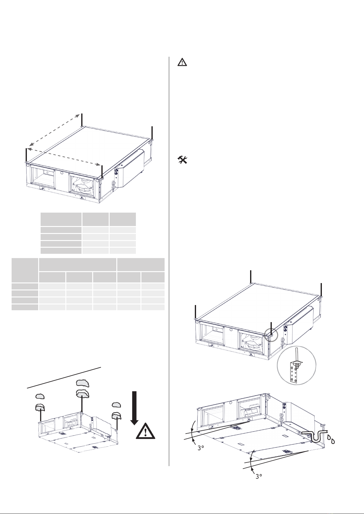
6.1-3 Hanging the unit
For location of the anchorage points, use the drill-
ing template listed below.
The units are equipped with mounting brackets
which should be used in conjunction with threaded
drop rods ZTZ-M8/1.0 or equivalent to facilitate
levering and leveling.
• Duetotheweightoftheunit,itisnecessaryto
useanappropriateliftingdevicewhenassem-
bling(e.g.aforklift,scissorlift,etc...)
• It’srecommendedthattheunitisinstalledinto
position before making connections to duct
andpipeworkorelectricalconnections.
• Depending on the type of building structure
there can be a number of ways of attaching
thesuspensionsystem,suchasdrilled-inx-
ings,clampsandclips,wedgenuts,etc..En-
sure whatever system is utilized it has su-
cientstrengthtosupporttheunit.
• 4-6M8checknuts(accordingtotheunittype)
• 4-6studbolts
• 4-6 dowels of a suitable type and dimension
(accordingtotheceilingmaterialandtheunit
weight)
• Drillerwithdrillsofasuitabletypeanddimen-
sion
• Tongsandnutwrenches
Place the unit horizontally and then incline it by 3°
by adjusting the nuts on the drop rods so that the
condensate drains into the outlet connection on
the access side of the unit.
ATTENTION!
YOU WILL NEED
6. INSTALLATION
Establish the weight of each unit and make sure
that ceiling will be adequate to support up to four
times the weight of the unit.
Drill the holes in the ceiling, try the strength of its
material and attach the unit by the side brackets
using the hanging rods ZTZ-M8/1.0 or equivalent.
A
B
Type A B
HRFL2-040 700 1120
HRFL2-070 1000 1330
HRFL2-150 1300 1630
HRFL2-200 1630 1930
Type
Weight of unit (kg) Weight of accesso-
ries (kg)
Without
reheating
With electric
reheating
With water
reheating
WCO mod-
ule DX module
HRFL2-040 70 75 75 25.5 24
HRFL2-070 90 95 95 32 30
HRFL2-150 165 170 170 37 35
HRFL2-200 240 245 245 43 40

11
X
6. INSTALLATION
6.2-1 Rectangular to circular
transition
6.2 CONNECTING THE DUCTING
NOTE: This is an accessory and must be ordered
separately
Example of possible connection with flexible connectors.
NOTE: Barkell does not supply the accessories portrayed
above as standard
YOU WILL NEED
• Theconnectedductworkmusthavethesamedi-
mensionsastheinletandoutletopeningsofthe
ventilationunits.Inthecaseofasmallerdiame-
terofductwork,turbulencemightoccurresulting
onareductionoftheuniteciencyandlifetime.
• Connecttheinletandoutletopenings(rectangu-
lartocircular transition) using exiblejoints to
avoidvibrationsandensurethattheseareprop-
erlyalignedwiththeductwork.
• All ductwork must be supported independently
fromtheunit.
• Flexiblecorrugatedductingcanimposehighre-
sistances if formed into tight bends and should
thereforebeavoided.
All the dimensions are in mm
IMPORTANT NOTICE!
• 16M8screws
• 4pcsofrectangulartocirculartransitions( accessory
can be acquired from Barkell)
• appropriatenutwrenches
• sealingtape/sealant
Type X Y D L M F
HRB-PR-01 250 150 200 150 50 20
HRB-PR-02 300 200 250 200 50 20
HRB-PR-03 500 250 315 250 70 20
HRB-PR-04 600 300 400 300 70 20
Ductwork should be connected to the inlets and outlets
of the unit by means of a transition piece.
NOTE: Barkell does not supply the accessories portrayed
above as standard
Connections to the distribution ductwork should be
made using suitable clamps or clips ensuring that an
airtight joint is made and the ductwork then
insulated and taped down. The minimum distance
between any ductwork bends or the adapters and
the unit outlets is 500 mm.
SUP
EHA
ETA
OTA
OTA - Outside air
SUP - Supply air
ETA - Extract air
EHA - Exhaust air

12
6. INSTALLATION
NOTE: Barkell does not supply the accessories
portrayed above as standard
NOTE: Barkell does not supply the accessories
portrayed above as standard. These accessories
must be ordered and are supplied loose for
installation and wiring by others.
6.2-2 Protection of the unit
openings
(Not a part of the delivery)
6.3 CONNECTION OF THE
If an opening of the unit is not connected to the
ductwork, an metallic mesh in accordance with the
Machinery Directive Requirements or similar pro-
tection must be used to avoid the contact of water
and moving solid particles with the fan, heating
coils etc.
MECHANICAL ACCESSORIES
6.3-1 Shut-off dampers
These rectangular shut-off dampers are used for
shutting off the ductwork connected to the ven-
tilation unit.
●
2rectangularshutodampers(accordingtotheunit
model)
● 2actuators(withoneortwowires230V)
● 8M8screwsandnuts
● 16washers
● correspondingnutwrench
● aatheadandcross-pointscrewdriver,sealingtape
andsealant
YOU WILL NEED
Attach the damper to the ductwork at a distance of
around 2 m ahead of the fresh air inlet opening and to
the outlet ductwork at a distance of around 2 m from
the outlet opening. Install the actuators on the damper
shafts and to the corresponding connectors in the con-
trol housing. See chapter Connection of the electri-
cal wiring and the electrical equipment.
Adjust the damper in such a way that it is fully closed
when the unit is turned o and fully opened when the
unit is in operation. Other arrangements may damage
the unit.
Technical details of the MLKR Shut-Off damper
ATTENTION!
If the unit openings are un-ducted during op-
eration there is a potential risk of injury due
to rotating parts and heat surfaces inside the
unit.
•The anged damper frame is manufactured ofgal-
vanized steel.
•The blades are made of aluminum.
Unit type Rectangular damper A B
HRFL2-040 MLKR/S-250150 250 150
HRFL2-070 MLKR/S-300200 300 205
HRFL2-150 MLKR/S-500250 500 255
HRFL2-200 MLKR/S-600300 600 305
10mm
13
6. INSTALLATION
Technical details of the KRTK-A Shut-Off damper
Produced in EU
COMPONENTS КОМПОНЕНТЫ
The company reserves the right of change without previous announcement. ©2VV, spol. s r.o.
451
Your partner in ventilation...
- Diameters: 100, 125, 150, 160, 200, 250, 315, 355 mm
- Manual or servo drive control
The KRTK-A shutting flap is designed for tight closing of
individual branches in HVAC systems. The flap is designed
for operation in the basic environment for conveying air
free of rough dust, grease, chemical fumes, and other
contaminants. The flap housing is made of galvanized
plate. The flap may be fitted with a servo drive after
removing the manual control lever.
BASIC FEATURES
- диаметры: 100, 125, 150, 160, 200, 250, 315, 355 мм
- управление ручное или посредством сервопривода
Запорный клапан KRTK-A предназначен для
герметичного закрытия отдельных воздуховодов
вентиляционных систем. Клапан предназначен для
эксплуатации в основной среде и устанавливается
в системах, в которых движется воздух без грубой пыли,
жиров, химических испарений и других загрязнений.
Корпус клапана изготовлен из оцинкованного листа.
После демонтажа рычага ручного управления можно
оборудовать клапан сервоприводом.
КРАТКАЯ ХАРАКТЕРИСТИКА
PRIMARY PARAMETERS ГЛАВНЫЕ ПАРАМЕТРЫ
KRTK-A
Type
Тип
KRTK-A-100
KRTK-A-125
KRTK-A-150
KRTK-A-160
KRTK-A-200
KRTK-A-250
KRTK-A-315
KRTK-A-355
Weight [kg]
Bес [кг]
0,4
0,6
0,7
1,0
1,4
2,1
3,6
5,1
D L L1L2
40
40
40
40
40
60
60
60
200
200
200
200
200
200
200
300
280
280
280
280
280
320
320
420
100
125
150
160
200
250
315
355
Dimensions [mm]
Размеры [мм]
L
h
L1
L2L2
iD
Sheet thickness [mm]
Толщиналиста
[мм]
0,55
0,55
0,55
0,55
0,55
0,80
0,80
0,80
h
76
73
71
70
67
65
64
63
•The damper housing is manufactured of galvanized
steel.
•
The damper may be tted with a actuator after
removing the manual control lever.
10mm
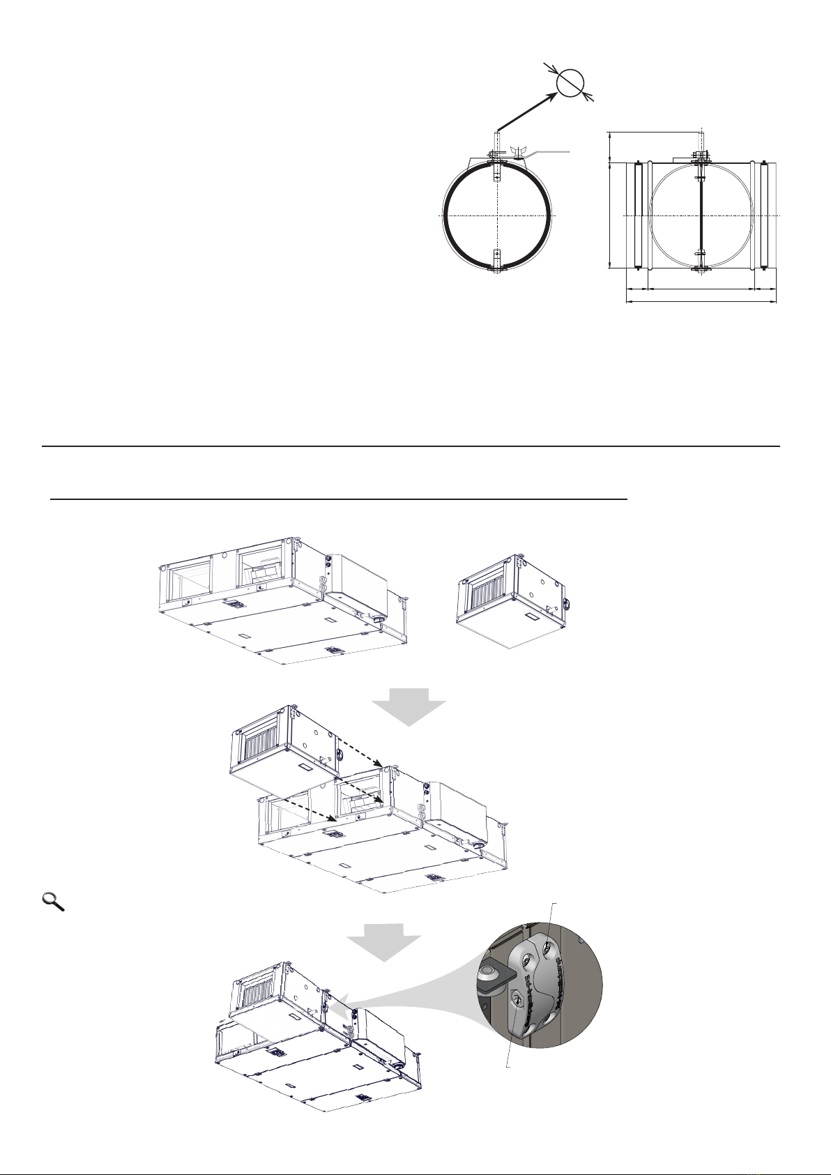
INSTALLATION OF EXTERNAL WCO, DX MODULE (accessories)
MODUL
JEDNOTKA
3D-Intelliclamp
4 x SR-ISO7380-5,0x25
(NA 1 UZAVER 3D-Intelliclamp)
A
DETAIL A
MĚŘÍTKO 1 : 1
SR-ISO7380-5,0x25
M8x35 DIN 912
e external
module includes
sensors(water and
air temperature),
PE ground-ing
conductor and
fasteners.
Unit type Circular damper Dimensions [mm]
D L L
1
L
2
h
HRFL2-040 KRTK-A-200 200 280 200 40 67
HRFL2-070 KRTK-A-250 250 320 200 60 65
HRFL2-150 KRTK-A-315 315 320 200 60 64
HRFL2-200 KRTK-A-400 400 520 300 60 65
NOTE: Damper actuators not
supplied with damper as standard.
These accessories must be
ordered and are supplied loose
for installation and wiring by others.
NOTE: External modules include a condensate
connection. This connection MUST BE
TRAPPED!
NOTE: Water coil valves/actuators are not
included as standard.
These accessories must be ordered and are
supplied loose for installation and wiring by
others.
NOTE: On units equipped with changeover
water heat exchangers it is recommended a 3
way diverting valve piping arrangement. If a 2
way valve must be used the length of the
pipework must be assessed in advance to avoid
issues with the method of control of the heat
exchanger.
OBSOLETE
14
6.4. CONNECTION OF THE
ELECTRICAL WIRING AND
THE ELECTRICAL
ACCESSORIES
ATTENTION!
●The main isolator switch of the electric
power supply must be turned off before
any intervention to the ventilation unit!
●Main supply voltages (220-240/400V)
present on this equipment might cause
death or serious injury by electric shock
● Theelectricalwiringoftheventilationunitmust
be executed according to the design by a
profes-sional electrician. The electrical wiring
mustbe realizedbyapersonauthorizedforthe
perform-ingofelectricalwirings.Itisnecessary
to follow all instructions of this manual as well
aslocal lawsandregulations.
● Thewiring diagrams listed on theproduct take
priorityoverdiagramslistedinthismanual!Be-
forewiringtheproduct,checkwhetherthecon-
nectormarkings corresponds tothe diagram. If
in doubt, contact the supplier and do not wire
theunitinanycase.
● Iftheproductisconnectedtoanothercontrol
systemthantheoriginalcontrolsystem,contact
thecompanythatsuppliedthissystemforin-
formationregardingtheelectricalwiringofthe
measuringsensorsandcontrols.
● Theunitmustbeconnectedtothepowersupply
lineusingarigidheatresistantisolatedcableof
adiameterthatcorrespondstothevalidlocal
regulations.
● Forpreservationoftheelectricalprotection,all
thecablesmustpassthroughthesideopenings
ofthecontrolhousing.
● Anyinterventionsormodificationsoftheinner
electricalwiringoftheunitareprohibitedand
leadtothelossofthewarranty!
● Theproperfunctionoftheunitcanbeguaran-
teedonlywhenusingtheoriginalaccessories.
● Ifitisnecessarytoplaceasensororaregulat-
ingcomponentinsidetheunitoronitscover,
consultitsplacementwiththeunitmanufacturer
(oritsrepresentative).
● Donotoverloadextensioncablingandwallout-
letsasthismightresultinariskoffireor electric
shock.
● Theunitmustbecorrectlyearthedtoavoidover
currentandearthfaultprotection.

15
All phases of the electric power supply must be
connected through a corresponding type of
circuit breaker. The distance between open
contacts must be greater than 3 mm.
The unit must be wired in such a way that it can
be disconnected from the electric power supply
using a single switch.
The unit must be connected to TN-S network, this
means that the neutral conductor must always be
connected.
I = current
P =
m = weight
IP =
ver = version
Product type data
U = voltage
F = frequency
n = fan speed
ph =
av = airow
Serial number
power/
absorber power
electrical
protection
number of
phases
6. INSTALLATION
Recommended cable and circuit breaker
sizes
Model with electric pre-heating coil
Model with electric post heating coil
Model with electric pre-heating and post heating coil
Recommended values. values must be specified by the person responsible
for the wiring in the building (e.g. designer) with regard to parameters of
the power line wiring and other parameters of the building
Recommended values. values must be specified by the person
responsible for the wiring in the building (e.g. designer) with regard to
parameters of the power line wiring and other parameters of the building
Recommended values. values must be specified by the person
responsible for the wiring in the building (e.g. designer) with regard to
parameters of the power line wiring and other parameters of the building
Number of
phases
Number of
phases
Number of
phases
Voltage (V)
Voltage (V)
Voltage (V)
Power (W)
Power (W)
Power (W)
Current (A)
Current (A)
Current (A)
Cable type*
Cable type*
Cable type*
Circuit breaker
type (A)*
Circuit breaker
type (A)*
Circuit breaker
type (A)*
HRFL2-040
HRFL2-070
HRFL1-150
HRFL1-200
HRFL2-040
HRFL2-070
HRFL1-150
HRFL1-200
HRFL2-040
HRFL2-070
HRFL1-150
HRFL1-200
1
1
3
3
1
1
1
3
1
3
3
3
230
230
400
400
230
230
230
400
230
400
400
400
1700
3100
6300
9400
900
1800
3700
5800
2700
4500
9000
14200
7,4
13,5
14,7
19,8
4,1
8,8
18
13,5
11,8
11,7
18
24,8
?
?
?
?
?
?
?
?
?
?
?
?
?
?
?
?
?
?
?
?
?
?
?
?
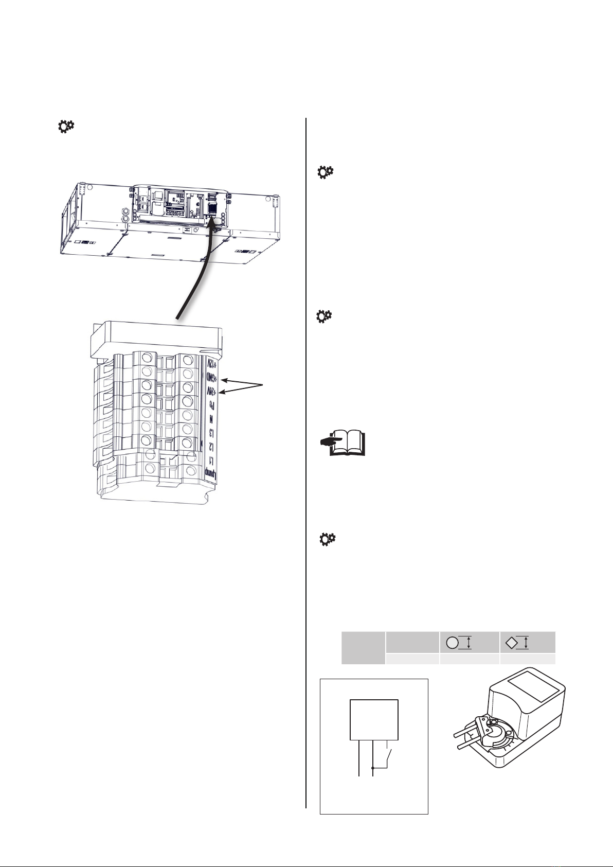
6.4-1 The power supply cable
The connecting terminal for the power supply ca-
ble is placed in the control device housing.
Minimum size of the protective grounding lead
must be in compliance with local safety regula-
tions for heavy current through the lead of the
protective grounding of the device.
● Theparametersoftheelectricalwiringarelisted
onthecontroldevicehousinglabel.
TECHNICAL INFORMATION
Pe
L1 L2 L3 N
ATTENTION!

16
6. INSTALLATION
6.4-2 – Electrical accessories
Electrical accessories must be connected to the terminals located in the control panel according to the
wiring diagram and the markings on the terminals.
NOTE: The wiring diagrams present on the units control box take precedence over the provided wiring
diagrams.
Control panel
1
1. 1
5.
1
6.
1
2.
1
7.
1
8.
1
9. 1
10. 1
11. 1
12. 1
13. 1
14. 1
15. 1
16. 1
17.
1
3. 1
4.
1
20. 1
21. 1
22.
1
18. 1
19.
EN RU CZ
1. A (5-6) LF1 - FLAP INLET (output L-open), LF2 - FLAP OUTLET ( output L-open) LF1 ( L-), LF2 - ( L-) LF1 - KLAPKA PŘÍVOD (výstup L-open), LF2 - KLAPKA ODVOD ( výstup L-open)
2. A (7-8) RUN CONTACT (output -NO/NC settable) RUN ( - NO/NC ) RUN KONTACT (výstup -NO/NC nastavitelné)
3. A (9-10) ERROR CONTACT (output NO) ( NO) ERROR KONTACT (výstup NO)
4. A (11-12) PREHEATER WATER PUMP (11 - Lint, 12 - Lout) (11 - Lint,12 - Lout) VODNÍ ČERPADLO PŘEDEHŘEVU (11 - Lint, 12 - Lout)
5. A (13-14) BOOST (input NO) BOOST ( NO) BOOST (vstup NO)
6. A (15-16) FIRE (input NC) FIRE - ( NC) FIRE (vstup NC)
7. A (17-18) EXTERNAL CONTROL ON/OFF (input NC) ON/OFF ( NC) EXTERNÍ OVLÁDÁNÍ ON/OFF (vstup NC)
8. A (18-19) AQS SENSOR 0-10V (input) 0-10 () ČIDLO KVALITY VZDUCHU 0-10V (vstup)
9. B (1-2) WATER PUMP (1 - Lint, 2 - Lout) (1 - Lint, 2 - Lout) VODNÍ ČERPADLO (1 - Lint, 2 - Lout)
10. B (3-4) HEAT PUMP CONTROL settable (output - ON/OFF) ( - ON/OFF) ŘÍZENÍ TEPELNÉHO ČERPADLA nastavitelné (výstup - ON/OFF)
11. B (5-6) ADIABATIC MODULE output - ON/OFF ( - ON/OFF) ADIABATICKÝ MODUL výstup - ON/OFF
12. B (7-8) COOL / HEAT settable (CO = NC/NO - DX = output settable) / (CO = NC/NO - DX = ) CHLAZENÍ / TOPENÍ nastavitelné (CO = NC/NO - DX = výstup nastavitelné)
13. B (9-10) ADIABATIC MODULE ERROR input NO ERROR ( NO) ADIABATICKÝ MODUL ERROR vstup NO
14. B (11-12) HEAT PUMP DEFROST settable (input NC/NO) ( NC/NO) ODMRAŽOVÁNÍ TEPELNÉHO ČERPADLA nastavitelné (vstup NC/NO)
15. B (13-14) HEAT PUMP ERROR settable (input NC/NO) ( NC/NO) CHYBA TEPELNÉHO ČERPADLA nastavitelné (vstup NC/NO)
16. B (15-16) PIR (input NC) PIR ( NC) POHYBOVÉ ČIDLO PIR (vstup NC)
17. B (17-18) CONDENSATE OVERFLOW (input NC) ( NC) ČIDLO PŘETEČENÍ KONDENZÁTU (vstup NC)
18. B (46-47) EXTERNAL TEMPERATURE SENSOR (external postheater - input) ( - ) EXTERNÍ TEPLOTNÍ ČIDLO (externí dohřev - vstup)
19. B (44-45) EXTERNAL TEMPERATURE SENSOR (adiabatic module / recirc. chamber - input) ( / - ) EXTERNÍ TEPLOTNÍ ČIDLO (adiabatický modul / recirkulační komora - input)
20. B (38-39) EXTERNAL PREHEATER (output - Water= 0-10V, electric=PWM) ( - =0-10, =PWM) EXTERNÍ PŘEDEHŘEV (výstup - vodní=0-10V, elektrický=PWM)
21 B (36-37) EXTERNAL POSTHEATER (output - Water= 0-10V, electric=PWM) ( - =0-10, =PWM) EXTERNÍ DOHŘEV (výstup - vodní=0-10V, elektrický=PWM)
22 B (34-35) RECIRCULATION CHAMBER (output 0-10V) ( 0-10) RECIRKULAČNÍ KOMORA (výstup 0-10V)
A
B
Control panel
1
1. 1
5. 1
6.
1
2. 1
7.
1
8.
1
9. 1
10. 1
11. 1
12. 1
13. 1
14. 1
15. 1
16. 1
17.
1
3. 1
4.
1
20. 1
21. 1
22.
1
18. 1
19.
EN RU CZ
1. A (5-6) LF1 - FLAP INLET (output L-open), LF2 - FLAP OUTLET ( output L-open) LF1 ( L-), LF2 - ( L-) LF1 - KLAPKA PŘÍVOD (výstup L-open), LF2 - KLAPKA ODVOD ( výstup L-open)
2. A (7-8) RUN CONTACT (output -NO/NC settable) RUN ( - NO/NC ) RUN KONTACT (výstup -NO/NC nastavitelné)
3. A (9-10) ERROR CONTACT (output NO) ( NO) ERROR KONTACT (výstup NO)
4. A (11-12) PREHEATER WATER PUMP (11 - Lint, 12 - Lout) (11 - Lint,12 - Lout) VODNÍ ČERPADLO PŘEDEHŘEVU (11 - Lint, 12 - Lout)
5. A (13-14) BOOST (input NO) BOOST ( NO) BOOST (vstup NO)
6. A (15-16) FIRE (input NC) FIRE - ( NC) FIRE (vstup NC)
7. A (17-18) EXTERNAL CONTROL ON/OFF (input NC) ON/OFF ( NC) EXTERNÍ OVLÁDÁNÍ ON/OFF (vstup NC)
8. A (18-19) AQS SENSOR 0-10V (input) 0-10 () ČIDLO KVALITY VZDUCHU 0-10V (vstup)
9. B (1-2) WATER PUMP (1 - Lint, 2 - Lout) (1 - Lint, 2 - Lout) VODNÍ ČERPADLO (1 - Lint, 2 - Lout)
10. B (3-4) HEAT PUMP CONTROL settable (output - ON/OFF) ( - ON/OFF) ŘÍZENÍ TEPELNÉHO ČERPADLA nastavitelné (výstup - ON/OFF)
11. B (5-6) ADIABATIC MODULE output - ON/OFF ( - ON/OFF) ADIABATICKÝ MODUL výstup - ON/OFF
12. B (7-8) COOL / HEAT settable (CO = NC/NO - DX = output settable) / (CO = NC/NO - DX = ) CHLAZENÍ / TOPENÍ nastavitelné (CO = NC/NO - DX = výstup nastavitelné)
13. B (9-10) ADIABATIC MODULE ERROR input NO ERROR ( NO) ADIABATICKÝ MODUL ERROR vstup NO
14. B (11-12) HEAT PUMP DEFROST settable (input NC/NO) ( NC/NO) ODMRAŽOVÁNÍ TEPELNÉHO ČERPADLA nastavitelné (vstup NC/NO)
15. B (13-14) HEAT PUMP ERROR settable (input NC/NO) ( NC/NO) CHYBA TEPELNÉHO ČERPADLA nastavitelné (vstup NC/NO)
16. B (15-16) PIR (input NC) PIR ( NC) POHYBOVÉ ČIDLO PIR (vstup NC)
17. B (17-18) CONDENSATE OVERFLOW (input NC) ( NC) ČIDLO PŘETEČENÍ KONDENZÁTU (vstup NC)
18. B (46-47) EXTERNAL TEMPERATURE SENSOR (external postheater - input) ( - ) EXTERNÍ TEPLOTNÍ ČIDLO (externí dohřev - vstup)
19. B (44-45) EXTERNAL TEMPERATURE SENSOR (adiabatic module / recirc. chamber - input) ( / - ) EXTERNÍ TEPLOTNÍ ČIDLO (adiabatický modul / recirkulační komora - input)
20. B (38-39) EXTERNAL PREHEATER (output - Water= 0-10V, electric=PWM) ( - =0-10, =PWM) EXTERNÍ PŘEDEHŘEV (výstup - vodní=0-10V, elektrický=PWM)
21 B (36-37) EXTERNAL POSTHEATER (output - Water= 0-10V, electric=PWM) ( - =0-10, =PWM) EXTERNÍ DOHŘEV (výstup - vodní=0-10V, elektrický=PWM)
22 B (34-35) RECIRCULATION CHAMBER (output 0-10V) ( 0-10) RECIRKULAČNÍ KOMORA (výstup 0-10V)
AB
F1 2A
1. A (5-6) LF1 - INTAKE DAMPER (output L-open), LF2 – EXHAUST DAMPER (output L-open)
2. A (7-8) RUN CONTACT (output NO/NC adjustable)
3. A (9-10) ERROR CONTACT (output NO)
4. A (11-12) PREHEATING WATER PUMP (11 - Lint, 12 - Lout)
5. A (13-14) BOOST (input NO)
6. A (15-16) FIRE (input NC)
7. A (17-18) EXTERNAL CONTROL ON/OFF (input NC)
8. A (18-19) Air quality sensor 0-10V (input)

17
6. INSTALLATION
READ CAREFULLY!
●The wiring diagrams present on the units control box take precedence over the provided wiring diagrams.
● Accessoriesmustbeconnectedwithacableweprovideorwithacableappropriatetothespecifications
of thecomponent.
Control panel
1
1. 1
5. 1
6.
1
2. 1
7.
1
8.
1
9. 1
10. 1
11. 1
12. 1
13. 1
14. 1
15. 1
16.
1
17.
1
3. 1
4.
1
20. 1
21. 1
22.
1
18. 1
19.
EN RU CZ
1. A (5-6) LF1 - FLAP INLET (output L-open), LF2 - FLAP OUTLET ( output L-open) LF1 ( L-), LF2 - ( L-) LF1 - KLAPKA PŘÍVOD (výstup L-open), LF2 - KLAPKA ODVOD ( výstup L-open)
2. A (7-8) RUN CONTACT (output -NO/NC settable) RUN ( - NO/NC ) RUN KONTACT (výstup -NO/NC nastavitelné)
3. A (9-10) ERROR CONTACT (output NO) ( NO) ERROR KONTACT (výstup NO)
4. A (11-12) PREHEATER WATER PUMP (11 - Lint, 12 - Lout) (11 - Lint,12 - Lout) VODNÍ ČERPADLO PŘEDEHŘEVU (11 - Lint, 12 - Lout)
5. A (13-14) BOOST (input NO) BOOST ( NO) BOOST (vstup NO)
6. A (15-16) FIRE (input NC) FIRE - ( NC) FIRE (vstup NC)
7. A (17-18) EXTERNAL CONTROL ON/OFF (input NC) ON/OFF ( NC) EXTERNÍ OVLÁDÁNÍ ON/OFF (vstup NC)
8. A (18-19) AQS SENSOR 0-10V (input) 0-10 () ČIDLO KVALITY VZDUCHU 0-10V (vstup)
9. B (1-2) WATER PUMP (1 - Lint, 2 - Lout) (1 - Lint, 2 - Lout) VODNÍ ČERPADLO (1 - Lint, 2 - Lout)
10. B (3-4) HEAT PUMP CONTROL settable (output - ON/OFF) ( - ON/OFF) ŘÍZENÍ TEPELNÉHO ČERPADLA nastavitelné (výstup - ON/OFF)
11. B (5-6) ADIABATIC MODULE output - ON/OFF ( - ON/OFF) ADIABATICKÝ MODUL výstup - ON/OFF
12. B (7-8) COOL / HEAT settable (CO = NC/NO - DX = output settable) / (CO = NC/NO - DX = ) CHLAZENÍ / TOPENÍ nastavitelné (CO = NC/NO - DX = výstup nastavitelné)
13. B (9-10) ADIABATIC MODULE ERROR input NO ERROR ( NO) ADIABATICKÝ MODUL ERROR vstup NO
14. B (11-12) HEAT PUMP DEFROST settable (input NC/NO) ( NC/NO) ODMRAŽOVÁNÍ TEPELNÉHO ČERPADLA nastavitelné (vstup NC/NO)
15. B (13-14) HEAT PUMP ERROR settable (input NC/NO) ( NC/NO) CHYBA TEPELNÉHO ČERPADLA nastavitelné (vstup NC/NO)
16. B (15-16) PIR (input NC) PIR ( NC) POHYBOVÉ ČIDLO PIR (vstup NC)
17. B (17-18) CONDENSATE OVERFLOW (input NC) ( NC) ČIDLO PŘETEČENÍ KONDENZÁTU (vstup NC)
18. B (46-47) EXTERNAL TEMPERATURE SENSOR (external postheater - input) ( - ) EXTERNÍ TEPLOTNÍ ČIDLO (externí dohřev - vstup)
19. B (44-45) EXTERNAL TEMPERATURE SENSOR (adiabatic module / recirc. chamber - input) ( / - ) EXTERNÍ TEPLOTNÍ ČIDLO (adiabatický modul / recirkulační komora - input)
20. B (38-39) EXTERNAL PREHEATER (output - Water= 0-10V, electric=PWM) ( - =0-10, =PWM) EXTERNÍ PŘEDEHŘEV (výstup - vodní=0-10V, elektrický=PWM)
21 B (36-37) EXTERNAL POSTHEATER (output - Water= 0-10V, electric=PWM) ( - =0-10, =PWM) EXTERNÍ DOHŘEV (výstup - vodní=0-10V, elektrický=PWM)
22 B (34-35) RECIRCULATION CHAMBER (output 0-10V) ( 0-10) RECIRKULAČNÍ KOMORA (výstup 0-10V)
A
B
9. B (1-2) WATER PUMP (1 - Lint, 2 - Lout)
10. B (3-4) HEAT PUMP CONTROL adjustable (output ON/OFF)
11. B (5-6) ADIABATIC MODULE output ON/OFF
12. B (7-8) COOLING/HEATING adjustable (CO = NC/NO - DX = output adjustable)
13. B (9-10) ADIABATIC MODULE ERROR input NO
14. B (11-12) Heat pump defrost adjustable (input NC/NO)
15. B (13-14) Heat pump error adjustable (input NC/NO)
16. B (15-16) PIR MOVEMENT SENSOR (input NC)
17. B (17-18) CONDENSATE OVERFLOW SENSOR (input NC)
18. B (46-47) EXTERNAL TEMPERATURE SENSOR (external reheating - input)
19. B (44-45) EXTERNAL TEMPERATURE SENSOR (adiabatic module/recirculation chamber –
input)
20. B (38-39) EXTERNAL PREHEATING (output – water = 0-10V)
21 B (36-37) EXTERNAL REHEATING (output – water = 0-10V)
22 B (34-35) RECIRCULATION CHAMBER (output 0-10V)
18
6. INSTALLATION
● Lowvoltageswitchingcontact-maximumpos-
siblecontactload12V,0.4A.
● Cable with two conductors of cross sec-tion
min.0.5mm2Maximumlength50m.
● Thecontactisnormallyclosed.Whenthecon-
tactdisconnects,theunitoperatesaccordingto
thesettings.
6.5-2.2 Fire interlock
TECHNICAL DATA
TECHNICAL DATA
● Lowvoltageswitchingcontact-maximum possible
load12V,0.4A.
● Cablewithtwoconductorsofcrosssec-tionmin. 0.5
mm2, maximumlength50m.
● Thecontactisnormallyclosed.Whenthecontact is
open,theunitturnsoff.Thissettingcan be changed
intheservicemenu1616 on the controller.
6.5-2.3 OBSOLETE
TECHNICAL DATA
Locationofthe24Voutlettosupplyaccesso-
ries
24V DC
+ GND
24V outlet for powering accessories
from control panel.
Themaximumloadofthe24Voutletis0.5A.
6.5-2.1 External Control
Contact for external ON/OFF control of the unit.
NOTE: Barkell does not supply the above accessory.
The required settings can be adjusted
in the service menu 1616.
6.5-2.4 Damper actuator (no spring)
TECHNICAL DATA
● Theactuatorisfedby230VAC–three-wire
controlcable
●CABLE:two-wirecableofacrosssectionofat
least0.5mm²maximumlength50m.
NOTE: Barkell does not supply
the above accessory as
standard, it must be ordered
separately.
12
Power
supply
3
BLK
BRN
RED
Flap shaft Length [mm] [mm] [mm]
min. 40 8 up to 16 5 up to 12
19
6. INSTALLATION
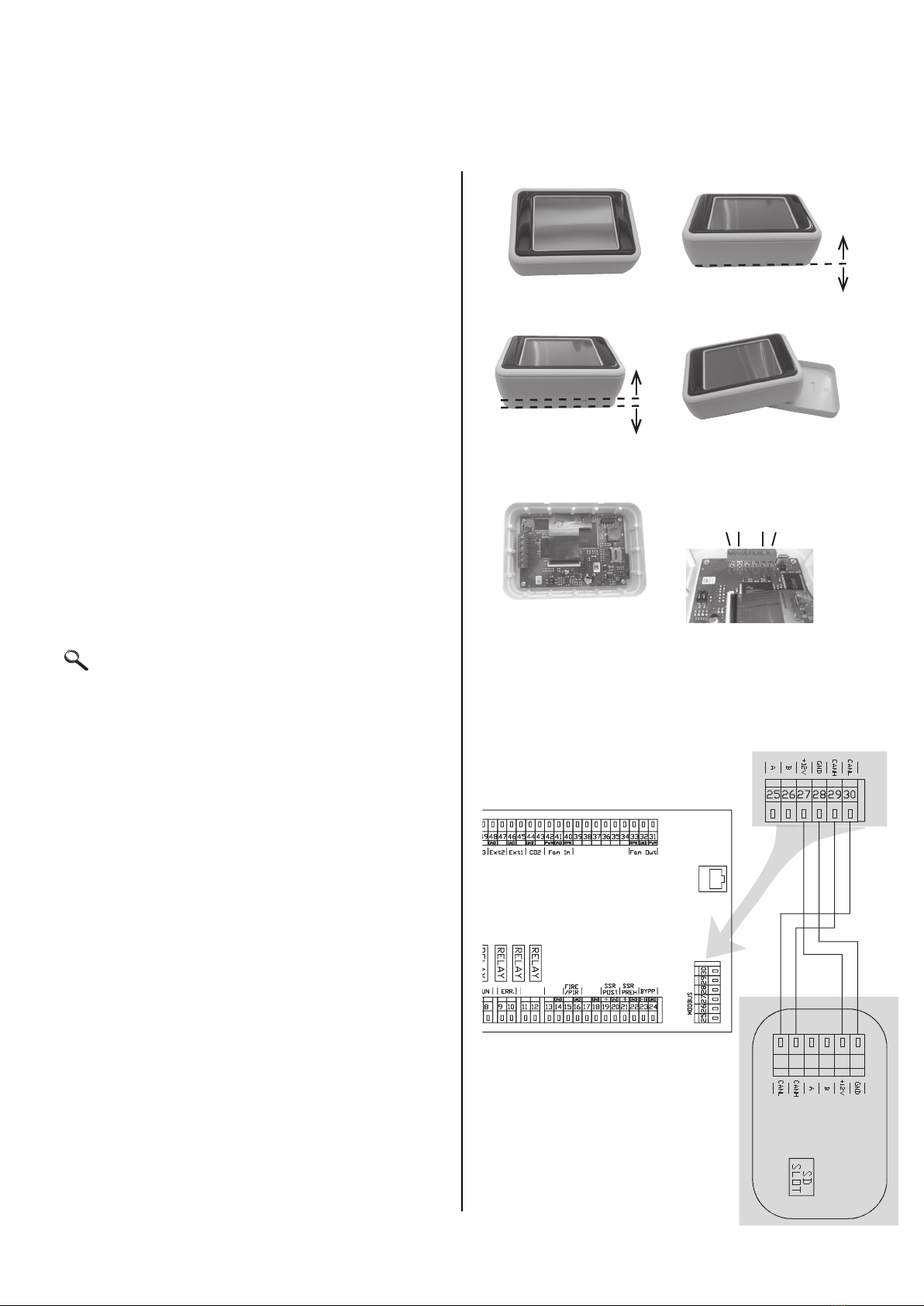
6.5-3 Touchscreen controller
Tostarttheunit,connecttheremotecontroltothe
unitwiththecontrolcable(datacable).
NOTE: Cable not supplied. UTP cable
recommended. The cable length should not exceed
50 m (0.5 mm2)
6.5-2.5 PIR motion sensor
Low voltage switching contact - maximum
possible contact load 12 V, 0.4 A.
CABLE: Cable with two conductors of cross section
min. 0.5 mm2 Maximum length 50 m. The con-
tact is normally open.
When the contact closes, the unit operates
according to the settings in menu 1616.
1.
3.
5.
2.
4.
6.
CANL (30)
CANH (29)
+12 V (27)
GND (28)
PREHEAT
W. PUMP BOOST EXT
Produced in EU
REGULATION REGULATION
The company reserves the right of change without previous announcement. ©2VV, spol. s r.o.
QPN
Your partner in ventilation...
tfofkd=af^do^jp bibhqofp`eb=p`e^iqmi„kb
^ää=ïáêáåÖ=Çá~Öê~ãë=éêçîáÇÉÇ=áå=íÜÉ=íÉÅÜåáÅ~ä=Å~í~äçÖ=
~êÉ=áåÇáÅ~íáîÉ=çåäóK=
tÜÉå= ~ëëÉãÄäáåÖ=íÜÉ=éêçÇìÅíI=
çÄëÉêîÉ=ëíêáÅíäó=íÜÉ=å~ãÉéä~íÉ=ê~íáåÖë=~ë=ïÉää=~ë=
ÇáêÉÅíáçåë=~åÇ=Çá~Öê~ãë=~ÑÑáñÉÇ=ÇáêÉÅíäó=íç= íÜÉ=
éêçÇìÅí=çê=ÉåÅäçëÉÇ=íç=íÜÉ=éêçÇìÅíK
pŽãíäáÅÜÉ=áã= íÉÅÜåáëÅÜÉå=h~í~äçÖ=~åÖÉÑćÜêíÉå=
pÅÜ~äíéäŽåÉ=ëáåÇ=åìê=áåÑçêã~íáîK==_Éá=ÇÉê=jçåí~ÖÉ=
ÇÉë=mêçÇìâíÉë=êáÅÜíÉå=páÉ=ëáÅÜ=~ìëëÅÜäáɡäáÅÜ=å~ÅÜ=
ÇÉå=pÅÜáäÇïÉêíÉå=ìåÇ=pÅÜ~äíÄáäÇÉêåI=ÇáÉ=ÉåíïÉÇÉê=
~ìÑ=ÇÉã= mêçÇìâí=~åÖÉÄê~ÅÜí==çÇÉê=òìã= mêçÇìâí=
ÄÉáÖÉäÉÖí=ëáåÇK
hbv=ql=`lafkd hbkkwbf`ekrkdpp`ei¸ppbi
pbosl=qaJMQJOPMJN
TD-04-230-1
servo drive for controlling the HVAC flaps
TD-04-230-1
Stellantrieb für die Bedienung der lufttech-
nischen Klappen
TD-04-230-1
Type
Тyp
230
Voltage
[V]
Spannung
[В]
2
Standby [W]
Standby
[Вт]
12
Operation
[VA]
Betrieb
[ВA]
4
torque
[Nm]
Drehmoment
[Нм]
90
displacement
time [s]
Verschiebung
Zeit [s]
95°
working angle
max.
Arbeitswinkel
max.
0,5
weight
[kg]
Gewicht
[kg]
Power consumption / Stromverbrauch
Your partner in ventilation...
358
Produced in EU The company reserves the right of change without previous announcement. ©2VV, spol. s r.o.
REGULATION REGULATION
NOTE: Barkell does not supply the above
accessory as standard, it must be ordered
separately.
READ CAREFULLY!
● Thesupplyandthecontrolcableshouldbeasfar
apartfromeachotheraspossible.
● Makesurethatthecablehasbeenproperlyin-
sertedintotheconnector.
● Becarefulnottodamagecableinsulationwhen
xingtheremotecontroltothewallortoother
surface.
● If you do not connect connectors or cables di-
rectly during the unit´s installation, protect
themagainstmechanicaldamageorshortcircuit
byaninsulatingtape.
● Cable connectors must not come into contact
withwaterorotherliquid.
● Parametersettingsaremaintainedthankstothe
batterywiththeservicelifeof3–5years.
20
6.4-4 Connection of the unit to
the BMS control system
The ventilation unit control is normally
equipped with the RS-485 interface.
For connection use a standard communication
cable. Connect the cable to the assigned
MODBUS connectors on the control board.
Connect the other end to the main control unit.
For the protocols details (ModBUS) contact
Barkell.
IMPORTANT NOTICE!
ItispossibletoconnecttheunittotheBMScontrol
systemandtheunitcontrolleratthesametime.
BMScommunicationisonlyavailablethroughthe
RS-485 Modbus interface. Other communication
protocolswillrequireagatewaytranslator.
ForadditionalinformationabouttheMODBUSco-
nnectionpleaseconsultthe THERM-X HRFLMod-
busProtocolmanual.
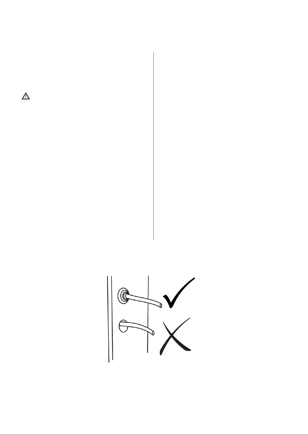
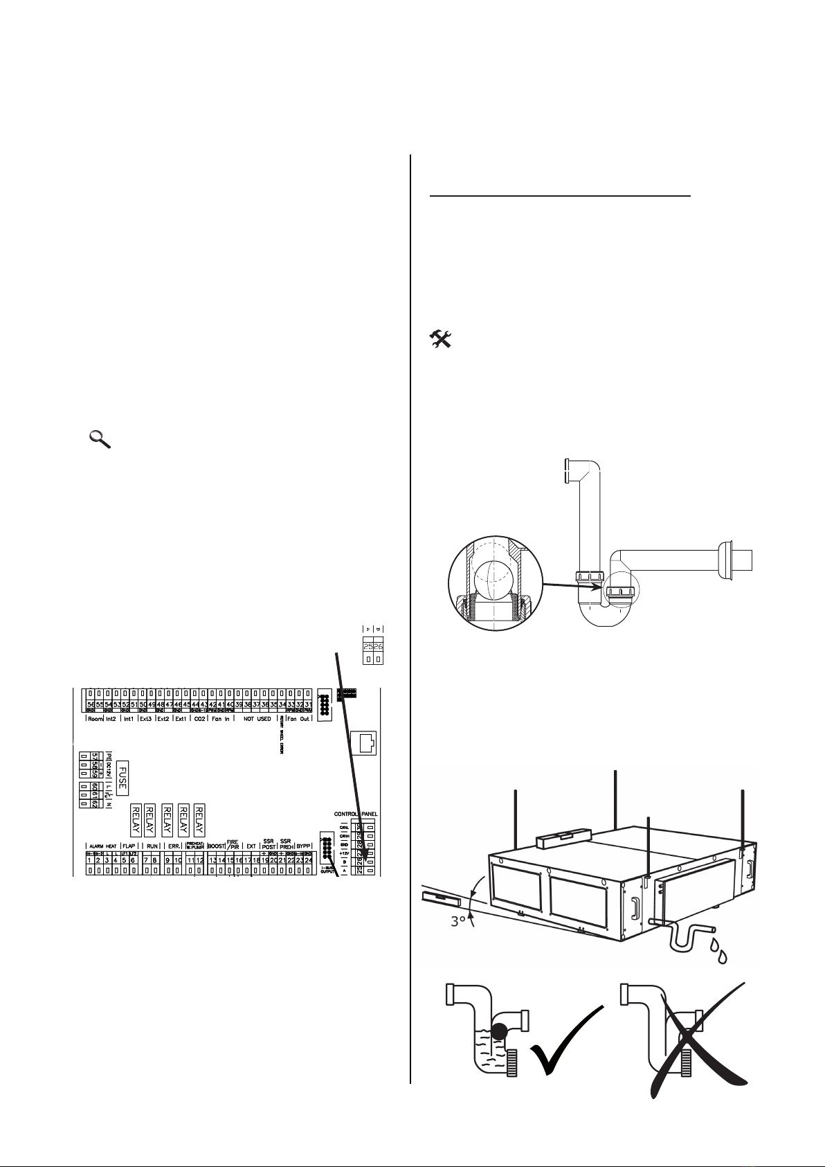
6.5 CONDENSATE DRAIN
CONNECTION
Condensate drain from the unit (either from the
recuperator, the cooling coil (if provided) or both
must be connected to the discharge pipeline.
If the unit has 2 drain connections an additional
trap or pump is required.
Ensure the unit is level or angled slightly towards
the condensate tray outlet to facilitate correct
conden-sate removal from the unit.
YOU WILL NEED
• 1siphon
• PVCdischargepipework
• sealtothedischargepipework
Siphon with a ball
The tube connection on the drain is connected
to the side discharge on the ventilation unit.
Ensure ALL connections are TRAPPED.
6. INSTALLATION
– Makesurethattheunitisinclinedby3°sothat
thecondensatedrainisensured.
Control panel
1
1. 1
5. 1
6.
1
2. 1
7.
1
8.
1
9. 1
10. 1
11. 1
12. 1
13. 1
14. 1
15. 1
16. 1
17.
1
3. 1
4.
1
20. 1
21. 1
22.
1
18. 1
19.
EN RU CZ
1. A (5-6) LF1 - FLAP INLET (output L-open), LF2 - FLAP OUTLET ( output L-open) LF1 ( L-), LF2 - ( L-) LF1 - KLAPKA PŘÍVOD (výstup L-open), LF2 - KLAPKA ODVOD ( výstup L-open)
2. A (7-8) RUN CONTACT (output -NO/NC settable) RUN ( - NO/NC ) RUN KONTACT (výstup -NO/NC nastavitelné)
3. A (9-10) ERROR CONTACT (output NO) ( NO) ERROR KONTACT (výstup NO)
4. A (11-12) PREHEATER WATER PUMP (11 - Lint, 12 - Lout) (11 - Lint,12 - Lout) VODNÍ ČERPADLO PŘEDEHŘEVU (11 - Lint, 12 - Lout)
5. A (13-14) BOOST (input NO) BOOST ( NO) BOOST (vstup NO)
6. A (15-16) FIRE (input NC) FIRE - ( NC) FIRE (vstup NC)
7. A (17-18) EXTERNAL CONTROL ON/OFF (input NC) ON/OFF ( NC) EXTERNÍ OVLÁDÁNÍ ON/OFF (vstup NC)
8. A (18-19) AQS SENSOR 0-10V (input) 0-10 () ČIDLO KVALITY VZDUCHU 0-10V (vstup)
9. B (1-2) WATER PUMP (1 - Lint, 2 - Lout) (1 - Lint, 2 - Lout) VODNÍ ČERPADLO (1 - Lint, 2 - Lout)
10. B (3-4) HEAT PUMP CONTROL settable (output - ON/OFF) ( - ON/OFF) ŘÍZENÍ TEPELNÉHO ČERPADLA nastavitelné (výstup - ON/OFF)
11. B (5-6) ADIABATIC MODULE output - ON/OFF ( - ON/OFF) ADIABATICKÝ MODUL výstup - ON/OFF
12. B (7-8) COOL / HEAT settable (CO = NC/NO - DX = output settable) / (CO = NC/NO - DX = ) CHLAZENÍ / TOPENÍ nastavitelné (CO = NC/NO - DX = výstup nastavitelné)
13. B (9-10) ADIABATIC MODULE ERROR input NO ERROR ( NO) ADIABATICKÝ MODUL ERROR vstup NO
14. B (11-12) HEAT PUMP DEFROST settable (input NC/NO) ( NC/NO) ODMRAŽOVÁNÍ TEPELNÉHO ČERPADLA nastavitelné (vstup NC/NO)
15. B (13-14) HEAT PUMP ERROR settable (input NC/NO) ( NC/NO) CHYBA TEPELNÉHO ČERPADLA nastavitelné (vstup NC/NO)
16. B (15-16) PIR (input NC) PIR ( NC) POHYBOVÉ ČIDLO PIR (vstup NC)
17. B (17-18) CONDENSATE OVERFLOW (input NC) ( NC) ČIDLO PŘETEČENÍ KONDENZÁTU (vstup NC)
18. B (46-47) EXTERNAL TEMPERATURE SENSOR (external postheater - input) ( - ) EXTERNÍ TEPLOTNÍ ČIDLO (externí dohřev - vstup)
19. B (44-45) EXTERNAL TEMPERATURE SENSOR (adiabatic module / recirc. chamber - input) ( / - ) EXTERNÍ TEPLOTNÍ ČIDLO (adiabatický modul / recirkulační komora - input)
20. B (38-39) EXTERNAL PREHEATER (output - Water= 0-10V, electric=PWM) ( - =0-10, =PWM) EXTERNÍ PŘEDEHŘEV (výstup - vodní=0-10V, elektrický=PWM)
21 B (36-37) EXTERNAL POSTHEATER (output - Water= 0-10V, electric=PWM) ( - =0-10, =PWM) EXTERNÍ DOHŘEV (výstup - vodní=0-10V, elektrický=PWM)
22 B (34-35) RECIRCULATION CHAMBER (output 0-10V) ( 0-10) RECIRKULAČNÍ KOMORA (výstup 0-10V)
A
B
MODBUS connection
Table of contents
Popular Fan manuals by other brands

Create
Create WINDLIGHT MINIMAL DC user manual

Casablanca
Casablanca Panama Gallery 55059 Owner's guide and installation manual

RenewAire
RenewAire DN-Series Installation, operation and maintenance manual

Westinghouse
Westinghouse WFF16 user manual

DELTA BREEZ
DELTA BREEZ RAD80L manual

Gallet
Gallet VEN 73T Blizzard instruction manual

Progress Lighting
Progress Lighting AirPro P250062 installation manual

Envirovent
Envirovent energiSava 300 installation guide

CFM
CFM AeroFan Brochure & specs

LEGRAND
LEGRAND HPM RCFTRI12H4WE instruction sheet

Gaggenau
Gaggenau VL 414 712 use and care manual

TemperZone
TemperZone IMDL 40Y Installation & maintenance


