Barker PTD-RGC User manual
PTD-RGC
DELI/MEAT/SEAFOOD
09/16
MULTI-DECK MERCHANDISER
I N S TA L L AT I O N & O P E R AT I O N S M A N U A L
Energy Data & Case Dimensions ......................2-4
General Information ............................................... 5
Installation ..........................................................6-8
Case Connections ............................................ 9-12
Lighting and Power Supplies ......................... 13-14
Pre-Power Checklist ............................................15
Airflow & Defrost ..................................................16
Case Cleaning ................................................ 17-24
Parts Ordering ......................................................25
Appendices
Table of Contents
To ensure proper functionality and optimum performance, it is STRONGLY recommended that Hillphoenix specialty cases be installed/serviced by qualified
technicians who have experience working with commercial refrigerated display merchandisers and storage cabinets. For a list of Hillphoenix-authorized
installation/service contractors, please visit our Web site at www.hillphoenix.com.

ii

R-744 (CO2) NOTICE
For Systems Utilizing R-744 (CO2) Refrigerant
For refrigeration units that utilize R-744 (CO2), pressure relief and pressure-regulating relief valves may need
to be installed based on the system capacity. The valves need to be located such that no stop valve is posi-
tioned between the relief valves and the parts or section of the system being protected.
When de-energizing refrigeration units containing R-744 (CO2), venting of the R-744 (CO2) refrigerant may
occur through the pressure regulating relief valves. These valves are located on the refrigeration system
and not on the case model. If venting does occur, the valve must not be defeated, capped, or altered by any
means.
WARNING: Under no circumstances should any component be replaced or added without consulting
Hillphoenix Field Service Engineering. Utilizing improper components may result in serious injury to
persons or damage to the system.
LIABILITY NOTICE
For Cases with Shelf Lighting Systems
Hillphoenix does NOT design any of its shelf lighting systems or any of its display cases with shelf lighting
systems for direct or indirect exposure to water or other liquids. The use of a misting system or water hose
on a display case with a shelf lighting system, resulting in the direct or indirect exposure of the lighting
system to water, can lead to a number of serious issues (including, without limitation, electrical failures,
!re, electric shock, and mold) in turn resulting in personal injury, death, sickness, and/or serious property
damage (including, without limitation, to the display itself, to the location where the display is situated
[e.g., store] and to any surrounding property). DO NOT use misting systems, water hoses or other devices
that spray liquids in Hillphoenix display cases with lighted shelves.
If a misting system or water hose is installed or used on a display case with a shelf lighting system, then
Hillphoenix shall not be subject to any obligations or liabilities (whether arising out of breach of contract,
warranty, tort [including negligence], strict liability or other theories of law) directly or indirectly resulting
from, arising out of or related to such installation or use, including, without limitation, any personal injury,
death or property damage resulting from an electrical failure, !re, electric shock, or mold.
P079211M, REVO
iii

Important
D A N G E R
•
Indicates an immediate threat of death or seri-
ous injury if all instructions are not followed
carefully.
At Hillphoenix®, the safety of our customers and employees, as well as the ongo-
ing performance of our products, are top priorities. To that end, we include impor-
tant warning messages in all Hillphoenix installation and
operations handbooks, accompanied by an alert symbol paired with the word
"DANGER", "WARNING", or "CAUTION".
All warning messages will inform you of the potential hazard; how to reduce the
risk of case damage, personal injury or death; and what may happen if the in-
structions are not properly followed.
W A R N I N G
Indicates a potential threat of death or serious
injury if all instructions are not followed care-
fully.
•
C A U T I O N
Indicates that failure to properly follow instruc-
tions may result in case damage.
•
iv

Revision History
• new manual format_12/13
• energy data_01/14
• energy data_03/14
• endviews_09/14
• support diagram and parts page_02/15
• warranty_04/16
• energy data_09/16
v

ENERGY DATA
Numbers are based on standard case sizes. Consult engineering.
All measurements are taken per ARI 1200 - 2002 specifications.
Engineered for stores with ambient conditions not to exceed 75o and 55% relative humidity.
Due to engineering improvements specifications may change without notice.
PTD-RGC COOLGENIX
Electrical Data
1 NOTE: “- - -” indicates data not applicable.
2 RRS - Refrigerated Rear Storage.
3,4 Listed BTUH indicates unlighted shelves. Add the following for lighted shelves:
4’ Fluorescent: 80 BTUH
3’ Fluorescent: 60 BTUH
4’ Shelf LED: 36 BTUH
4’ Canopy LED: 72 BTUH
3’ Shelf LED: 27 BTUH
3’ Hi-Output LED: 54 BTUH
5 Average discharge air velocity at peak of defrost.
6,7 Time-off duration for defrost with no termination control.
Model
Fans
per
Case
High Ef!ciency
Fans
Anti-Condensate
Fans
Drain
Heaters
Optional Defrost
Heaters
RRS2
Fans
per
Case
Unit Cooler Fans
120 Volts 120 Volts 120 Volts 208 Volts 120 Volts
Amps Watts Amps Watts Amps Watts Amps Watts Amps Watts
PTD-RGC (BASE) 6’ 2 0.6 72 - - -1- - - - - - - - - - - - - - - - - - - - - - - -
8’ 3 0.9 108 - - - - - - - - - - - - - - - - - - - - - - - - - - -
10’ 4 1.2 144 - - - - - - - - - - - - - - - - - - - - - - - - - - -
12’ 4 1.2 144 - - - - - - - - - - - - - - - - - - - - - - - - - - -
Defrost Controls
Model
Defrosts
per Day
Run-Off
Time (min)
Electric Defrost Timed-Off Defrost Hot Gas Defrost
Fail-Safe
(min)
Termination
Temp (oF)
Fail-Safe
(min)
Termination
Temp (oF)
Fail-Safe
(min)
Termination
Temp (oF)
PTD-RGC (BASE) DX 4 - - - - - - - - - 65/636 42 - - - - - -
RRS 4 - - - - - - - - - 65/736 42 - - - - - -
Model
Lights
per
Row
Light
Length
(ft)
Fluorescent Lighting
(Per Light Row)
Clearvoyant LED Lighting
(Per Light Row)
Standard Power
(Cornice or Shelf)
High Power
(Cornice)
120 Volts 120 Volts 120 Volts
Amps Watts
Maximum
Allowable
Rows Amps Watts
Maximum
Allowable
Rows Amps Watts
Maximum
Allowable
Rows
PTD-RGC (BASE) 6’ 2 3 0.34 40.8 - - - 0.14 16.8 - - - 0.24 28.8 - - -
8’ 2 4 0.47 56.4 - - - 0.20 24.0 - - - 0.36 43.2 - - -
10’ 2 5 0.61 73.2 - - - 0.24 28.8 - - - 0.44 52.8 - - -
12’ 3 4 0.69 82.8 - - - 0.30 36.0 - - - 0.54 64.8 - - -
Lighting Data
Guidelines & Control Settings (DX)
Model
Conventional
3BTUH/ft
Parallel
4BTUH/ft
Superheat
Set Point @ Bulb
(oF)
Evaporator
(oF)
Discharge
Air
(oF)
Discharge Air5
Velocity
(FPM)
PTD-RGC (BASE) DX 485 445 6-8 26 29 250
RRS 109 100 10 26 29 200
2

ENERGY DATA
PTD-RGC COOLGENIX
Numbers are based on standard case sizes. Consult engineering.
All measurements are taken per ARI 1200 - 2002 specifications.
Engineered for stores with ambient conditions not to exceed 75o and 55% relative humidity.
Due to engineering improvements specifications may change without notice.
Electrical Data
1 NOTE: “- - -” indicates data not applicable.
2 Semi Self-Contained is NOT available in a 4’ case.
* Listed data is based on the factory recommended default fresh meat temperature settings.
* Shelves are not recommended for fresh meat applications.
Model
Defrosts
per Day
Run-Off
Time (min)
Electric Defrost Timed-Off Defrost Hot Gas Defrost
Fail-Safe
(min)
Termination
Temp (oF)
Fail-Safe
(min)
Termination
Temp (oF)
Fail-Safe
(min)
Termination
Temp (oF)
PTD-RGC (DOME) 1 5 - - - - - - 60 45 - - - - - -
Guidelines & Control Settings (Remote Secondary/Semi-Self Contained2)
Defrost Controls
Model
Fans
per
Case
High Ef!ciency
Fans
Anti-Condensate
Fans
Drain
Heaters
Optional Defrost
Heaters
120 Volts 120 Volts 120 Volts 208 Volts
Amps Watts Amps Watts Amps Watts Amps Watts
PTD-RGC (DOME) 4’ - - -1- - - - - - - - - - - - - - - - - - - - - - - -
6’ - - - - - - - - - - - - - - - - - - - - - - - - - - -
8’ - - - - - - - - - - - - - - - - - - - - - - - - - - -
10’ - - - - - - - - - - - - - - - - - - - - - - - - - - -
12’ - - - - - - - - - - - - - - - - - - - - - - - - - - -
Model
Lights
per
Row
Light
Length
(ft)
Fluorescent
Lighting
(Per Light Row)
Clearvoyant LED Lighting
(Per Light Row)
Standard Power
(Cornice or Shelf)
High Power
(Cornice)
120 Volts 120 Volts 120 Volts
Amps Watts
Maximum
Allowable
Rows Amps Watts
Maximum
Allowable
Rows Amps Watts
Maximum
Allowable
Rows
PTD-RGC (DOME) 4’ - - - - - - - - -
6’ 2 3 0.37 44.0 - - - 0.14 16.6 - - - 0.24 29.8 - - -
8’ 2 4 0.47 56.0 - - - 0.20 23.8 - - - 0.36 43.0 - - -
10’ 3 3 0.71 85.0 - - - 0.21 25.2 - - - 0.40 48.0 - - -
12’ 3 4 0.71 85.0 - - - 0.30 35.7 - - - 0.54 64.5 - - -
Lighting Data
Cut-In/Cut-Out
Model
Cut-In
Temp (oF)
Cut-Out
Temp (oF)
PTD-RGC (DOME) Pans 33 29
Top Coil 36 31
Model
Conventional
BTUH/ft
Parallel
BTUH/ft
Glycol
Supply Temp.
(oF)
DX SST
Chiller
Temp. (oF)
Glycol
Flow Rate
GPM/ft
Glycol
Charge
GAL/ft
Glycol
Max. Working
Pressure (PSIG)
Max. Static
Pressure
(PSIG)
PTD-RGC (DOME) 250 240 26 20 0.25 0.20 50 - - -
3

PTD-RGC COOLGENIX
CASE DIMENSIONS
POWER SUPPLY
2 1/16 in
[5.2 cm]
18 in
[45.7 cm]
51 in
[129.6 cm]
6 in
[15.2 cm]
12 in
[30.5 cm]
1 in
[2.5 cm]
1 in
[2.5 cm]
15" x 11" MECHANICAL ACCESS
FOR ELECT. ,REFRIG. ,AND DRAIN CONNECTIONS TOEKICK
42 in
[106.7 cm]
TOEKICK
72 1/2 in [184.2 cm] {6’ case}
L
C
FRONT OF CASE
26 in
[66.0 cm]
96 1/2 in [245.1 cm] {8’ case}
120 1/2 in[306.1 cm] {10’case}
144 1/2 in[367.0 cm] {12’ case}
ELECTRICAL RACEWAY
LOWER REAR STORAGE
WITH DOORS
6 1/4 in
[15.9 cm]
42 in
[106.7 cm]
51 in
[129.5 cm]
1 1/2 in
[3.7 cm]
34 5/16 in
[87.2 cm]
20 3/8 in
[51.7 cm] 9 1/4 in
[23.5 cm]
13 7/8 in
[35.2 cm]
22 3/4 in
[57.8 cm]
14 in
[35.6 cm]
LOAD LIMIT LINE
16 3/4 in
[42.5 cm]
14 5/8 in
[37.2 cm]
REFLECTIVE
REAR LOAD DOORS
16 13/16 in
[42.7 cm]
14 3/16 in
[36.0 cm]
14 13/16 in
[37.7 cm]
[123.2 cm] {4’ case}48 1/2 in
4

Hillphoenix Barker Specialty Products
703 Franklin Street, PO Box 478
Keosauqua, IA 52565
Tel: (319) 293-3777/Fax: (319) 293-3776
Web site: www.hillphoenix.com
GENERAL INFORMATION
Thank you for choosing Hillphoenix for your food merchandising needs. This handbook contains important technical information
and will assist you with the installation and operation of your new Hillphoenix specialty cases. By closely following the instruc-
tions, you can expect peak performance; attractive fit and finish; and long case life.
We are always interested in your suggestions for improvements (e.g. case design, technical documents, etc.). Please feel free to
contact our Marketing Services group at the number listed below. Thank you for choosing Hillphoenix, and we wish you the very
best in outstanding food merchandising.
CASE DESCRIPTION
This manual specifically covers the PTD-RGC beverage, deli,
meat and seafood application, self-service open multi-deck
merchandiser with service dome.
STORE CONDITIONS
Hillphoenix cases are designed to operate in an air-condi-
tioned store that maintains a 75°F (24°C) store temperature
and 55% (max) relative humidity (ASHRAE conditions). Case
operation will be adversely affected by exposure to excessively
high ambient temperatures and/or humidity.
REFRIGERATION SYSTEM OPERATION
Air-cooled condensing units require adequate ventilation for
efficient performance. Machine-room temperatures must be
maintained at a minimum of 65°F in winter and a maximum
of 95°F in summer. Minimum condensing temperatures
should be no less than 70°F.
SHIPPING CASES
Transportation companies assume all liability from the time a
shipment is received by them until the time it is delivered to
the consumer. Our liability ceases at the time of shipment.
RECEIVING CASES
Examine fixtures carefully and in the event of shipping dam-
age and/or shortages, please contact the Service Parts
Department at the number listed below.
CASE DAMAGE
Claims for obvious damage must be 1) noted on either the
freight bill or the express receipt and 2) signed by the carrier's
agent; otherwise, the carrier may refuse the claim. If damage
becomes apparent after the equipment is unpacked, retain all
packing materials and submit a written request to the carrier
for inspection within 14 days of receipt of the equipment.
Failure to follow this procedure will result in refusal by the
carrier to honor any claims with a consequent loss to the
consumer.
If a UPS shipment has been damaged, retain the damaged
material, the carton and notify us at once. We will file a
claim.
LOST/MISSING ITEMS
Equipment has been carefully inspected to insure the highest
level of quality. Any claim for lost/missing items must be
made to Hillphoenix within 48 hours of receipt of the equip-
ment. When making a claim please use the number listed
below.
SERVICE & TECHNICAL SUPPORT
For service or technical questions regarding specialty cases,
please contact our Specialty Products Division Service
Department at 1-319-293-3777. For questions regarding our
refrigeration systems or electrical distribution centers, please
contact our Systems Division Customer Service Department at
1-770-388-0706.
CONTACTING THE FACTORY
If you need to contact Hill PHOENIX regarding a specific fix-
ture, be certain that you have both the case model number
and serial number (this information can be found on the data
tag, located on the top-left interior of the case). When you
have this information, call the number below and ask for a
Service Parts Representative.
PRESSURE TESTING
Standard practice for pressure testing secondary systems is to
pressurize the system to 100 psi. This case must be limited to
70 psi or damage to the deck pans and micro-channel coolers
may occur. If the cases are piped to racks not supplied by
Hillphoenix ensure that a properly sized pressure regulator is
installed upstream of the cases.
GYLCOL
Glycols used in Hillphoenix secondary-coolant cases should
NEVER be mixed between different manufacturers. Each
manufacturer may have different additives or inhibitors that will
congeal when mixed with other manufacturers materials. For
more detailed information, please refer to the Secondary
Nature manual located on our web site.
5
CASE INSTALLATION
FLOOR PREP
1. Ask the general contractor if your current copy of the build-
ing dimensions are the most recently issued. Also, ask for
the points of reference from which you should take dimen-
sions to locate the cases.
2. Using chalk lines or a laser transit, mark the !oor where
the cases are to be located for the entire lineup. The lines
should coincide with the outside edges of the case feet.
3. Move case as close as possible to its permanent location.
Remove all crating and shipping braces above the ship-
ping pallet. Loosen the plastic dust cover from the pallet,
but leave cover over the case to protect it while removing
the case from the pallet. Carefullly, lift case up and off the
pallet. Remove dust cover. Istallation hardware ships in a
marked packet located inside the case.
4. Leveling is necessary to ensure proper operation of the
refrigeration system and drainage of the condensate.
Locate the highest point on the positioning lines as a ref-
erence for determining the proper height of the shim-pack
levelers. A laser transit is recommended for precision and
requires just one person. Level adjustable feet by twisting,
if appliacble, or shim as necessary under vertical supports
as this will help ensure that the case is not settling over
time.
5. Locate horizontal support (Fig. 1) positions along the chalk
line. Spot properly leveled shim packs at each support
location.
LOCATION
This refrigerated display case has been designed for displaying
and storing perishable food product. It is engineered for air-
conditioned stores with a maximum ambient of 75°F and 55%
relative humidity.
When selecting the location for placement of this case, avoid
the following conditions:
Excessive Air Movement
1. Doors
2. Air-conditioned vents
3. Other air sources
Excessive Heat
1. Windows
2. Sun
3. Flood lamps 8 feet or less from the product
4. Other heat sources
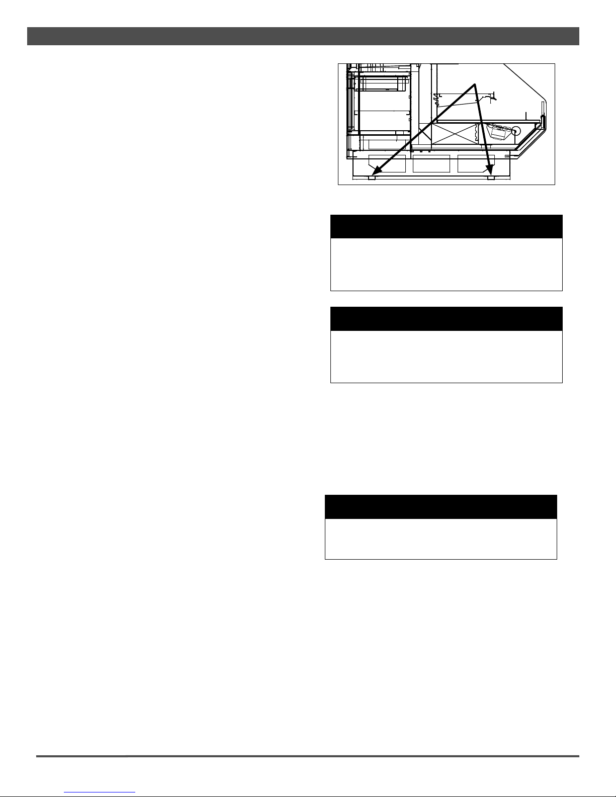
C A U T I O N
Locate the horizontal supports under unit before
removing from pallet. Failure to do so will dam-
age the "nished metal if correct lift points are
not identi"ed prior to removal.
•
C A U T I O N
These cases are not designed for excessive
external weight. Do not walk on top or inside
of cases. Doing so may result in case damage
and/or personal injury.
•
Fig. 1 Horizontal supports
SUPPORTS
LINE-UP & INSTALLATION
Single Case
1. Move the case into position. Using a “J” bar, raise the end
of the case (under cross support), and lower the horizontal
support on to the shim packs. Repeat on the other end of
the case.
2. Once the case is properly placed on the shim packs,
check the vertical plumb of the case by placing a bubble
level on the rear wall. Add/remove shim packs as needed.
For the horizontal level, repeat this process after placing
the bubble level on the front sill.
3. Install the bumper, if applicable, into pre-attached bumper
track and snap into place.
4. After suf"cient time has passed to allow for bumper
shrinkage, cut away the excess bumper for "nal "t and "n-
ish. Be certain to use an appropriate cutting tool (tubing-
or PVC-cutter) to ensure a smooth cut.
5. Install case shelves and reconnect lights. Be aware that
W A R N I N G
Be certain that your hands and feet are out of
the way before lowering the case. Failure to do
so may result in serious injury.
•
6
CASE INSTALLATION
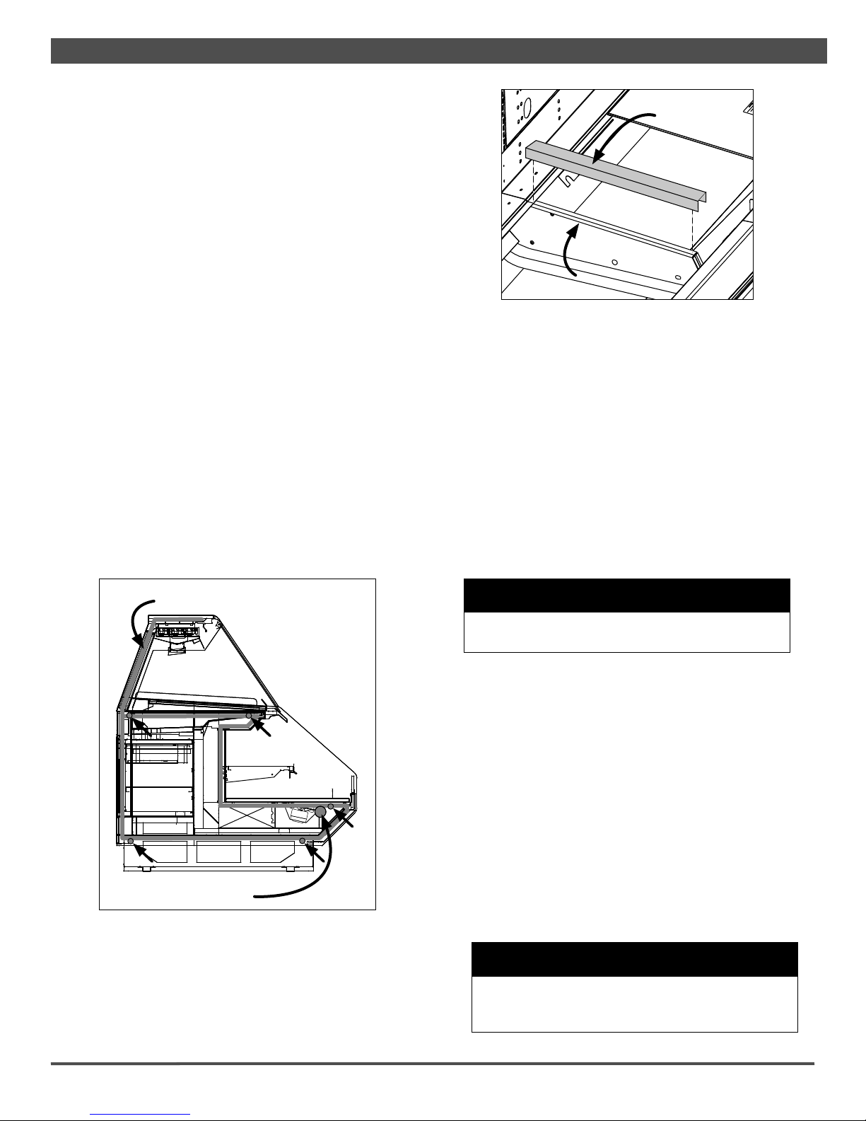
Fig. 2 Sealant, piping, and bolt locations
Multi-Case
1. Remove any shelves (discard the shelf clips) and/or loose
items from the cases that may interfere with case joining.
Keep all loose items as they will be used later in the instal-
lation process.
2. Follow the single-case installation instructions for the •rst
case,excluding #6, then position the next case in the line-
up approximately 3’ away.
3. Apply the foam tape (supplied) to the end breakers of the
•rst case. After this is set apply the sealant to the end of
the case. From the opposite end, push the second case to
a position that is approximately 6" from the •rst case, then
position case on the shim packs.
4. Push the cases tightly together, then lightly bolt them
together through the holes provided (Fig.2). Tighten all the
joining bolts until all margins are equal. Be careful not to
over tighten.
5. Install PVC •tting between cases with case to case piping
(Fig. 2). It is very important for line ups designed with
holes in the pipe chase and equipped with PVC •ttings to
seal between the joints and protect piping.
6. Apply case-to-case watershed (supplied) over the end
frame seam (Fig. 3). The watershed prevents water from
settling in the case joint.
7. Repeat steps 3-6 of this sequence for all remaining cases.
Be certain to properly level all cases.
Fig. 3 Sealing the end frame
WATERSHED
END FRAME
C A U T I O N
Installation of 3rd-party materials may result in
diminished case performance.
•
COOLGENIX PANS
Deck Pans
1. The Coolgenix deck pans are the main source of cooling.
2. All products placed into the Coolgenix case must be at the
appropriate temperature before placing into the case.
3. Warm product should not be placed inside a case.
differing shelf con•gurations will affect energy consump-
tion and case performance.
6. Install toekick back onto the base of case.
8. Properly align the front panels as needed, then install, if
applicable, front panel trim (supplied).
9. Install the bumper into pre-attached bumper track and
snap into place.
10. After suf•cient time has passed to allow for bumper
shrinkage, cut away the excess bumper for •nal •t and •n-
ish. Be certain to use an appropriate cutting tool (tubing-
or PVC-cutter) to ensure a smooth cut.
11. Install case shelves and reconnect lights. Be aware that
differing shelf con•gurations will affect energy consump-
tion and case performance.
12. Install toekick back onto the base of case.
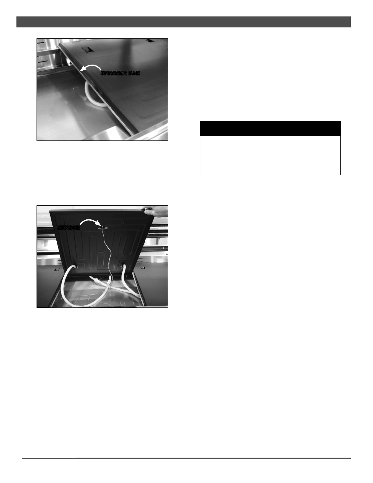
Spanner Bars
1. Spanner bars (Fig. 4) are a very important support for
Coolgenix pans.
2. To prevent warping spanner bars MUST be used under
Coolgenix pans.
CAUTION
Support spanner bars must be under Coolgenix
pans to prevent warping of pans. Failure to use
these bars will void warranty on pans.
•
PIPE LOCATION
SEALANT
7
CASE INSTALLATION
Pan Sensors
1. The center deck pan and shelving (if applicable) have a
pan sensor connected to the underside (Fig. 5). Not every
pan will have this sensor. Check the underside of each
pan to see which pan(s) have this sensor.
Fig. 5 Coolgenix pan sensor
Displaying
1. All display trays must lie !at on the pans without feet.
2. Any space between the display trays and pans will cause
early product deterioration due to insuf"cient contact with
the pans.
3. Making contact with the deck pans and display tray is vital
for keeping product temperature.
4. The use of foam, riders, any type of shelf liners, Dri-Loc
pads or display dividers that raise trays off the deck pans
should not be used.
Loading
1. When loading a case the product should be loaded
through the rear load door opening.
2. The rear doors should never be removed while merchan-
dising. This is recommended to ensure optimum case
operation and to prevent contamination of rear door
surfaces.
3. The front lift glass should only be lifted when cleaning the
inside of the glass.
C A U T I O N
Coolgenix pans are not designed to be used with
ice in direct contact. Doing so may cause damage
to the Coolgenix pans. Ice can only be used as
an accent lightly sprinkled on product, or with a
polycarbonate ice tray.
•
SENSOR
2. The pan sensor monitors and controls the product temper-
ature. It is very important that the sensor not be discon-
nected from the pan while the cases are in use.
3. The pans will not function as designed if the pan sensor is
not attached to the center deck pan.
Fig. 4 Spanner bar
SPANNER BAR
8

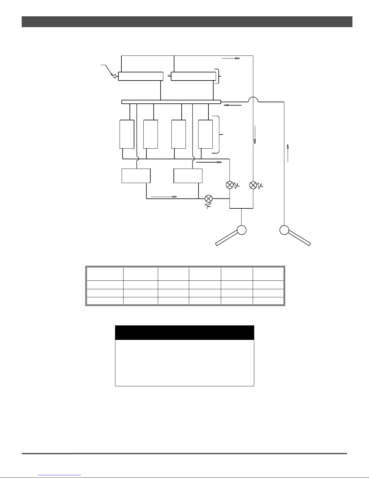
SEMI-SELF-CONTAINED
Hillphoenix SSC (Semi-Self-Contained) cases utilize an open-
loop secondary system, supplying independent circuits to the
Coolgenix pans, shelves and the gravity top coils. All circuits
return to a common reservoir tank that is maintained at atmo-
spheric pressure. All cases are tested and shipped with a 35%
mixture of Dowfrost propyleneglycol.
Charging the refrigeration system is imperative to maximizing
case performance by ensuring that excess air is eliminated
from the system - excessive air in the system can reduce
the heat transfer capacity and even block the •ow to one or
more of the heat transfer components (e.g. Coolgenix Pans or
section of the top coils). Also, charging the system •oods the
pump, which helps prevent damage caused by cavitation.
Starting a Newly Delivered SSC Case
Unless otherwise speci!ed, all SSC cases are charged and
tested at the factory. Much of the •uid is drained out of the
reservoir to prevent spillage during shipment and handling.
Before starting the case, the DX (direct expansion) side of the
chiller must be connected to the appropriate refrigerant lines
and the power connected to the case.
Starting the case consists of topping-off the reservoir tank and
ensuring that all hand-valves are open, then supplying power
by turning the main control and pump switches to their respec-
tive "ON" positions. This requires access to the chiller and the
electrical box.
For cases with pedestals, the chiller is located in the right-
hand pedestal while the electrical box is in the left-hand ped-
estal. The !lling tube can be accessed by removing only the
rear of the right hand pedestal. Cases that are fully skirted
require the removal of the lower back panel to access the
chiller and the electrical box.
There are 2 indicator lamps - one red, one blue - located in
the upper back panel. The red lamp indicates that the •uid
level in the reservoir is low and should be topped-off. The blue
lamp indicates that the reservoir is full and that no more glycol
should be added to avoid spills. If neither lamp is lit, the •uid
level is in the operating range. To top-off the reservoir, remove
the !lling tube from its holding position and extend it to insure
that there are no kinks or obstructions. Remove the charging
cap and pour in propyleneglycol (use only 35% Dowfrost) until
the blue lamp lights, indicating that the reservoir tank is full.
Replace the charging cap and return the hose to its holding
position.
Recharging a Drained System
There may be circumstances when the glycol system needs to
be drained, •ushed, and recharged - usually due to contami-
nants being added to the approved propylene glycol. Charging
and air purging should be performed with the hand-valve on
the DX-side of the chiller closed.
Field charging the chiller system requires "bumping the pump".
The pump is capable of emptying the reservoir faster than •uid
can be poured into it. When the system is empty, the reservoir
must be !lled until the blue light is illuminated. The pump
should then be "bumped" on-and-off using the pump switch
until the red light comes on. The reservoir has to be re!lled
and the process repeated until the red light no longer comes
on. The pump can then be left on.
Each circuit in the system may be cycled by adjusting the set-
point values above "AMBIENT" to stop •ow and below "FLUID
TEMPERATURE" to force •ow. This will help force any en-
trapped air out of the pans and top coils. The •ow through the
system is never perfectly silent; however if an obvious gurgling
sound is heard in any of the pans or at the outlet of a top coil,
this indicates air movement at that location.
Increased •ow can be forced by restricting the •ow to the other
components in the circuit. For pans with quick connects, this
can be done by disconnecting one of the hoses to the non-
problem pans. For pans without quick connects, the •ow can
be restricted by pinching the feed hoses on the non-problem
components. Do not use any kind of clamp that could cut or
tear the hoses.
There are also Schrader !ttings in the return headers of each
of the top coils. Entrapped air may be bled off by depressing
the core of the !tting or removing it until a solid •uid stream
is present. While purging air, be certain to make note of the
red indicator lamp - do not allow the reservoir to empty. Once
the majority of the air is purged and the case is performing
acceptably, top-off the reservoir until the blue lamp is on, open
the DX-side hand valve, and close up the case. Any incidental
air in the system will be removed during the normal operation
of the case.
C A U T I O N
Dowfrost propylene glycol is used for pres-
sure testing and system charging. If another
approved glycol is utilized, the case MUST be
•ushed with pure water to remove any residual
glycol before !lling. Failure to do so will void the
manufacturer warrarnty. Never mix manufactur-
ers of glycol.
•
CASE CONNECTIONS
REFRIGERATION
Refrigeration connections will be made through the refrigera-
tion stub up location on the customer left side of the case.
Refrigeration lines may be headed together for all cases in a
line-up, if necessary, by lines through the access holes with a
high grade silicon to prevent recirculation. All lines must be
9

CASE CONNECTIONS
ELECTRICAL
Electrical hookups are made through the power supply box
that can be accessed by removing the back panel.
For case-to-case wiring, run conduit between the power supply
boxes or run wiring through the raceway. When connecting to
the power supply on the case, •eld wiring should exit box from
the side furthest away from case wiring to allow more room in-
side for wiring connections. Always check the data tag located
on left end exterior panel or top interior of the case. The case
must be grounded. For more detailed electrical wiring infor-
mation, see Appendices A1-A4.
C A U T I O N
Be certain that all plumbing connections are
compliant with local codes.
•
C A U T I O N
Be certain that all electrical connections are
compliant with local codes.
•
C A U T I O N
Be sure to remove all styrafoam shipping blocks
from piping and refrigerant lines. Failure to do
so may result in case damage.
•
Fig. 6 "P" trap / drain outlet
PLUMBING
The drain outlet or “P” trap (Fig. 6) is shipped loose with the
case and made from a 1 1/2” PVC pipe. Care should be given
to ensure that all connections are water-tight and sealed with
the appropriate PVC or ABS cement.
Drain lines can be run left or right of the tee with the proper
pitch to satisfy local drainage requirements. When connecting
the PVC to the existing !oor drains be sure to provide as much
downhill slope as possible and avoid long runs of drain lines.
Do not install condensate drains in contact with non-insulated
suction lines in order to prevent condensate from freezing.
Install the 1 1/2" PVC trap, which is provided with the case. All
drains must be trapped.
Before operating the case, be certain to remove the styrafoam
shipping block that protects the plumbing lines during ship-
ping.
C A U T I O N
If any brazing is necessary, place wet rags
around the area to avoid tank damage.
•
C A U T I O N
Be certain that all piping connections are com-
pliant with local codes.
•
C A U T I O N
If the shelves are removed from the case or other-
wise not utilized, the shelf setpoint (SAA) must be
raised to 90 oF to prevent the pump from running
when only the shelves are calling for refrigeration.
Failure to do so could result in early pump failure.
•
correctly sized. See diagram on page 12 for access locations.
If it becomes necessary to penetrate the case bottom for any
reason, make certain it is sealed afterward with canned-foam
sealant and white RTV.
10
C A U T I O N
Dowfrost propylene glycol is used for pressure
testing and system charging. If another approved
glycol is utilized, the case MUST be •ushed with
pure water to remove any residual glycol before
•lling. Failure to do so will void the manufacturer
warrarnty. Never mix manufacturers of glycol.
•
Coil Return Header
Schrader Valve
On Each Coil Return
Top Coils
Refer to
the table
for the
correct
number of
coils
Supply
Header
Coolgenix
Pan
Coolgenix
Pan
Coolgenix
Pan
Coolgenix
Pan
Refer to
the table
for the
correct
number of
pans
Pan
Solenoid
(SV-2)
Top Coil
Solenoid
(SV-1)
Pan Return Header
Hand Valve Hand Valve
Coolgenix
Shelves
Coolgenix
Shelves
(optional) (optional)
Shelf
Solenoid
(SV-4)
Shelf Return Header
CASE CONNECTIONS
Case Length
Number of
Regular Pans
Number of
LH Pans
Number of
RH Pans
Number of
Coils
Number of
Shelves
6' 3 N/A N/A 1 1
8' 4 N/A N/A 2 2
12' 6 N/A N/A 3 3
11
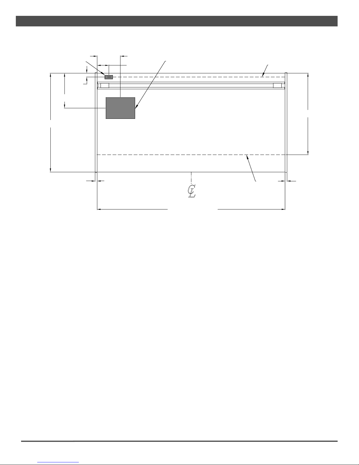
MECHANICAL ACCESS LOCATIONS
CASE CONNECTIONS
POWER SUPPLY
2 1/16 in
[5.2 cm]
18 in
[45.7 cm]
51 in
[129.6 cm]
6 in
[15.2 cm]
12 in
[30.5 cm]
1 in
[2.5 cm]
1 in
[2.5 cm]
15" x 11" MECHANICAL ACCESS
FOR ELECT. ,REFRIG. ,AND DRAIN CONNECTIONS TOEKICK
42 in
[106.7 cm]
TOEKICK
L
C
FRONT OF CASE
72 1/2 in [184.2 cm] {6’ case}
96 1/2 in [245.1 cm] {8’ case}
120 1/2 in[306.1 cm] {10’case}
144 1/2 in[367.0 cm] {12’ case}
[123.2 cm] {4’ case}48 1/2 in
12

LIGHTING & POWER SUPPLIES
GENERAL LIGHTING INFORMATION
Hillphoenix cases are equipped with either T-8 lights or LED
luminaires and feature specially designed light reflectors in the
cornice to improve the illumination of products. Depending on
case configuration, T-8 electronic ballasts or LED power sup-
plies operate both the cornice and shelf lights and are located
above the cornice reflectors.
The lighting system in the electrical raceway has an ON/OFF
switch located at the back exterior of the case. Once cases
have been properly positioned in the store and an electrician
has connected the lighting circuit, the lights may be turned on
to verify that they are connected and functioning properly.
To ensure peak performance, it is advisable to run the lighting
systems only when the store climate control is on and case
refrigeration is started. NOTE: it is highly recommended that
the ambient store temperature not exceed 80°F.
D A N G E R
▲
SHOCK HAZARD
Always disconnect power to case when cleaning,
servicing or con!guring components of the light-
ing system. Failure to do so may result in serious
injury or death.
Fig. 7 T-8 light power cords
W A R N I N G
▲
Using improper DC power supplies may damage
the luminaires, resulting in sub-standard opera-
tion and increased chances of safety issues/
injury.
W A R N I N G
▲
Never replace a 24V DC power supply with a T8
or T5 ballast of any kind" Ballasts use alternat-
ing current (AC) instead of direct current (DC)
and operate at a much higher voltage than is
used by this LED system. Doing so will damage
the LED system and increases the chance of
safety issues/injury.
BALLAST/POWER SUPPLY ACCESS
To gain access to the ballasts or power supplies remove the
panel located above the rear toe kick (Fig. 10).
Fig. 8 T-8 cap and lamp holder
LAMP HOLDER
CAP
Fig. 9 Positive engagement
SHELF LUMINAIRES
1. Unplug T-8 lamp power cords located at the inside-back of
the case below the lamp being replaced (Fig.7).
2. Carefully seperate the cap from the lamp holder on both
ends of the T-8 lamp (Fig. 8). Simultaneously pull down at
both ends of the old T-8 lamp to remove.
3. Push and snap the new T-8 lamp into place on the lamp
holder. When the T-8 is properly seated, the lamp button
- which secures the T-8 to the lamp holder - will be clearly
visible through the lamp button hole. The cap should be
pushed all the way down (Fig. 9) for positive engagement
indicator.
13

LIGHTING & POWER SUPPLIES
REPLACING LED LIGHTS
Once store power is connected and the light circuit is ener-
gized, the Clearvoyant LED system should operate without
the need for any signi•cant maintenance for several years.
Should a power supply need to be removed and/or replaced,
turn off the power to the case before proceeding. Be certain
to replace the power supply with genuine Hillphoenix parts or
a comparable UL-listed Class-2 rated regulated 24V DC power
supply with 100W output capacity.
SHELF LUMINAIRES
Removing shelf luminaires:
1. Unplug the luminaire.
2. Pinching the latching clips inward at the ends of the lumi-
naire, rotate luminaire up at each end until hooks are free,
then remove.
Re-installing shelf luminaires:
1. Place hook into shelf roll form at shelf front and rotate
rear of luminaire toward the shelf.
2. Depress the rear clip so that luminaire can •nish rotation
and until clip engages the shelf bracket.
NON-SHELF LUMINAIRES
Removing non-shelf luminaires:
1. Simultaniously squeeze the plastic clips at each end.
2. When the hooks are disengaged, pull the luminaire free.
Re-installing non-shelf luminaires:
1. Align the 4-pole jack with the 4-pole connector on the clip-
in luminaire.
2. Push into place - side clips will engage on the sheet metal
of the case.
3. Fasten anti-tamper bracket into sheet metal of case with
#8 screw at end opposite of the 4-pole in-line connector
D A N G E R
▲
SHOCK HAZARD
Always disconnect power to case when cleaning,
servicing or con•guring components of the light-
ing system. Failure to do so may result in serious
injury or death.
Fig. 10 Clear view of the ballasts
BALLAST
14

PRE-POWER CHECKLIST
Have you thoroughly examined the case for shipping damage? (see pg. 5)
Have you checked the vertical plumb of the case? The horizontal level?
(see pg. 6)
Have you applied the sealant to the end breakers of adjoining cases?
(see pg. 7)
Have you sealed the case-to-case joints by applying caulk and acrylic tape to
the end frame seam? (see pg. 7)
Have you installed the toekick? (see pg. 7)
Have you removed the shipping blocks from the refrigeration and plumbing
lines? (see pg.10)
After powering-up the case, be certain that all of the steps listed below have
been completed to ensure proper case functionality, safety and compliance with
warranty terms.
1. Check all lights to ensure they are all functioning properly.
2. Check case temperature and adjust controller as needed.
Before powering-up the case, be certain that all of the steps listed below have
been completed to ensure proper case functionality, safety and compliance with
warranty terms.
15
AIRFLOW & DEFROST
Cut-In/Cut-Out
Cut-In
Temp (oF)
Cut-Out
Temp (oF)
Pans 33 29
Top Coil 36 31
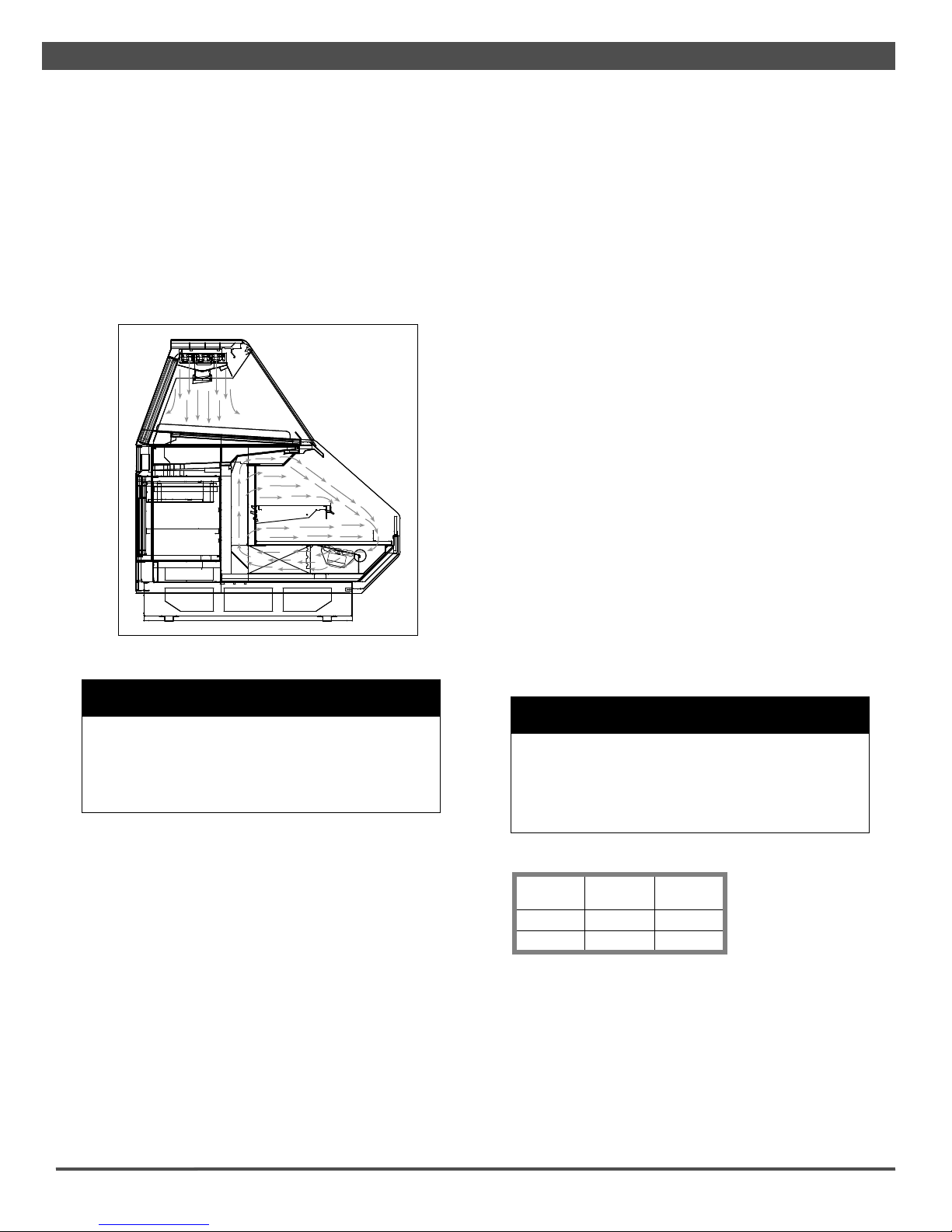
AIRFLOW & PRODUCT LOAD
Hillphoenix cases provide maximum product capacity within the
refrigerated air envelope. Please keep products within the ap-
propriate load limit.
It is important that you do not overload the food product display
so that it impinges on the air!ow pattern (Fig. 11). Overload-
ing will cause malfunction and the loss of proper temperature
levels, particularly when discharge and return air sections are
covered.
W A R N I N G
Always keep product within the designated air
curtain. Failure to do so may result in case
malfunction and product losing proper tempera-
ture, resulting in sub-standard operation and
increased chances of food contamination.
•
PTD-RGC cases are available with the defrost and temperature
controls mounted at the case or initiated by the rack controller.
When the controls are mounted at the case, the single time-off
defrost is initiated by the Dixell XR70CX controller mounted in
the slide out control box. During defrost, all valves close and
the pump cycles OFF. When in refrigeration mode, the glycol
!ow to the top coil, shelves and the Coolgenix pans is inde-
pendently controlled by the Dixell controller. If none of these
components requires !ow, all solenoids close (including DX
liquid-line valve) and the pump is cycled OFF.
When defrost and temperature are controlled from the rack,
the time-off defrost is controlled by a set of normally open con-
tacts at the rack controller. When in refrigeration mode, the
top coils, shelf and the Coolgenix pans are controlled as three
independent, temperature-controlled cases. Again, if none of
C A U T I O N
If the shelves are removed from the case or other-
wise not utilized, the shelf setpoint (SAA) must be
raised to 90 oF to prevent the pump from running
when only the shelves are calling for refrigeration.
Failure to do so could result in early pump failure.
•
these components requires !ow, all valves close and the pump
cycles OFF.
Whether the controls are managed at the case or by the rack
controller, the case and product temperatures are maintained
by having the top coils, shelves and the Coolgenix deck pans
cycle through their individual DIFFERENTIAL range. If the
Dixell XR70CX Controller is used, the !ow of the chilled !uid to
the Coolgenix pans, shelves and top coil circuit is controlled by
comparing the temperature readings of the appropriate tem-
perature sensor against either the CUT-IN or CUT-OUT setpoint
to the DIFFERENTIAL control settings. To determine CUT-OUT
temperature, calculate the CUT-IN minus the DIFFERENTIAL.
To determine CUT-IN temperature, calculate the CUT-OUT plus
the DIFFERENTIAL. For example, the factory setting for pan
CUT-OUT is 29°F with a 4°F DIFFERENTIAL which yields a CUT-
IN setting of 33°F.
The factory settings should be considered a guide and may
need to be adjusted based on store conditions. Because
these cases are often installed in stores near a meat prepara-
tion area where standard ASHRAE conditions may not apply,
different settings may be required for optimal operation.
It is important to consult the guidelines and control setting
shown on page 2 before setting defrost times. Further adjust-
ment may be required depending on store conditions.
If your case is equipped with a Dixell temperature and humidity
controller, see Appendices B1-B4 for operating instructions.
If you need to convert pressure to temperature see Appendix
C1 for the Sporlan Temperature-Pressure Chart.
DEFROST & TEMPERATURE CONTROLS
Cases are equipped with either Hot Gas or Timed-Off defrost at
the owner's option.
The hot gas defrost termination sensor bulb and probe are
attached to the dump line which is in the front, left-hand side
of the case.
Fig. 11 Airflow pattern
16
This manual suits for next models
1
Table of contents
Other Barker Merchandiser manuals

Popular Merchandiser manuals by other brands

True
True GDM-7-S-LD installation manual

Master Bilt
Master Bilt BEL-2-30 Specification sheet

Structural Concepts
Structural Concepts DO3623R Installation and operating manual

True
True GDIM-26 installation manual

Winco
Winco EDM-1K Operating instructions manual

Hatco
Hatco FLAV-R-FRESH FDW-1 Installation & operating manual


