Baroness FS1700 Operation manual

Read this manual and the owner's manual for the engine before using the machine.Required reading
Owner's operating manual
Serial No.10291- Ver.1.0
Riding Sweeper

1
Contents
Greeting ............................................................................................................2
Introduction .......................................................................................................2
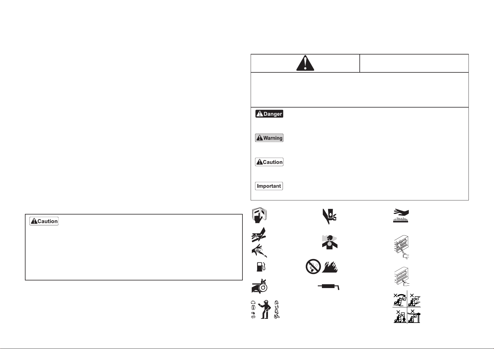
Warning Symbols ..............................................................................................2
Purpose.............................................................................................................3
Safety ................................................................................................................3
Safe Operating Practices ..................................................................................3
Training .............................................................................................................3
Preparation........................................................................................................3
Operation ..........................................................................................................4
Maintenance and Storage .................................................................................5
About the Waste Disposal.................................................................................5
Before Long-Term Storage................................................................................5
1. Precautions for Safe Operation.....................................................................6
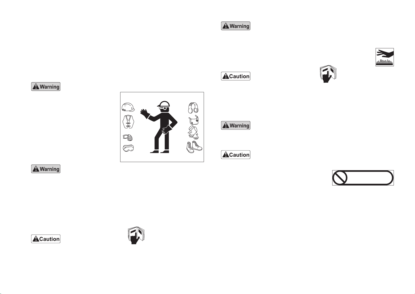
1-1 Clothes for Safe Operation .......................................................................6
1-2 Do Not Operate Under the Following Conditions......................................6
1-3 Do Not Modify Machine ............................................................................6
1-4 Removing Debris From Around Muer and Engine .................................6
1-5 When Lending to Others...........................................................................6
1-6 Do Not Drive or Operate at Night..............................................................6
1-7 Do Not Travel on Public Roads.................................................................6
2. Specications ................................................................................................7
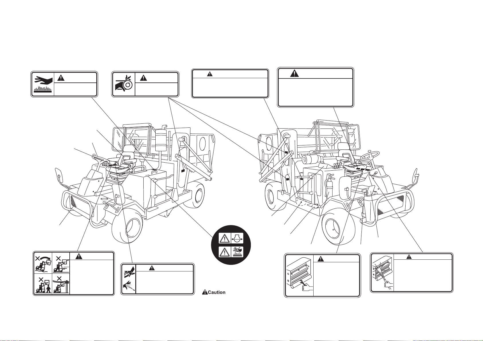
3. Names of Parts and Decal Positions.............................................................8
4. Inspection Before Use...................................................................................9
4-1 Cleaning of Radiator and Oil Cooler.........................................................9
4-2 Inspection of Radiator and Coolant Quantity............................................9
4-3 Inspection and Supply of Engine Oil.......................................................10
4-4 Inspection of Hydraulic Oil......................................................................10
4-5 Cleaning of Air Cleaner...........................................................................10
4-6 Inspection of Engine-Related Parts ........................................................11
4-7 Inspection of Tires...................................................................................11
5. Tightening the Parts ....................................................................................12
5-1 Tightening Torque ...................................................................................12
5-2 Tightening Torque by Model....................................................................13
6. Operation of Each Section ..........................................................................14
6-1 Precautions for Operating the Machine ..................................................14
6-2 Before Starting the Engine......................................................................14
6-3 Starting/Stopping the Engine..................................................................14
6-4 Precautions for Handling Fuel ................................................................15
6-5 Precautions When Leaving the Machine ................................................15
6-6 Control Box.............................................................................................15
6-7 Parking Brake .........................................................................................15
6-8 Adjustment of Seat..................................................................................16
6-9 Tilt Steering.............................................................................................16
7. Basic Operation...........................................................................................16
7-1 Traveling .................................................................................................16
7-2 Collection Work.......................................................................................17
7-3 Bucket Dumping .....................................................................................18
8. Instruments .................................................................................................19
8-1 Water Temperature Gauge .....................................................................19
8-2 Tachometer/Hour Meter ..........................................................................19
8-3 Fuel Gauge.............................................................................................20
8-4 Oil Pressure Lamp..................................................................................20
8-5 Charge Lamp..........................................................................................20
9. Maintenance/Inspection of Parts.................................................................20
9-1 Replacement of Engine Oil.....................................................................20
9-2 Greasing .................................................................................................21
9-3 Replacement of Hydraulic Oil .................................................................22
9-4 Inspection of Oil Leakage .......................................................................22
9-5 Inspection of Battery...............................................................................22
9-6 NTN Constant Velocity Joints .................................................................23
9-7 Opening/Closing of Hood........................................................................23
9-8 Jacking Up the Machine .........................................................................23
10. Maintenance Precautions..........................................................................24
10-1 Maintenance Precautions .....................................................................24
10-2 Preventing Injuries Caused by High-Pressure Oil ................................24
10-3 Maintenance Schedule .........................................................................24
11. Towing When the Machine Does Not Travel ............................................25
11-1 Towing When the Machine Does Not Travel .........................................25
12. Operating Precautions ..............................................................................25
12-1 Preparations Before Use ......................................................................25
12-2 Precautions for Rotating Parts..............................................................25
12-3 Precautions for Hot Parts......................................................................25
13. Operating on Slopes .................................................................................26
13-1 Precautions for Operating on Slopes....................................................26
14. Option ......................................................................................................26
14-1 Rear-view Monitor.................................................................................26
14-2 Hood .....................................................................................................26

2
Warning Symbols
This manual uses the following warning symbols for handling precautions that are
important for your safety.
Warning symbol
This symbol indicates the articles regarding “Danger,” “Warning,” or “Caution.”
Those articles describe important safety precautions and so read them carefully
to understand completely before operating the machine.
Failure to adequately follow these safety precautions may cause an accident.
This symbol indicates that serious injury or death will occur if the warning is ig-
nored.
This symbol indicates that serious injury or death may occur if the warning is ig-
nored.
This symbol indicates that injury or damage to property may occur if the warning
is ignored.
This symbol indicates precautions on the mechanism of the machine.
Greeting
Thank you for purchasing the Baroness machine.
This manual explains proper handling, adjustment, and inspection of your machine.
Prior to use, carefully read this manual to thoroughly understand the contents for
safe and correct operation.
We hope you will use the machine safely, and take advantage of its best perfor-
mance.
Introduction
Read this manual carefully to ensure that you thoroughly understand how to
properly operate and maintain this machine, and to avoid causing injury to yourself
or others.
The operator is responsible for operating the machine properly and safely.
Do not perform maintenance on the machine other than that described in this
manual.
Be sure to also read the Owner's Manual for the engine, battery, etc.
Maintenance should only be performed by a certifi ed specialist.
If you have any questions concerning maintenance or genuine parts, please contact
your local Baroness dealer or Kyoeisha.
When making inquiries about this machine, please specify the machine's model
designation and serial number.
When loaning or transferring this machine, please also provide this manual together
with the machine.
The information described in this manual is subject to change for improvement
without prior notice.
When replacing parts, be sure to use genuine Baroness parts or parts designated
by Kyoeisha.
Note that the Baroness product warranty may not apply to defects caused by the
use of parts from other companies.
… Caution symbol
(V-belt/rotating parts)
… Caution symbol
(Hot surface)
… Warning symbol
(High-pressure oil)
… See the Owner's
operating manual.
… Fuel
Diesel fuel
… Danger symbol
(Flammable)
… Caution symbol
(Pinching)
… Warning symbol
(Exhaust gas)
… Caution symbol
(Cleaning)
… Caution symbol
(Rotary brush)
… Warning symbol
(High dumping)
… Warning symbol
(Clothes for safe operation)
1. 2.
3. 4.
… Grease

3
Purpose
This machine is intended for sweeping at golf courses.
Do not use this machine in any way other than its intended purpose, and do not
modify the machine.
Operating this machine for other purposes and modifying it may be very dangerous
and may cause damage to the machine.
In addition, this machine is not authorized for operation as a special motor vehicle.
Do not operate it on public roads.
Safety
Failure to adequately follow these safety precautions may cause an accident result-
ing in injury or death.
Safe Operating Practices
The following instructions include the ones from CEN standard EN 836: 1997, ISO
standard 5395: 1990, and ANSI B71.4-2004.
Training
1.Read this manual and other training material carefully. Be familiar with the con-
trols, safety signs, and the proper use of the equipment.
2.If the operator or mechanic can not read English it is the owner's responsibility to
explain this manual to them.
3.All operators and mechanics should seek and obtain professional and practical
instruction.
The owner is responsible for training the users.
Such instruction should emphasize.
[1]The need for care and concentration when working with ride-on machines.
[2]Control of a ride-on machine sliding on a slope will not be regained by the ap-
plication of the brake.
The main reasons for loss of control are
-Insucient wheel grip
-Being driven too fast
-Inadequate braking
-The type of machine is unsuitable for its task
-Lack of awareness of the eect of ground conditions, especially slopes
-Incorrect hitching and load distribution
4.Never allow children or people unfamiliar with these instructions to use or service
the machine.
Local regulations may restrict the age of the operator.
5.The owner/use can prevent and is responsible for accidents or injuries occurring
to themselves, other people, or property.
6.Keep in mind that the owner, operator, and mechanic are responsible for acci-
dents or hazards occurring to other people or their property.
Preparation
1.Evaluate the terrain to determine what accessories and attachments are needed
to properly and safety perform the job.
Only use accessories and attachments approved by the manufacturer.
2.While operating, always wear substantial footwear, long trousers, hard hat, safe-
ty glasses, and ear protection.
Long hair, loose clothing, or jewelry may get tangled in moving parts.
Do not operate the equipment when barefoot or wearing open sandals.
3.Inspect the area where the equipment is to be used and remove all objects such
as rocks, toys and wire which can be thrown by the machine.
4.Exercise care in the handling of fuel.
[1]Store fuel in containers specically designed for this purpose.
[2]Add fuel before starting the engine.
Never remove the cap of the fuel tank or add fuel while the engine is running
or when the engine is hot.
[3]Refuel outdoors only and do not smoke while refueling.
[4]If fuel is spilled, do not attempt to start the engine but move the machine
away from the area of spillage and avoid creating any source of ignition until
petrol vapours have dissipated.
[5]Replace all fuel tanks and container caps securely.
This machine is designed to ensure safe operation and has been tested and in-
spected thoroughly before shipment from the factory.
The machine is equipped with safety devices to prevent accidents.
However, whether the machine demonstrates its original performance level de-
pends on the manner in which it is operated and handled, as well as the man-
ner in which it is managed on a daily basis.
Inappropriate use or management of the machine may result in injury or death.
Observe the following safety instructions to ensure safe operation.
Warning-Fuel is highly ammable.
Take the following precautions.

4
5.Check that operator's presence controls, safety switches and shields are at-
tached and functioning properly.
Do not operate unless they are functioning properly.
6.If the brake operation is faulty or the parking brake lever has noticeable play, be
sure to adjust or repair them before operating the machine.
7.Replace faulty muers.
Operation
1.Do not operate the engine in a conned space where dangerous carbon monox-
ide fumes can collect.
2.Only operate in good light, keeping away from holes and hidden hazards.
3.Before attempting to start the engine, disengage all attachments, shift into neu-
tral, and engage the parking brake.
Only start engine from the operator`s position.
Use seat belts if provided.
4.Remember there is no such thing as a safe slope. Travel on grass slopes re-
quires particular care.
To guard against overturning:
[1]Do not stop or start suddenly when going up or downhill.
[2]Engage clutch slowly, always keep machine in gear, especially when traveling
downhill.
[3]Machine speeds should be kept low on slopes and during tight turns.
[4]Stay alert for humps and hollows and other hidden hazards.
[5]Never operate across the face of the slope, unless the machine is designed
for this purpose.
[6]Never drive the machine on a slope with an angle of gradient that is greater
than that specied or in a place where there is a danger of the machine slip-
ping.
5.Never operate the machine with damaged guards, shields, or without safety pro-
tective devices in place.
Be sure all interlocks are attached, adjusted and functioning properly.
6.Do not change the engine governor settings or overspeed the engine. Operating
the engine at excessive speed may increase the hazard of personal injury.
7.Do the following before leaving the operator`s position.
[1]Stop on level ground.
[2]Disengage the power take-o and lower the attachments.
[3]Change into neutral and set the parking brake.
[4]Stop the engine and remove the key.
8.Disengage the drive to attachments, stop the engine, and remove the ignition
key in the following conditions.
[1]Before refueling.
[2]Before making height adjustment unless adjustment can be made from the
operator's position.
[3]Before cleaning blockages.
[4]Before checking, cleaning, or working the machine.
[5]After striking a foreign object or if an abnormal vibration occurs.
Inspect the machine for damage and make repairs before restarting and op-
erating the equipment.
9.Keep hands and feet away from the cutting units and the rotating parts.
10.Look behind and down before backing up to be sure of a clear path.
11.Do not carry passengers.
12.Never operate while people, especially children, or pets are nearby.
13.Slow down and use caution when making turns and crossing roads and side-
walks.
14.Disengage drive to attachments when transporting or not in use.
15.When using any attachments, never direct discharge of material toward bystand-
ers nor allow anyone near the machine while in operation.
16.Do not operate the machine under the inuence of alcohol or drugs.
17.Take care when loading or unloading the machine into a trailer or a truck. Load
or unload the machine in a at and safe place. Before loading or unloading, set
the parking brake on the truck or trailer, stop the engine, and chock the wheels.
When transporting the machine on a truck or a trailer, set the parking brake, stop
the engine, and fasten the machine to the truck with a rope or other suitable re-
straining device that has sucient strength.
When using a loading ramp, select one with sucient strength, length, and width
and that will not cause the machine to slip.
18.Close the fuel valve before transporting the machine.
19.Use care when approaching blind corners, shrubs, trees, or other objects that
may obscure vision.
20.Do not take your eyes o the road ahead. Do not operate the machine with no
hands.
21.Reduce the throttle setting during engine run-out and, if the engine is provided
with a shut-o valve, turn the fuel o at the conclusion of operation.

5
Maintenance and Storage
1.Disengage drives on level ground, lower the atattachments, set parking brake,
stop engine and remove key from ignition.
Wait for all movement to stop before adjusting, cleaning or repairing.
2.When machine is to be parked, stored, or left unattended, lower bucket.
3.To reduce the fi re hazard, keep the engine, silencer/muffl er, battery compartment
fuel storage area, cutting units and drives free of grass, leaves, or excessive
grease.
Clean up oil or fuel spillage.
4.Allow the engine to cool before storing in any enclosure.
5.Only cover the machine with a sheet after hot parts have sufficiently cooled
down.
6.Never store the equipment with fuel in the tank inside a building where fumes
may reach an open fl ame or spark.
7.If the engine is provided with a shut-off valve, shut off valve while storing or
transporting.
8.Do not store fuel near fl ames.
9.Never allow untrained personnel to service machine.
10.Allow the engine/muffl er to cool before checking/maintenance.
11.Appropriately manage and correctly use the tools necessary for servicing or ad-
justing the machine.
12.Use jack stands to support components when required.
13.Carefully release pressure from components with stored energy.
14.Be sure to depressurize the hydraulic system before performing maintenance
operations on it such as removing hydraulic equipment.
15.Check whether line connectors in the hydraulic system are properly tightened.
Before applying hydraulic pressure, check the connections of the hydraulic pres-
sure lines and the condition of the hoses.
16.When checking the hydraulic circuit for pinhole leaks or oil leakage from nozzles,
do not use your hands.
Use items such as paper or corrugated cardboard to fi nd leakage points.
Be extremely careful with high-pressure oil as it may pierce your skin, result.
If fl uid is injected into the skin it must be surgically removed within a few hours
by a doctor familiar with this form of injury or gangrene may result.
17.Disconnect battery before making any repairs.
Disconnect the negative terminal fi rst and the positive last.
Reconnect positive fi rst and negative last.
18.Make sure that parts such as wires are not touching each other and that their
covers have not come off .
19.Keep hands and feet away from moving parts.
If possible, do not make adjustments with the engine running.
20.Charge batteries in an open well ventilated area, away from spark and fl ames.
Unplug charger before connecting or disconnecting from battery.
Wear protective clothing and use insulated tools.
21.Keep all parts in good working condition and all hardware tightened.
Replace all worn or damaged decals.
22.Keep all nuts, bolts and screws tight to be sure the equipment is in safe working
condition.
23.If the fuel tank has to be drained, do this outdoors.
About the Waste Disposal
Make sure that waste generated when servicing or repairing the machine is dis-
posed of in accordance with local regulations.
(e.g. waste oil, antifreeze batteries, rubber products, and wires etc.)
Before Long-Term Storage
For details, refer to the Engine Handling Manual and Battery Instruction Manual.
● Remove dirt, grass clippings, debris, oil stains etc. completely.
● Supply oil and apply grease to appropriate parts.
● Remove the negative battery wire.
● Removing fuel
Remove the fuel from the fuel tank and related electrical parts.
● Cleaning and replacing oil
Clean the machine and engine, and then inspect and replace the engine oil and
air cleaner oil and element.
● Oiling
Oil the various sliding parts.
● Battery
Remove the battery from the machine, recharge it, and then store it in a
well-ventilated indoor location.
● Tire pneumatic pressure
Set the tire air pressure slightly higher than normal, and then place the machine
on a board to avoid humidity.
● Storage location
Cover the machine and store it in a dry place where it will not be exposed to
rain.

6
1-4 Removing Debris From Around Muer and Engine
Debris, such as grass cuttings, accumulates in the engine air intake, air cleaner
intake, muer and exhaust pipe, which may cause malfunction of the engine or
a re due to overheating. If this occurs, immediately stop operation,
and then wait for overheating parts to cool down completely before
removing the debris.
1-5 When Lending to Others
Lending the machine to others may result in an unexpected accident if they have
no knowledge of the safety precautions and handling instructions described in
this manual. To prevent such an accident, you should explain the operating pro-
cedure and give this manual to the person who is borrowing the machine. Then,
make sure the person reads this manual thoroughly before using it.
1-6 Do Not Drive or Operate at Night
Do not travel or operate the machine under poor visibility such as at night or in
bad weather.
1-7 Do Not Travel on Public Roads
This machine is not authorized as a special motor vehicle. Do not drive it on
public roads.
1. Precautions for Safe Operation
This is a machine that uses brushes rotating at high speed. In addition, various
operating locations, harsh conditions (vibration, slopes and dust), obstacles
and lawn conditions may be encountered. Therefore, operators are required to
thoroughly inspect and maintain the machine as well as become familiar with
the operating procedures. As the manufacturer, we strongly recommend that the
machine be operated correctly with safety rst in mind in order to ensure your own
safety and that of others.
1-1 Clothes for Safe Operation
For safety, wear suitable clothes that
cannot get caught in the machine.
Also wear appropriate protective gear,
safety glasses, footwear, a helmet, and
gloves etc.
There is a danger of clothing with very
long strings, such as an apron or tow-
el, becoming caught or pulled into the
machine.
1-2 Do Not Operate Under the Following Conditions
● Do not use the machine when you are tired. If you get tired while using the ma-
chine, stop working and take a break.
● Do not use the machine when feeling sick, after drinking alcohol, or under the
inuence of medication. These conditions will adversely aect your vision, alert-
ness, and judgment.
● If you are unfamiliar with the machine, be sure to understand the operating pro-
cedures and safety precautions before using it. In addition, do not allow children
to use the machine.
1-3 Do Not Modify Machine
Do not modify the machine. Only use replacement parts as well as oil and
grease recommended by Baroness. If you modify the machine or drive it with
parts that are not recommended by Baroness, it may cause damage to the ma-
chine or an injury.
බ㐨㌴⚗Ṇ
.

7
*
The factory default maximum engine rpm is 2,400 rpm.
2. Specications
Model FS1700
Dimensions
Total length 385 cm
Total width 213 cm
Total height
Roof 221 cm
Steering wheel
149 cm
Weight
Machine
(empty fuel tank)
During operation
1,851 kg
During transport
2,238 kg
Minimum turning radius 490 cm
Engine
Model Kubota V2403-M
Type
Vertical Water-cooled 4-cycle diesel engine
Total displacement 2,434 cm3(2.434 L)
Maximum output 31.2 kW(42.4 PS)/2,400 rpm
Fuel tank capacity Diesel 40.0 dm3(40.0 L)
Fuel consumption 237g/kW h (rated output)
Engine oil capacity 1.6 dm3(1.6 L)
Operating width (Mowing width) 150 cm
Operating height (Mowing height) -
Bucket capacity 2,100 dm3(2,100 L)
Drive Traveling HST (2WD/4WD selectable)
Mowing Hydraulic, Mechanical
Speed (HST)
Forward 2WD: 0 – 18.0 km/h 4WD: 0 – 9.0 km/h
Reverse -
Speed (Mechanical) -
Eciency
10,800 m2/h (4WD: 9.0 km/h x operating width x 0.8)
Maximum inclination for operation 20 degrees
Tire size Front wheel 23.0 x 10.50 - 12
Rear wheel 26.5 x 14.00 - 12
Tire pneumatic
pressure
Front wheel 150 kPa (1.5 kgf/cm2)
Rear wheel 150 kPa (1.5 kgf/cm2)
Battery 105D31R

8
注 意
運転中及び運転停止直後にカバー
やマフラーにふれないで下さい。
やけどをする危険があります。
K4205000560
警 告
高圧オイルによる被害の防止
・高圧オイルが皮膚に吹き付けられると、重大な損傷が起きます。
・高圧ライン・ホース・接手を外す前に、圧力を逃がすこと。
・運転を始める前に(高圧になる前に)全ての接手の締め具合を
確認すること。
・高圧ラインの小穴ノズルには、手や身体を近づけないこと。
・漏れの点検には、小さな厚紙を使うこと。
・もし、高圧オイルが皮膚に吹き付けられたら、2〜3時間以内
に医師の手当を受けなければなりません。
K4205000390
・作業部の洗浄
・作業終了後は、速やかに各部の水洗いによる洗浄を
行なってください。
・洗浄箇所→ロータリーケース内外、ロータリー
ブラシ、ロータリー板、ロータリーローラー、
バケット内外、タイヤ、フレーム等
・エンジン部、油圧部、バッテリ部は水洗いせず、布
やブラシ、エア等で泥や埃を落としてください。
・洗浄後は、しっかり乾燥させ、各注油箇所には注油
を行ってください。
・洗浄を怠ると、次回作業時に支障を来したり、故障
や危険な事故へとつながる恐れがあります。
注 意
K4205001210
注 意
・ロータリーブラシの交換は全部
同時に新品と取り替えてくださ
い。一部だけの交換は重量バラ
ンスが崩れ、危険ですので、絶
対に行なわないでください。ロ
ータリー板も同様です。
・作業前にボルト、ナットの増し
締めチェックを必ず行なってく
ださい。ボルト、ナットが緩んだ
まま作業すると大変危険です。
K4205001200
・この機械を運転する前に取扱い説明書を熟読し十分機械の
操作を理解してから運転して下さい。
・危険・警告・注意等ラベルの指示にしたがって行動しない
と死傷又はケガをする結果となります。
・マークやラベルの説明文はきれいに保ち、無くなったり損
傷があった場合には、新しいものに交換して下さい。
注 意
取扱上の注意
K4205000630
注 意
動力作動中は回転物に触れないで
下さい。ベルトや回転物で指や手
をケガをする危険があります。
K4205000670
注 意
油圧作動油交換について
1・作動油の交換は、1年又は500時間の短い方で交換して下さい。
2・フィルターは、作動油交換時合わせて交換して下さい。
3・作動油が乳化および透明度が悪くなった時は即交換して下さい。
4・作動油補充は、指定銘柄作動油を補充して下さい。
K4205000420
1. 2.
3. 4.
−ハイダンプ(バケット上げ)作動の禁止状況−
警 告
K4205001420
1.軟弱地、不整地や傾斜地上でのハイダンプは
車体のバランスがくずれ大変危険ですので、
絶対行わないこと。
2.本体が走行中でのハイダンプは、車体のバラ
ンスがくずれ、大変危険ですので絶対に行な
わないこと。
3.周囲に作業の障害となる人や動物や車などが
あるとき。
4.頭上に電線や立木など作業中ぶつかりそうな
障害物があるとき。
Drain plug
K4205001200
DECAL, CAUTION FOR
ROTARY BRUSH
Forward pedal
Radiator
Reverse pedal
Control box
Cartridge filter
Fire extinguisher
K4205001210
DECAL, CAUTION FOR
CLEANING
K4205000390
DECAL, WARNING FOR
HIGH-PRESSURE OIL
K4205001970
DECAL, CAUTION FOR HIGH
TEMPERATURES AND
SPOUTING COOLANT
Battery
Throttle Lever
Steering handle
Seat
K4205001420
DECAL, WARNING FOR
HIGH DUMPING
K4205000560
DECAL, CAUTION MUFFLER
K4205000420
DECAL, CAUTION USAGE OF OIL
K4205000670
DECAL, CAUTION
ROTATING BELT
K4205000630
DECAL, HANDLING PRECAUTIONS
CAUTION FOR SPOUTING
COOLANT. DO NOT OPEN
WHILE HOT.
K4205001970
3. Names of Parts and Decal Positions

9
4. Inspection Before Use
Be sure to inspect the following before starting the machine.
4-1 Cleaning of Radiator and Oil Cooler
● Blow air to clean any debris that may be attached to the radiator, oil cooler or
antidust mesh.
An unclean radiator, oil cooler or antidust mesh may cause failure of the
hydraulic equipments or overheating or damage to the engine.
Antidust mesh
Dust-proof plate
4-2 Inspection of Radiator and Coolant Quantity
Perform the inspection after the engine has cooled down.
The radiator cap is pressurized. If you remove the radiator cap while
the engine is overheated, hot steam will burst out, possibly resulting in
burns. Make sure that the water temperature and pressure are reduced,
and then grab the cap with a thick cloth and gradually turn the cap
counterclockwise to loosen and remove it.
● Make sure that the coolant level in the reserve tank is between "FULL" and
"LOW".
If the coolant level is lower than the "LOW" mark, open the reserve tank cap and
supply coolant up to the "FULL" mark. If no coolant is in the reserve tank, further
more, open the radiator cap and supply coolant up to the opening.
Do not open the radiator cap during normal inspections.
● When supplying coolant, be sure to use clean water.
● Before winter, drain the coolant or add antifreeze.
Relationship between concentration of long-life coolant (LLC) and freezing
temperature
Freezing temperature
LLC concentration(volume %)
Down to -10°C (14°F) 20 %
Down to -15°C (5°F) 30 %
Down to -20°C (-4°F) 35 %
Down to -25°C (-13°F) 40 %
A
Cap
Reserve tank Drain plug
View from A
Oil cooler

10
4-4 Inspection of Hydraulic Oil
● Position the machine so it is level, and
then check that the oil level reaches
the middle of the oil gauge. Supply oil
if it is at an insucient level.
● When supplying hydraulic oil, use Shell
Tellus S2M46 or equivalent.
4-5 Cleaning of Air Cleaner
● A contaminated air cleaner element
may cause malfunction of the engine.
If the air cleaner element is contami-
nated, pay close attention not to dam-
age it and lightly tap a solid portion of
the element or blow air from its inside.
● Inspect the air cleaner by checking the
vacuum indicator.
If the air cleaner element is contami-
nated, the vacuum indicator will display
a red ring. In that case, remove the
element and clean it.
● Change the air cleaner element after
every 200 hours of operation.
After cleaning the element, install it,
and then press the reset button.
Oil gauge
4-3 Inspection and Supply of Engine Oil
● Position the machine so that the engine is level, and then check the oil level with
the oil level gauge.
The appropriate oil level should be between the upper and lower limit lines on
the gauge.
● Supply oil if it is at an insucient level, or replace the oil if it is dirty.
● Before checking the oil level, stop the engine, and wait 10 to 20 minutes for the
engine to cool down.
● Do not supply too much engine oil. Otherwise, the engine may be damaged or
malfunction.
● Engine oil is supplied through the oil
lling port.
●Be sure to use engine oil that is classi-
ed as API Service Grade CF or high-
er, with an SAE Viscosity that is appro-
priate for the operating environment
(ambient temperature).
●It will take a while for the supplied en-
gine oil to descend into the oil pan.
Check the oil level again 10 to 20 min-
utes after supplying the oil.
Oil level gauge
Upper
limit Lower
limit
Oil filler cap
Vacuum indicator
Reset button

11
Pneumatic pressure
Standard tires
Front wheel: 150 kPa (1.5 kgf/cm2)
Rear wheel: 150 kPa (1.5 kgf/cm2)
4-6 Inspection of Engine-Related Parts
… For details on handling the engine, please refer to the separate Engine
Handling Manual.
● Check the fuel system parts for cracks and leakage. Replace parts if necessary.
● Blow air to clean any grass, leaves or ammable materials that may be attached
inside or around the muer.
4-7 Inspection of Tires
● Check the pneumatic pressure of the tires, and make sure that there are no
cracks, damage or abnormal wear.

12
Nominal
diameter
General bolt
Strength classication 4.8
N-m kgf-cm lb-in
M5 3 - 5 30.59 - 50.99 26.55 - 44.26
M6 7 - 9 71.38 - 91.77 61.96 - 79.66
M8 14 - 19 142.76 - 193.74 123.91 - 168.17
M10 29 - 38 295.71 - 387.49 256.68 - 336.34
M12 52 - 67 530.24 - 683.20 460.25 - 593.02
M14 70 - 94 713.79 - 958.52 619.57 - 831.99
M16 88 - 112 897.34 - 1142.06 778.89 - 991.31
M18 116 - 144 1,182.85 - 1,468.37 1,026.72 - 1,274.54
M20 147 - 183 1,498.96 - 1,866.05 1,301.10 - 1,619.73
M22 295 3,008.12 2,611.05
M24 370 3,772.89 3,274.87
M27 550 5,608.35 4,868.05
M30 740 7,545.78 6,549.74
Nominal
diameter
Heat-treated bolt
Strength classication 8.8 Strength classication 10.9
N-m kgf-cm lb-in N-m kgf-cm lb-in
M5 5 - 7 50.99 - 71.38 44.26 - 61.96 7 - 10 71.38 - 101.97 61.96 - 88.51
M6 8 - 11 81.58 - 112.17 70.81 - 97.36 14 - 18 142.76 - 183.55 123.91 - 159.32
M8 23 - 29 234.53 - 295.71 203.57 - 256.68 28 - 38 285.52 - 387.49 247.83 - 336.34
M10 45 - 57 458.87 - 581.23 398.30 - 504.51 58 - 76 591.43 - 774.97 513.36 - 672.68
M12 67 - 85 683.20 - 866.75 593.02 - 752.34 104 - 134 1,060.49 - 1,366.40 920.50 - 1186.03
M14 106 - 134 1,080.88 - 1,366.40 938.21 - 1,186.03 140 - 188 1,427.58 - 1,917.04 1,239.14 - 1,663.99
M16 152 - 188 1,549.94 - 1,917.04 1,345.35 - 1,663.99 210 - 260 2,141.37 - 2,651.22 1,858.71 - 2,301.26
M18 200 - 240 2,039.40 - 2,447.28 1,770.20 - 2,124.24 280 - 340 2,855.16 - 3,466.98 2,478.28 - 3,009.34
M20 245 - 295 2,498.27 - 3,008.12 2,168.50 - 2,611.05 370 - 450 3,772.89 - 4,588.65 3,274.87 - 3,982.95
M22 - - - 530 5,404.41 4,691.03
M24 - - - 670 6,831.99 5,930.17
M27 - - - 1,000 10,197.00 8,851.00
M30 - - - 1,340 14,628.78 11,860.34
M4 T
4.8
5. Tightening the Parts
A number of bolts are used in each part of this machine. be sure to re-tighten the bolts and nuts, because they may be loosened at the earlier stage of the use.
5-1 Tightening Torque
As to the bolts and nuts without any special instruction, tighten them in appropriate tightening torque with proper tool.
Too much tightening may cause the looseness or damage of the screw.
The strength of tightening is determined by types of screws, strength, the friction of thread face or base face and others.
The table below is for the galvanized or parkerized bolts.
In case that the strength of internal thread is weak, it is not applied.
Do not use rusty or sand attached “screw.”
Otherwise, it may cause insucient tightening even if you apply the specied tightening torque.
The friction of the screw face becomes higher and the tightening torque is canceled out by the friction, therefore sucient tightening cannot be applied.
If “screw” is wet by water or oil, do not tighten it with normal tightening torque.
If the screw is wet, the torque coecient will get smaller and it may result in too much tightening.
Too much tightening may cause looseness by the screw stretched or result in damage.
Do not use a bolt experienced too much burden.
Using the impact wrench requires the skill.
Do exercise as much as possible for steady tightening.
8 T
8.8
811T
10.9
11

13
Location Code Part name Tightening torque Thread locking
adhesive
N-m kgf-cm lb-in
Front wheel
Motor K0010140601 BOLT, HT M14-60 100 1,019.70 885.10
Wheel mounting base
-
NUT, SLOTTED FOR HYDRAULIC MOTOR (1・1/4-18UNF)
400 - 430 4,078.80 - 4,384.71 3,540.40 - 3,805.93
Wheel K0011140352 BOLT, HT P1.5 M14-35 106 - 134 1,080.88 - 1,366.39 938.20 - 1,186.03
Rear wheel
Motor K0010140601 BOLT, HT M14-60 100 1,019.70 885.10
Wheel mounting base
-
NUT, SLOTTED FOR HYDRAULIC MOTOR (1・1/4-18UNF)
400 - 430 4,078.80 - 4,384.71 3,540.40 - 3,805.93
Wheel K0034120352 BOLT, 8T P1.5 M12-35 67 - 85 689.19 - 866.74 593.01 - 752.33
Tie rod K1610000020 TIE-ROD END ASSY, MALE (R) 45 458.86 398.29
K1611000020
TIE-ROD END ASSY, LEFT-HANDED MALE (L)
45 458.86 398.29
Kingpin stopper K0011160902 BOLT, HT P1.5 M16-90 88 - 112 897.33 - 1,142.06 778.88 - 991.31
Piston pump K0010120502 BOLT, HT M12-50 67 - 134 683.19 - 1,366.39 593.01 - 1,186.03
Frame part B Sub frame K0010140702 BOLT, HT M14-70 70 - 94 713.79 - 958.51 619.57 - 831.99
K0010160952 BOLT, HT M16-95 88 - 112 897.33 - 1,142.06 778.88 - 991.31
Pedal part Trunnion lever K0010060202 BOLT, HT M6-20 14 - 18 142.75 - 183.54 123.91 - 159.31 ○
Brush part A K0010140302 BOLT, HT M14-30 70 - 94 713.79 - 958.51 619.57 - 831.99
K0010140802 BOLT, HT M14-80 70 - 94 713.79 - 958.51 619.57 - 831.99
Engine
K0012120352 BOLT, HT P1.25 M12-35 67 - 134 683.19 - 1,366.39 593.01 - 1,186.03
K0011100302 BOLT, HT P1.25 M10-30 45 - 76 458.86 - 774.97 398.29 - 672.67
K0013121102 BOLT, HT M12-110 67 - 134 683.19 - 1,366.39 593.01 - 1,186.03 ○
Coupling
K0024100401 BOLT, WITH HEX. HOLE M10-40 80 815.76 708.08
K0011100302 BOLT, HT P1.25 M10-30 45 - 76 458.86 - 774.97 398.29 - 672.67 ○
K0011100252 BOLT, HT P1.25 M10-25 45 - 76 458.86 - 774.97 398.29 - 672.67
K0013100402 BOLT, HT M10-40 45 - 76 458.86 - 774.97 398.29 - 672.67
5-2 Tightening Torque by Model
FS1700
Tighten the following bolts and nuts at the torque specied in the table.
For thread locking adhesive, apply a middle strength thread locker (ThreeBond 1322 anaerobic adhesives).

14
6. Operation of Each Section
6-1 Precautions for Operating the Machine
●Before you start operating the machine, make sure that each part functions
well. In particular, make sure that there is no abnormality with the brake, tires or
steering.
● Drive the machine at a speed that allows you to stop immediately in an emer-
gency in any situation.
● Remove any obstacles in the operating area so that neither the operator nor any
bystanders will be injured.
6-2 Before Starting the Engine
● Before starting the engine, be sure to read and fully understand the
Engine Handling Manual.
● Make sure that there are no other people or obstacles around the ma-
chine.
● Make sure that the covers are correctly in place and are not damaged.
● Do not start the engine in a building with insucient ventilation.
6-3 Starting/Stopping the Engine
● Procedure to Start Engine
1
Sit on the seat.
2
Set the parking brake switch to the "ON"
position.
3
Set the brush rotation switch to the "OFF"
position.
4
Take your foot o the pedals.
5
Slightly pull the throttle lever toward you
from "LOW".
6
Turn the key clockwise to the "Glow"
position to turn on the thermo-start lamp
and preheat the combustion chamber of
the diesel engine.
7
After the thermo-start lamp turns off,
immediately set the ignition key to the
"START" position.
8
When the starter starts rotating and the engine starts, slowly return the ignition
key to the "ON" position.
99
Make sure that the charge lamp and engine oil pressure lamp turn o. If they do
not turn o, stop the engine and inspect the machine.
●Do not touch rotating parts such as fan belts and pulleys while the en-
gine is running.
● Starter operation must take 15 seconds or less. If the engine still does
not start, stop using the battery for 30 to 60 seconds to avoid exhaust-
ing the battery.
● Procedure to Stop Engine
1
Set the traveling pedal in neutral position.
2
Apply the parking brake.
3
Move the throttle lever to "Low", and continue idling for 1-2 minutes.
4
Switch the ignition key to the "OFF" position.
5
Make sure that the engine has stopped.
6
Remove the ignition key.
7
Leave the driver's seat.
8
Close the fuel cock.
OFF ON
GLOW
START
チャージ
サーモスタート
エンジン油圧
Thermo-start lamp
Quickly returning the ignition key from
the "START" position to the "ON"
position may result in damage to the
machine.

15
● Interlock System (Safety Mechanisms)
1The engine will not start unless you are seated, the parking brake switch is set
to the "ON" position, the brush rotation switch is set to the "OFF" position, and
the traveling pedals are in the neutral position.
2The engine will stop if you set the parking brake switch to the "OFF" position
and leave the seat.
* If you leave the seat while the engine is running, set the parking brake switch to
the "ON" position.
3Even if you set the parking brake switch to the "ON" position before leaving the
seat, the engine will stop if the brush rotation switch remains set to the "ON" po-
sition.
* If you leave the seat while the engine is running, set the parking brake switch to
the "ON" position and the brush rotation switch to the "OFF" position.
4Even if you set the parking brake switch to the "ON" position before leaving the
seat, the engine will stop if a traveling pedal is depressed.
* If you leave the seat while the engine is running, set the parking brake switch to
the "ON" position and the traveling pedals to the neutral positions.
6-4 Precautions for Handling Fuel
● Keep away from fi re while refueling.
Extinguish all open fl ames and do not smoke.
● Supply fuel outdoors after stopping the engine and allowing it to cool
down completely.
● In order to prevent fi res, keep the machine clean, and remove accu-
mulated dirt, grease and oil.
● Wipe off any spilled fuel.
bcd
ef
g
kh
ij
a
6-5 Precautions When Leaving the Machine
1Stop the machine on level ground, and then apply the parking brake.
2Stop the rotation of the brushes, and completely lower the operating unit and
bucket.
3Stop the engine.
4Remove the key, and then leave the machine.
5If the brake feels weak, use the wheel stoppers to secure the machine.
Never park the machine on a slope.
6-6 Control Box
● The control box is located to the right of the seat.
a. Tachometer/hour meter
b. Water temperature gauge
c. Fuel system
d. Pilot lamps
e. Brush rotation switch
f. 2WD/4WD selector switch
g. Parking brake switch
h. Diff -lock switch
i. Buzzer ON/OFF switch
j. Buzzer selector switch
k. Throttle lever
Before operating the controls in the control box, make sure that there
are no people around the machine.
6-7 Parking Brake
● The parking brake switch is located at
the center of the control box.
To park the machine, set it to the "ON"
position.
Be sure to release the parking
brake before driving.
Otherwise, hydraulic equip-
ment may be damaged.
Diesel fuel
Parking brake switch
Seat
Brush rotation switch
Traveling Pedal
ONSeated OFF Neutral
Safety mechanism operating conditions
Safety mechanism operation
Start the engine
OFFAway - -
Stop the engine
ONAway ON -
Stop the engine
ONAway - Depress
Stop the engine
1
3
4
2
OFF ON
Parking brake
switch

16
7. Basic Operation
7-1 Traveling
● By means of hydraulic variable speed
drive the machine travels forward when
the forward pedal is depressed and
travels backward when the reverse
pedal is depressed.
● When collecting over bumpy surfaces,
reduce the operating speed. Simply re-
duce the traveling speed while keeping
the engine rpm steady.
Operating the machine on public roads is legally prohibited.
Before backing up, look behind you to check that the path is clear and
that you can back up safely.
Since turf tires have a lower pneumatic pressure than standard tires,
suciently reduce the traveling speed when turning.
● Otherwise, the sidewalls may be damaged or burst.
1) 2WD/4WD Selection
● This machine can be operated in 2WD
or 4WD, and the appropriate drive
type can be selected according to the
operating conditions. Use the switch in
the control box on the right side of the
seat.
* See “6-6 Control Box”.
For safety, 2WD/4WD selection can only be done while the pedals are
in the neutral positions. Therefore, stop the machine before switching
between 2WD and 4WD operation.
6-8 Adjustment of Seat
● Use lever
1
to adjust the seat back
and forth.
● Use lever
2
to adjust the angle of the
backrest.
● Turn handle
3
to adjust the rmness
of the seat suspension. Observe scale
4
while making adjustments. (50 to
130 kg)
● Turn knob
5
to adjust the angle of the
armrests.
● Lift the seat to adjust its height to one
of three positions.
6-9 Tilt Steering
The angle of the steering wheel can be ad-
justed.
Pull the tilt lever toward you to release the
lock, and then adjust the steering wheel.
Hold the steering wheel at the desired an-
gle, and then push the tilt lever forward to
lock it in place.
Be sure the steering wheel
position is securely locked. It
would be extremely dangerous
if it becomes loose while trav-
eling.
Steering wheel
Tilt lever
Lock
Release
3 positions
2WD
4WD
2WD/4WD selector switch
Forward pedal
Reverse pedal

17
2) Dierential Lock Mechanism
● This machine is equipped with a dif-
ferential lock mechanism. Use it when
caught in mud and the wheels are
spinning, even though the machine
is in 4WD. The dierential lock works
only in 4WD.
● Since lawns may be scraped while making turns with the dierential lock ap-
plied, set it to the "OFF" position before turning.
7-2 Collection Work
●Perform collection work with the engine rpm set between 2,000 and 2,200 rpm.
●Before beginning collection work, be sure to perform a safety check of the in-
tended operating area.
● Make sure there are no dangerous areas such as drop-os or steep slopes.
● Make sure there are no obstacles, such as people, animals or vehicles, in the
operating area.
● Make sure there are no overhead obstacles, such as trees or power lines.
●For safe operation, exclude dangerous areas and either remove obstacles or
people in advance or clearly indicate operating area boundaries with ags or
ropes to keep people from entering the area. Be sure to work safely and in safe
areas.
Bucket Up/Down Lever
Bucket Open/Close
Lever
Brush Up/Down Lever
OFF
ON
Diff-lock switch
1) Brush Rotation
1
The engine rpm should be set be-
tween 2,000 and 2,200 rpm.
2
When the brush rotation switch is
set to the "ON" position, the brushes
rotate. When it is set to the "OFF"
position, the brushes stop.
● When the brush rotation switch is set to the "ON" position, set the engine rpm
between 2,000 and 2,200 rpm.
2) Raising/Lowering of Brushes
1
When the brush up/down lever is
shifted toward
Up
, the brushes are
raised. Release the lever to stop it.
When the lever is shifted toward
Down
, the lever remains in place, and the
brushes are lowered into the free po-
sition. When the lever is returned to
the neutral position, the brushes are
xed in the position.
2
When performing collection work,
shift the brush up/down lever toward
Down
to collect on undulating ground.
When turning, shift the brush up/
down lever to
Up
to raise the brushes.
● Stopping the machine on a lawn while the brushes are rotating and lowered may
damage the lawn. Raise and lower the brushes while traveling.
● While performing collection work, raise and lower the operating unit while the
brushes are rotating (without stopping their rotation). If they are stopped, the
collections may drop.
Brush Up/Down Lever
Down
Up
ON OFF
Brush rotation switch
Do not operate the diff-lock switch
unless it is necessary.
It may result in the hydraulic system
malfunction.

18
3) Bucket Full Buzzer
1
There are two bucket full buzzers:
one for cores and one for thatch.
Use the switch in the control box on
the right side of the seat.
2
When performing collection work,
set the buzzer ON/OFF switch to the
"ON" position.
* See “6-6 Control Box”.
4) Adjustment of Brush Operation Height
● Adjust the brush operation height according to the operating conditions.
1
Before adjusting the brush operation
height, park the machine on level
ground, and stop the engine.
2
Lower the brushes, loosen the lock
bolt, and then turn the right and left
handles (adjusting bolt) to adjust
the space between the ground and
brush.
3
After making the adjustments, rmly
tighten the lock bolt and bring the
support bolt into contact with the bradcet to be secured.
(Refer to the heights of the right and left support bolts as a guide.)
5) Adjustment/Replacement of Brushes
● If a brush becomes worn or too short, adjust or replace it.
1
Raise the brush, stop the engine as described in step
1
of 4) Adjustment of
Brush Operation Height, loosen the three bolts securing the brush, adjust the
clearance between the brush frame and brush to approximately 5 mm, and
then temporarily tighten the bolts.
Slowly rotate the brushes by hand, check the clearance again, and then tight-
en the three bolts.
2
Follow step
1
to adjust the remaining brushes, and then tighten the bolts so
that all six brushes are uniformly in stalled.
● If the brush measurements can no longer be adjusted due to wear, replace all
12 brushes with new ones. Replacing only some may cause the machine to be-
come unbalanced, vibrations or damage.
6) Adjustment/Replacement of Rotary Plates (Rotating Blades)
1
Stop the engine as described in step
1
of 4) Adjustment of Brush Operation
Height, and then open the cover.
Loosen the ve bolts securing the rotary plate, adjust the clearance between
the rotary plate and brush to approximately 5 mm, and then temporarily tight-
en the bolts.
Slowly rotate the rotary plates by hand, check the clearance again, and then
tighten the ve bolts. Follow step
1
to adjust the remaining rotary plates so
that all six rotary plates are the same.
2
Close the cover, slowly rotate the rotary plates by hand, and then check the
clearance again.
● If the rotary plate measurements can no longer be adjusted due to wear, replace
all 6 rotary plates with new ones. Replacing only some may cause the machine
to become unbalanced, vibrations or damage.
7-3 Bucket Dumping
Never perform high dumping on soft ground, an uneven surface or a
slope since it is dangerous. It would be extremely dangerous if the ma-
chine becomes unbalanced.
1) Raising of Bucket (High Dumping)
1
Stop the machine with the steering wheel directed straight forward.
Make sure that the front wheels are also directed straight forward. If the front
wheels are not directed straight forward, the machine will become unbalanced,
which is extremely dangerous.
2
Stop the rotation of the brushes.
3
Set the parking brake switch to the
"ON" position, and then raise the
brushes.
4
Shift the bucket up/down lever to-
ward
Up
to raise the bucket and
perform high dumping. Release the
lever after the bucket rises to its
highest position and stops.
For thatch
For cores
Buzzer ON/OFF
switch
Buzzer selector
switch
ON OFF
Support bolt
Lock bolt
Handle
Adjusting bolt
Down
Up
Bucket
Up/Down Lever
Up
Down
㆒. ㆓. 叅. ㆕.

19
Bucket Open/Close
Lever
Close
Open
2) Opening/Closing of Bucket
1
Shift the bucket open/close lever
toward
Open
to open the bucket, and
then release the lever.
2
Shift the bucket open/close lever
toward
Close
to close the bucket, and
then release the lever.
3) Lowering of Bucket
1
Shift the bucket up/down lever toward
Down
to lower the bucket to its lowest po-
sition, and then release the lever. Shift the throttle lever to run the engine at
the appropriate rpm for collection work.
4) Cleaning Operating Parts
Afternishingwork,besuretowasheachpartwithwaterthoroughlywithinthe
day.
Cleaning locations:
Inside/outside of
rotaryparts,
brushes,
rotaryplates,
front roller,
inside/outside of
bucket,
tires,
frame, etc.
● Use a cloth, brush or air (not water) to remove dirt and dust from the engine
area,hydraulicsectionandbatteryarea.
●Aftercleaning,besuretothoroughlydryeachpart,andthenoiltheslidingparts.
Failingtocleanmayreducethecollectioneciency,causingpremature
wear of parts and abnormal vibration or damage due to high loads.
Rotary cover
8. Instruments
8-1 Water Temperature Gauge
●Ifthewatertemperaturegaugeindi-
cates a level close to "H" during op-
eration, the machine is overheated.
Remove the load from the engine, idle
themachine for ve minutes, stop the
engine, and then inspect the machine
andperformanynecessarymainte-
nance.
●Ifthewatertemperaturereaches115degreesCelsius,abuzzer(intermittenttone)
will sound.
8-2 Tachometer/Hour Meter
●Theseindicatetheenginerpmand
the total operation time. Determine the
periodic inspection and maintenance
schedule based on the number of
hours indicated on the hour meter.
Hour meter
Table of contents
Other Baroness Floor Machine manuals