Bartec TWISTO/N-B SERIES User manual

TWISTO/N-B
Installation Instructions
for TWISTO/N-B connection kits
for use with BARTEC BACAB FT trace heaters
Consignes d’installation
des kits de raccordement TWISTO/N-B
à utiliser avec les câbles chauffants de type BARTEC BACAB FT


Table of contents
Overview 2
Certifications / Approvals 2
Technical data 2
Safety 2
Kit contents 3
Component identification 4
Installation 5
Required tools / equipment 5
Cautions and warnings 5
Preparation of the trace heater 5
Connection of the trace heater 6
Installation of the end seal 7
Attachment to pipes 8
Attachment methods 8
Position on the pipe 9
Accessories 10

Installation Instructions
TWISTO/N-B
21-56N0-7N0001/392164
Reservation Technical data subject to change without notice.
No claims for damages arising from alternations, errors or misprints shall be allowed.
Page 2 / 20
Overview
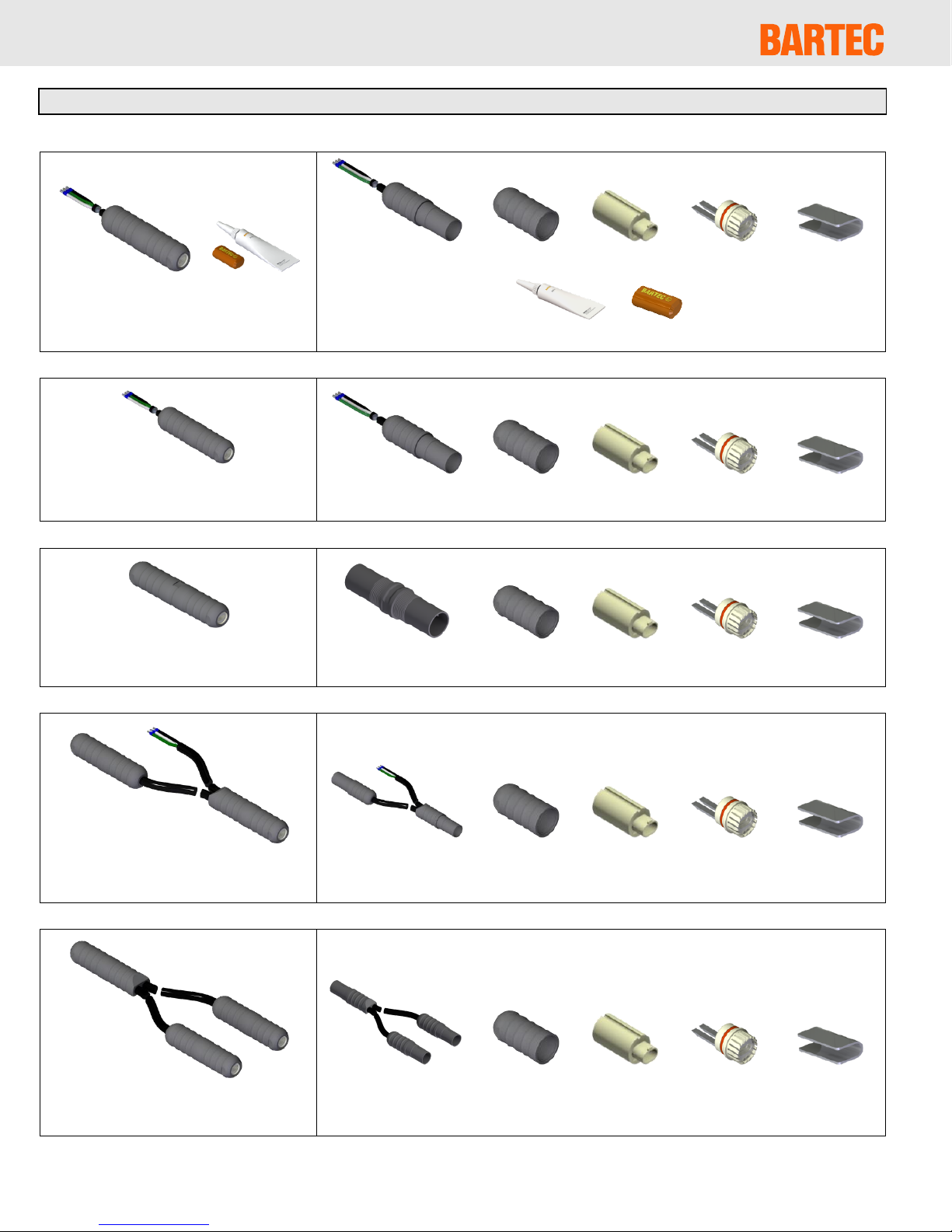
TWISTO/N-B is a family of connection kits for self-regulating trace heat-
ers. The TWISTO/N-B connection kits are simple and safe to use, yet
faster to install and more cost effective than conventional systems. They
can be used with BARTEC BACAB FT trace heaters in fixed equipment
heating systems for multiple applications (e.g. heating of pipes, roof and
gutter de-icing etc.).
Certifications / Approvals
TWISTO/N-B Connection for self-regulating trace heater for roof and
gutter de-icing, pipe applications etc.; for use with BARTEC BACAB FT
trace heater only
Technical data
Operating voltage
max. 250 VAC
Current
max. 16 A
Ambient
temperature range
-40 °F to 185 °F / -40 °C to 85° C
Operation
temperature range
-40 °F to 150 °F / -40 °C to 65 °C
Protection class
NEMA Type 4X / IP66
The following terms describe the parts of the trace heater within these
instructions:
Safety
For safe installation and operation of the TWISTO/N-B the technical
requirements and instructions given in this manual must be followed.
WARNING
Risk of fire or electrical shock. Follow these guidelines to avoid per-
sonal injury or material damage.
All electrical systems and installations must comply with BARTEC
GmbH requirements and be installed in accordance with the relevant
electrical codes and any other applicable national and local codes.
BARTEC GmbH, the US and Canadian electrical codes require
ground fault protection to be provided for all trace heating circuits.
Install the connection kit and trace heaters carefully.
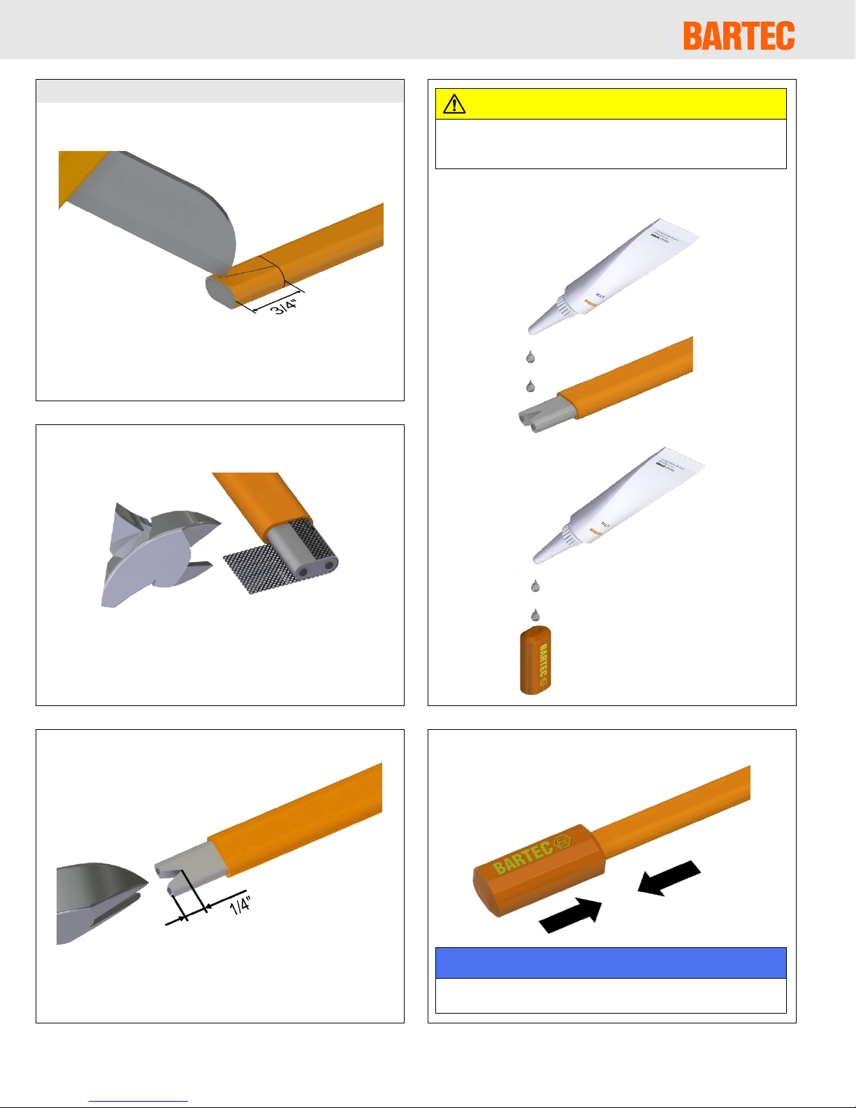
The bending radius of the trace heater must be at least 1″(25 mm).
Do not bend on the narrow axis.
Use the trace heaters and connection kit in accordance with the
intended purpose and strictly comply with the operational data speci-
fied in section Technical Data.
For roof and gutter applications use only the UV-resistant
FT 15 ‘black’ trace heater (certified by the –WS mark on the device).
Any defective component in a set must be replaced before installa-
tion.
Keep all components and the trace heaters dry before and during
installation.
To avoid short circuits, do not connect the trace heater bus wires
together.
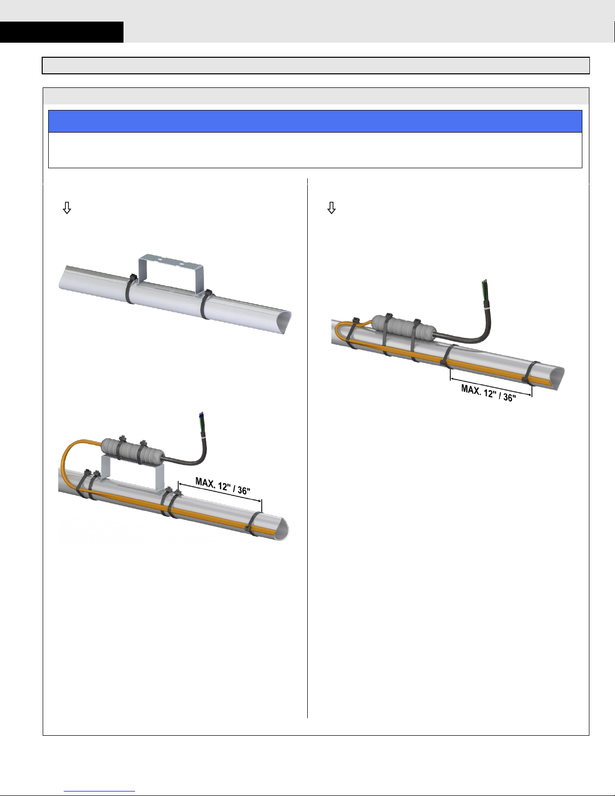
When used for roof and gutter de-icing, the TWISTO/N-B connection
kit must be installed in a dry place outside the gutter.
This kit contains silicone adhesive. Keep out of reach of children.
Store at below 77 °F (25 °C). Follow the safety instructions given on
the packaging.
Keep these instructions for future reference. If applicable, leave them
with the end user.
De-energize before installation or servicing.
Use only original BARTEC accessories.
bus wire
heating element
insulation jacket
grounding braid
outer jacket

21-56N0-7N0001/392164
Reservation Technical data subject to change without notice.
No claims for damages arising from alternations, errors or misprints shall be allowed.
Page 3 / 20
Kit contents
The following table lists the kit contents for each of the TWISTO/N-B connection systems:
TWISTO/N-B-PK
Power connection with end seal
1 x
1 x
1 x
1 x
1 x
1 x
1 x
TWISTO/N-B-P
Power connection
1 x
1 x
1 x
1 x
1 x
TWISTO/N-B-S
Splice connection kit
1 x
2 x
2 x
2 x
2 x
TWISTO/N-B-PS
Powered splice kit
1 x
2 x
2 x
2 x
2 x
TWISTO/N-B-T
T-Connection kit
1 x
3 x
3 x
3 x
3 x

Installation Instructions
TWISTO/N-B
21-56N0-7N0001/392164
Reservation Technical data subject to change without notice.
No claims for damages arising from alternations, errors or misprints shall be allowed.
Page 4 / 20
TWISTO/N-B-PT
Powered T-Connection kit
1 x
3 x
3 x
3 x
3 x
TWISTO/N-B-X
X-Connection kit
1 x
4 x
4 x
4 x
4 x
SILICONE END SEAL (5X)
1 x
5 x
Component identification
Threaded Cap
End cap
Powered splice
assembly
Sleeve
Silicone
adhesive
T-Assembly
Clamping
sleeve
Splice assem-
bly
Powered T-
Assembly
Clamping
sheet
Power connec-
tion assembly
X-Assembly

21-56N0-7N0001/392164
Reservation Technical data subject to change without notice.
No claims for damages arising from alternations, errors or misprints shall be allowed.
Page 5 / 20
Installation
Required tools / equipment
The following tools and equipment are required for installation of the
TWISTO/N-B connection kits:
Wire cutters
Utility knife
Tape measure
Cautions and warnings
WARNING
Risk of fire or electrical shock. De-energize all power circuits before
installation or servicing. Always use ground fault equipment within
the heat tracing system.
Double-check that all power circuits are de-energized before you
begin your work.
Make sure that you do not exceed the maximum heating circuit
length for the trace heater type you use. Refer to the design
guide of the heating system.
Preparation of the trace heater
WARNING
Risk of short cuts and/or material damage. Keep the trace heater
ends dry before and during installation. Observe the trace heater’s
installation instructions.
Unroll the required trace heater in a straight line and cut to the
correct length. Cut off the trace heater ensuring a straight cut.
Slide on the threaded cap and the clamping sleeve.
Remove 1 5/8″(42 mm) of the outer jacket from the end of the
trace heater.
Slide the clamping sheet over the grounding braid right up to the
outer jacket.
Draw the grounding braid back over the clamping sheet.
Make sure that the clamping sleeve’s orientation is correct in order
that the blades fit into the designated slots.
Insert the trace heater into the sleeve until the trace heater is
flush with the sleeve.
1
4
5
6
2
3

Installation Instructions
TWISTO/N-B
21-56N0-7N0001/392164
Reservation Technical data subject to change without notice.
No claims for damages arising from alternations, errors or misprints shall be allowed.
Page 6 / 20
Connection of the trace heater
Make sure that the tip of the assembly and the groove of the
clamping sleeve are properly aligned.
Push the clamping sleeve against the sleeve and insert into the
assembly.
Power connection, powered splice, T-, powered T and
X-connection kits:
Splice kits:
Completely screw together the threaded cap and the assembly.
WARNING
Risk of fire or malfunction. Double-check that there is no gap left
between the threaded cap and the assembly.
If applicable, repeat steps 3 to 8 to connect all remaining trace
heaters:
Splice kit:
Powered splice kit:
T-Connection kit:
Powered T-Connection kit:
X-Connection kit:
7
8
9

21-56N0-7N0001/392164
Reservation Technical data subject to change without notice.
No claims for damages arising from alternations, errors or misprints shall be allowed.
Page 7 / 20
Installation of the end seal
Cut the trace heater off straight.
Remove 3/4″(20 mm) of the outer jacket.
Remove the exposed grounding braid. Make sure that the
insulation jacket is not damaged.
Cut in a triangle (1/4″/ 5 mm) between the bus wires.
CAUTION
The silicone adhesive may cause irritation to skin and eyes. Avoid
eye contact. Avoid repeated or prolonged skin contact. In case of
contact with eyes, rinse with water and seek medical advice.
Put silicone adhesive onto the exposed insulating jacket and into the
end cap.
Push the end cap over the end of the trace heater.
NOTICE
Allow the adhesive to cure for 20 minutes, then visually inspect. Full
strength is reached after 24 hours.
10
14
13
12
11

Installation Instructions
TWISTO/N-B
21-56N0-7N0001/392164
Reservation Technical data subject to change without notice.
No claims for damages arising from alternations, errors or misprints shall be allowed.
Page 8 / 20
Attachment to pipes
Attachment methods
NOTICE
It is recommended to install the TWISTO/N-B connection kit on a mounting bracket (“off-pipe”) to protect it from excessive temperatures (as shown
on the left). However, when used in moderate temperature conditions all TWISTO/N-B connection kits can also be directly attached to the pipe (as
shown on the right).
Off-pipe installation:
Attach the mounting bracket (see section Accessories on page 10)
to the pipe using cable ties.
Attach the TWISTO/N-B connection kit to the mounting bracket and
the trace heater to the pipe using polyester tape or cable ties.
Make sure that the distance between 2 attachment points does not
exceed 12″(300 mm) on plastic pipes or 36″(900 mm) on steel
pipes.
On-pipe installation:
Attach the trace heater and the TWISTO/N-B connection kit to the pipe
using polyester tape or cable ties.
Make sure that the distance between 2 attachment points does not
exceed 12″(300 mm) on plastic pipes or 36″(900 mm) on steel pipes.
1A
1B

21-56N0-7N0001/392164
Reservation Technical data subject to change without notice.
No claims for damages arising from alternations, errors or misprints shall be allowed.
Page 9 / 20
Position on the pipe
Depending on the TWISTO/N-B kit you use, the position on the
pipe is as follows (note that all TWISTO/N-B connection kits can be
installed on a mounting bracket (“off-pipe”) or directly on the pipe):
Power connection:
T-Connection:
Splice:
Powered T-Connection:
Powered splice:
X-Connection:
2

Installation Instructions
TWISTO/N-B
21-56N0-7N0001/392164
Reservation Technical data subject to change without notice.
No claims for damages arising from alternations, errors or misprints shall be allowed.
Page 10 / 20
Accessories
The following original BARTEC accessories are available for the TWISTO/N-B. Where required, additional installation instructions are included.
NOTICE
To ensure compliance with the existing technical regulations, use only original accessories from BARTEC. The use of original accessories from BAR-
TEC is a precondition for the consideration of any claims under warranty.
Adhesive tapes
for trace heater installation on pipes etc.
Catalog No.:
PT-164 (100706)
(for up to 212 °F / 100 °C)
GT-108 (392328)
(for up to 356 °F / 180 °C)
.
Cable ties
for trace heater installation on pipes etc.
Catalog No.:
CT-200 (126225)
(length: 8″/ 200 mm;
for up to 221 °F / 105 °C;
1000 pieces)
Mounting bracket
for off-pipe installation
Catalog No.:
MB-1 (200514)

Table des matières
Vue générale 11
Certifications / Homologations 12
Caractéristiques techniques 12
Sécurité 12
Contenu des kits 13
Identification des composants 14
Installation 15
Outils / Equipement requis 15
Avertissements et mises en garde 15
Préparation du câble chauffant 15
Raccordement du câble chauffant 16
Pose de l’embout d’étanchéité 17
Fixation sur une tuyauterie 18
Méthodes de fixation 18
Positionnement sur la tuyauterie 19
Accessoires 20

Consignes d’installation
TWISTO/N-B
21-56N0-7N0001/392164
Restrictions Sous réserve de modifications techniques. Les modifications, défauts et erreurs
d’impression ne pourront en aucun cas faire l’objet de revendications de dommages et intérêts.
Page 12 / 20
Vue générale
TWISTO/N-B est une gamme de kits de raccordement destinés aux
câbles chauffants autorégulants. Les kits de raccordement TWISTO/N-B
sont simples d’utilisation et sûrs. De plus, leur pose est plus rapide et ils
sont plus rentables que les systèmes de raccordement classiques.
Ils peuvent être utilisés avec les câbles chauffants de type BARTEC
BACAB FT des systèmes fixes de traçage par résistance utilisés pour
diverses applications (par ex. chauffage de tuyauteries, protection de
toitures et gouttières contre le gel, etc.).
Certifications / Homologations
Raccordement TWISTO/N-B pour câble chauffant autorégulant destiné
à la protection antigel des toitures et gouttières, au chauffage de tuyau-
teries, etc. ; à utiliser uniquement avec les câble chauffants de type
BARTEC BACAB FT
Caractéristiques techniques
Tension de service
max. 250 VAC
Courant
max. 16 A
Plage de
température ambiante
-40 °F à 185 °F / -40 °C à 85 °C
Plage de
température de service
-40 °F à 150 °F / -40 °C à 65 °C
Classe de protection
NEMA Type 4X / IP66
Voici les termes employés dans les présentes consignes pour désigner
les différents éléments qui composent le câble chauffant :
Sécurité
Afin de garantir la sécurité lors de l’installation et de l’utilisation du
TWISTO/N-B, il est impératif de respecter les exigences ainsi que les
consignes techniques mentionnées dans le présent manuel.
AVERTISSEMENT
Risque d’incendie ou d’électrocution. Suivez ces consignes pour éviter
toute blessure ou dommage matériel.
Tous les systèmes et installations électriques doivent satisfaire aux
exigences imposées par la BARTEC GmbH et doivent être installés
conformément aux normes électriques en vigueur ainsi qu’aux autres
prescriptions nationales et locales applicables.
La BARTEC GmbH ainsi que les normes électriques américaines et
canadiennes imposent une protection contre les défauts à la terre
pour tous les circuits de traçage électrique.
La pose du kit de raccordement et des câbles chauffants doit être
réalisée avec soin.
Le rayon de courbure du câble chauffant ne doit pas être inférieur à
1″(25 mm). Ne pas courber le câble chauffant sur la tranche.
Utilisez les câbles chauffants et le kit de raccordement adaptés à
l’usage prévu et répondant aux caractéristiques de fonctionnement
spécifiées à la section Caractéristiques techniques.
Pour une utilisation sur des toitures ou gouttières, utiliser exclusive-
ment le câble chauffant FT 15 'black', résistant aux UV (certifié par la
mention –WS apposée sur l’équipement).
Tout élément défectueux dans le kit doit être remplacé avant l’installation.
Conservez tous les éléments et les câbles chauffants au sec avant et
pendant l’installation.
Pour éviter un court-circuit, ne jamais raccorder ensemble les deux
conducteurs du câble chauffant.
Pour le traçage électrique de toitures ou gouttières, le kit de raccordement
TWISTO/N-B doit être installé à un emplacement sec, hors de la gouttière.
Ce kit contient de la colle au silicone. Tenir hors de portée des en-
fants. Conserver à une température inférieure à 77 °F (25 °C). Res-
pectez les consignes de sécurité indiquées sur l’emballage.
Conservez ces instructions pour un usage ultérieur. Le cas échéant,
remettez-les à l’utilisateur final.
Coupez l’alimentation électrique avant toute installation ou opération
de maintenance.
Utilisez exclusivement des pièces et accessoires d’origine BARTEC.
conducteur
élément chauffant
gaine isolante
tresse de mise à la terre
surgaine

21-56N0-7N0001/392164
Restrictions Sous réserve de modifications techniques. Les modifications, défauts et erreurs
d’impression ne pourront en aucun cas faire l’objet de revendications de dommages et intérêts.
Page 13 / 20
Contenu des kits
Le tableau ci-dessous répertorie le contenu de chaque kit des différents systèmes de raccordement TWISTO/N-B :
TWISTO/N-B-PK
Raccordement électrique et
embout d’étanchéité
1 x
1 x
1 x
1 x
1 x
1 x
1 x
TWISTO/N-B-P
Raccordement électrique
1 x
1 x
1 x
1 x
1 x
TWISTO/N-B-S
Kit de jonction
1 x
2 x
2 x
2 x
2 x
TWISTO/N-B-PS
Kit de jonction avec alimentation
1 x
2 x
2 x
2 x
2 x
TWISTO/N-B-T
Kit de raccordement en T
1 x
3 x
3 x
3 x
3 x

Consignes d‘installation
TWISTO/N-B
21-56N0-7N0001/392164
Restrictions Sous réserve de modifications techniques. Les modifications, défauts et erreurs
d’impression ne pourront en aucun cas faire l’objet de revendications de dommages et intérêts.
Page 14 / 20
TWISTO/N-B-PT
Kit de raccordement en T avec alimentation
1 x
3 x
3 x
3 x
3 x
TWISTO/N-B-X
Kit de raccordement en X
1 x
4 x
4 x
4 x
4 x
EMBOUT D’ÉTANCHÉITÉ EN SILICONE (5X)
1 x
5 x
Identification des composants
Capuchon
fileté
Bouchon
d’extrémité
Raccord de
jonction ali-
menté
Manchon
Colle silicone
Raccord en T
Douille
d’attache
Raccord de
jonction
Raccord en T
alimenté
Agrafe de
serrage
Raccord
d’alimentation
Raccord en X

21-56N0-7N0001/392164
Restrictions Sous réserve de modifications techniques. Les modifications, défauts et erreurs
d’impression ne pourront en aucun cas faire l’objet de revendications de dommages et intérêts.
Page 15 / 20
Installation
Outils / Equipement requis
Pour le montage des kits de raccordement TWISTO/N-B, vous aurez
besoin des outils et équipements suivants :
Pince coupante
Couteau à dégainer
Mètre-ruban
Avertissements et mises en garde
AVERTISSEMENT
Risque d’incendie ou d’électrocution. Mettre tous les circuits élec-
triques hors tension avant toute installation ou opération de main-
tenance. Toujours utiliser un dispositif de protection contre les
défauts à la terre au sein du système de traçage électrique.
Vérifiez bien que tous les circuits électriques sont hors tension
avant de débuter votre travail.
Veillez à ne pas dépasser la longueur de circuit de traçage maxi-
male autorisée pour le type de câble chauffant utilisé. Consultez
à ce sujet le guide de conception du système de traçage.
Préparation du câble chauffant
AVERTISSEMENT
Risque de court-circuit et/ou de dommages matériels. Conservez les
extrémités du câble chauffant au sec avant et pendant toute la durée de
l’installation. Respectez les consignes d’installation du câble chauffant.
Déroulez le câble chauffant dans le prolongement de la bobine et
coupez-le à la longueur souhaitée. Sectionnez le câble chauffant
par une coupe droite.
Enfilez le capuchon fileté et la douille d’attache.
Supprimez la surgaine du câble chauffant sur 1 5/8″(42 mm).
Enfilez l’agrafe de serrage par-dessus la tresse métallique jusqu’au
ras de la surgaine.
Retournez la tresse métallique par-dessus l’agrafe de serrage.
Assurez-vous que la douille d’attache est correctement positionnée :
ses ergots doivent être alignés sur les orifices prévus à cet effet.
Introduisez le câble chauffant dans la douille jusqu’à ce qu’il
arrive au ras de cette dernière.
1
2
5
6
4
3

Consignes d‘installation
TWISTO/N-B
21-56N0-7N0001/392164
Restrictions Sous réserve de modifications techniques. Les modifications, défauts et erreurs
d’impression ne pourront en aucun cas faire l’objet de revendications de dommages et intérêts.
Page 16 / 20
Raccordement du câble chauffant
Assurez-vous que l’ergot du raccord et la rainure de la douille
d’attache sont correctement alignés.
Poussez la douille d’attache contre le manchon et insérez-la dans
le raccord.
Kits d’alimentation, de jonction avec alimentation, de raccordement en
T, de raccordement en T avec alimentation et de raccordement en X :
Kits de jonction :
Vissez ensemble le capuchon fileté et le raccord jusqu’en butée.
AVERTISSEMENT
Risque d’incendie ou de dysfonctionnement. Assurez-vous qu’il n’y
a aucun espace entre le capuchon fileté et le raccord.
Le cas échéant, répétez les étapes 3 à 8 pour raccorder tous les
câbles chauffants restants :
Kit de junction :
Kit de jonction avec alimentation :
Kit de raccordement en T :
Kit de raccordement en T avec alimentation :
Kit de raccordement en X :
8
7
9

21-56N0-7N0001/392164
Restrictions Sous réserve de modifications techniques. Les modifications, défauts et erreurs
d’impression ne pourront en aucun cas faire l’objet de revendications de dommages et intérêts.
Page 17 / 20
Pose de l’embout d’étanchéité
Sectionnez le câble chauffant par une coupe droite.
Retirez la surgaine sur 3/4″(20 mm).
Enlevez la tresse métallique ainsi dénudée. Veillez à ne pas
endommager la gaine isolante.
Faites une entaille triangulaire (1/4″/ 5 mm) entre les conducteurs.
ATTENTION
La colle à la silicone peut irriter la peau et les yeux. Evitez tout
contact avec les yeux. Evitez tout contact répété ou prolongé avec
la peau. En cas de contact avec les yeux, rincez à l’eau et consultez
un médecin.
Appliquez de la colle silicone sur la partie dénudée de la gaine
isolante et dans le bouchon d’extrémité.
Enfilez le bouchon sur l’extrémité du câble chauffant.
AVIS
Laissez sécher la colle 20 minutes avant de procéder à une inspec-
tion visuelle. La résistance totale sera atteinte après 24 heures.
10
13
12
11
14

Consignes d’installation
TWISTO/N-B
21-56N0-7N0001/392164
Restrictions Sous réserve de modifications techniques. Les modifications, défauts et erreurs
d’impression ne pourront en aucun cas faire l’objet de revendications de dommages et intérêts.
Page 18 / 20
Fixation sur une tuyauterie
Méthodes de fixation
AVIS
Il est recommandé d’installer le kit de raccordement TWISTO/N-B sur un étrier de fixation (installation « off-pipe ») afin de le protéger des tempéra-
tures excessives (comme illustré à gauche). Toutefois, si les températures d’utilisation prévues restent modérées, tous les kits de raccordement
TWISTO/N-B peuvent être directement fixés sur la tuyauterie (comme illustré à droite).
Installation « off-pipe » :
Fixez l’étrier de fixation (voir la section Accessoires, page 20) à la
tuyauterie à l’aide de serre-câbles.
Fixez le kit de raccordement TWISTO/N-B à l’étrier de fixation et le
câble chauffant à la tuyauterie à l’aide de ruban adhésif polyester
ou de serre-câbles.
Veillez à ne pas dépasser 12″(300 mm) entre deux points de
fixation sur une tuyauterie en plastique et 36″(900 mm) sur une
tuyauterie en acier.
Installation « on-pipe » (au contact direct de la tuyauterie) :
Fixez le câble chauffant et le kit de raccordement TWISTO/N-B à la
tuyauterie à l’aide de ruban adhésif polyester ou de serre-câbles.
Veillez à ne pas dépasser 12″(300 mm) entre deux points de fixation
sur une tuyauterie en plastique et 36″(900 mm) sur une tuyauterie en
acier.
1A
1B
This manual suits for next models
7
Table of contents
Languages:
Other Bartec Cables And Connectors manuals
Popular Cables And Connectors manuals by other brands

Panasonic
Panasonic P5K Operation manual

Panasonic
Panasonic Mini USB Connectors AXJ4 Specifications

NetComm
NetComm POE20 Specifications

OBSIDIAN CONTROL SYSTEMS
OBSIDIAN CONTROL SYSTEMS Netron RDM10 installation guide

Monster
Monster SIRIUS ANTENNA EXTENSION CABLE user guide

Real Cable
Real Cable HDD18 operating manual