11-8865-7D0001_A-03/2019-288307
DTL III Ex Type 17-8865-4.22/2200 3000 Operating manual
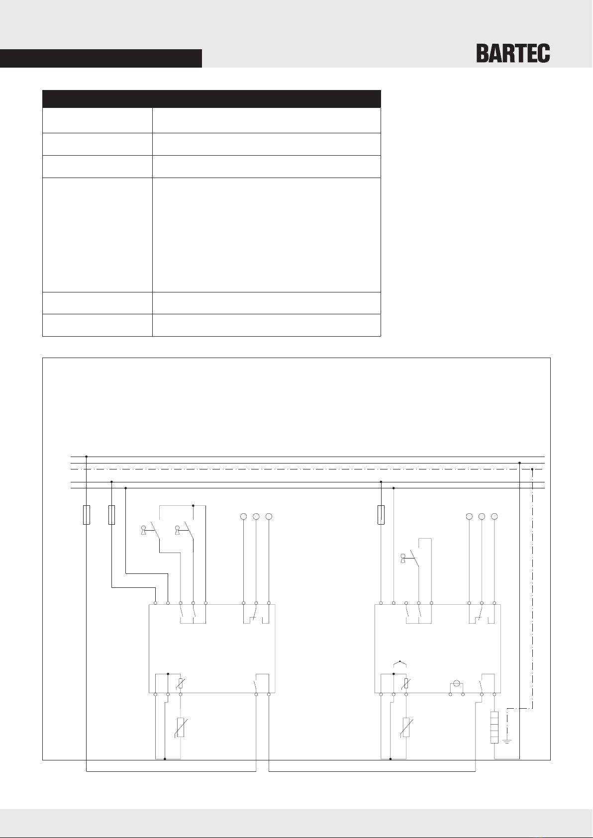
4.2. Installation
The device must be connected in accordance with the wiring diagram with due consideration to
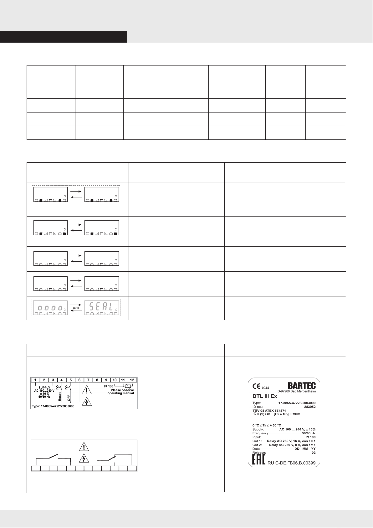
thecurrent/voltagespecications.Itisessentialtoobservethespecicationsonthetypelabel.
If the resistance thermometer that is connected to the device is brought into Dust Ex areas, it must
be ensured that it has the appropriate approval.
In principle, the resistance thermometer must be mechanically and temperature-stably attached to the
point to be measured in order to ensure reliable thermal coupling. This should be carried out by using
temperature-resistant aluminium adhesive tape or similar materials.
All output circuits connected to the device must be protected by suitable over current protection
devices (e.g. CB).
4.3. Commissioning
The device may only be operated in a clean and undamaged condition. In case of visible damage, the device
must be deactivated and appropriate repair actions initiated.
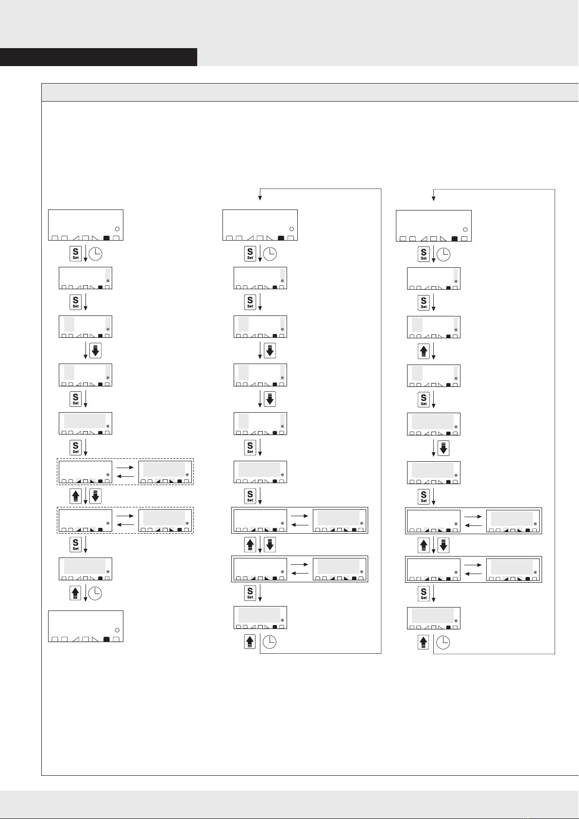
Commissioning must be carried out in the following steps:
Connect the device to electric power
Set the limiter alarm setpoint and the pre-alarm setpoint that suits the application.
Set the access password for the system parameters (incl. the setpoint for the limiter alarm).
If required, set the password for resetting the limiter alarms
Note: When controlling Ex heating circuits, the access password for the setpoint limit alarm and the
password for resetting limiter alarms must be set, since the setting of the DTL III Ex in accordance with
EN 60079-7 or EN 60079-30-1 must be “secured” and “sealed” for interaction with explosion-protected
heating circuits.
With the DTL III Ex, this is achieved by using separate passwords for
- Resetting limiter alarms
- Setting the set point Limiter alarm
4. Assembly, installation and commissioning3. Safety instructions
Before commissioning, please check the
marking on the DTL III Ex for suitability for
the intended use.
For electrical systems, the relevant installation
and operating regulations as well as other
relevant national regulations must be observed.
The operator of an electrical system in a
hazardous environment must keep the
equipment in good condition, operate and
monitor it properly and do maintenance and
repairs.
All generally valid statutory rules and the other
binding directives on safety at work, accident
prevention and the protection of the
environment must be adhered to.
When using the DTL III Ex to monitor the
temperatures of the heating and heating
circuits in hazardous areas, the following
points must be observed:
- The factory setting of the limiter alarm
setpoint is 190 °C (in Temperature
Class T3). If the application requires another
limit value, this must be set.
- The limiter alarm setpoint setting must be
protected by a password that is accessible
only to authorised people. The factory
setting of the PAS.2 password (“OFF“) must
be altered.
- The resetting of limiter alarms can be
protected by a password, whereby the
factory setting of the PAS.1 password
(“OFF“) must be changed.
- The remote reset use (e.g. by using a
key switch) may only be made possible
to authorised people.
- During commissioning a test of correct
functioning must be conducted in
accordance with EN 60079-30-2.
- The functionality of the DTL III Ex must
be checked in accordance with the
speciedtestintervalsoftheIndustrial
Safety Regulation.
4.1. Assembly
ThedetailsonthetypelabelandintheECTypeExaminationCerticatemustbeobserved.Thecontroller
isttedintoaDINenclosure with 4 HP (horizontal pitch). The device can be latched onto a mounting rail in
any mounting position in a row.
Inprinciple,itmustbeensuredthatthedeviceisproperlyventilatedtoensurethatthespeciedoperating
temperature limits are not exceeded. Avoid use in areas with additional heat sources so that the permissible
ambient temperature of the limiter is not exceeded.
The device must be installed as far away as possible from sources that could cause strong electromagnetic
interference (e.g. from motors).
Whenconnectingstrandedorne-strandedconductors,theconductorendsmustbeadequatelyprepared.
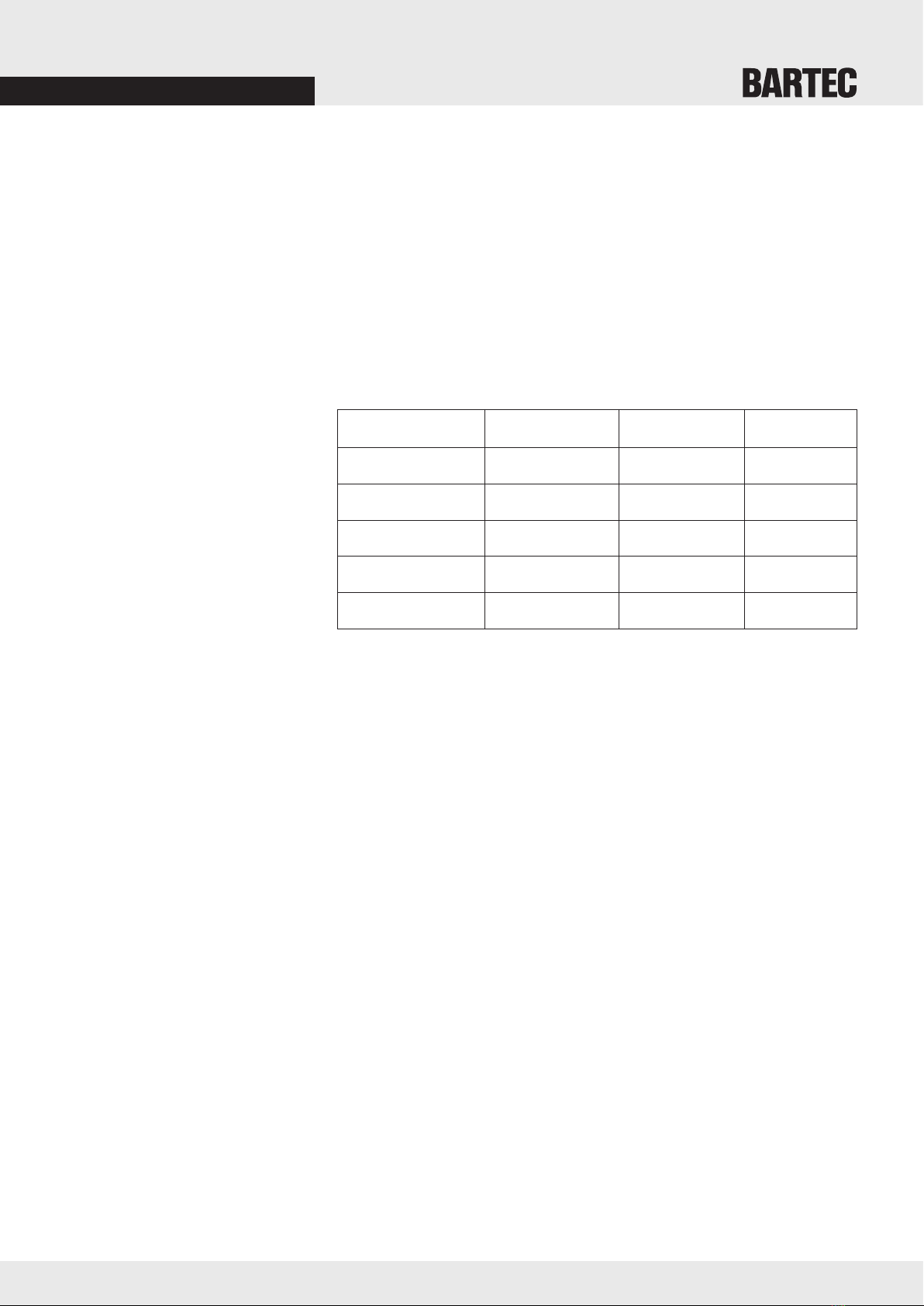
Assembly instructions for assigning the connection terminals
Conductor Min. Max. Minimum length
cross-section cross-section wire end ferrule
rigid 0.2 mm² 2.5 mm²
with wire end ferrule 0.25 mm² 2.5 mm² 10 mm
2 conductors rigid 0.2 mm² 0.75 mm²
2 conductors with
non-insulated wire end ferrule 0.2 mm² 0.75 mm² 10 mm
2 conductors with
TWIN wire end ferrule 0.5 mm² 1.5 mm² 10 mm
EN 5/12