Bartell Global DFG280 User manual

DFG280
OWNER’S MANUAL
DFG280
Operating Manual
V1.05
2
WWW.BARTELLGLOBAL.COM
Bartell Morrison Inc.
170 Traders Boulevard East
Mississauga, Ontario, Canada
L4Z 1W7
Tel: (647) 953-4100
Fax: (647) 953-4101
Bartell Morrison USA LLC
200 Commerce Drive, Unit A
Freehold, NJ, USA
07728
Tel: (848) 225-8100
Fax: (848) 225-8101
SPE International Ltd.
Honeyholes Lane
Dunholme, Lincoln, England
LN2 3SU
Tel: 01673 860709
Fax: 01673 861119
Innovatech
4701 Allmond Ave
Louisville, Kentucky, USA
40209
Tel: (425) 405-9100
Fax: (425) 405-9101

DFG280
Operating Manual
V1.05
3
This manual is provided to persons purchasing an SPE machine and may not be
reproduced in part or full without written permission of SPE International Ltd.
This manual provides the basic information required and is only to be used as a guideline.
The SPE machines are manufactured and covered by SPE design registrations granted and
pending.
SPE International Ltd reserves the right to alter the equipment design and specification as
required without notice.

DFG280
Operating Manual
V1.05
4
INDEX
Page No
5
Safety
6
Safety Precautions
7
Operating Manual
8
Starting Work
9
General Operation
10 Changing the Grinding Head
11 Electrical Instructions
12 Maintenance
13-18 Spare Parts Breakdown
19-21 Wiring Diagrams
22 Electrical Requirements
23-24 Noise and Vibration Assessment
26 Warranty
27 Declaration of Conformity
28
Conditions of Sale

DFG280
Operating Manual
V1.05
5
SAFETY
Only trained operatives should be allowed to work the DFG280 floor grinder.
All operatives should wear ear defenders, goggles and an effective dust mask. Note: It is
possible that the noise level produced by the DFG280 could exceed 90dbA. Personal noise
protection must be worn and the equipment must be used in line with guidelines laid down
by the Health & Safety Executive.
Never leave the DFG280 unattended whilst in use. Always stop the motor prior to leaving
the machine.
Keep the electric lead away from the grinding head.
Always use the correct voltage for the machine and RCD protection.
Always ensure that all power leads are disconnected before attempting to service the
machine. The service of electrical components should be carried out by authorised
personnel. Never tip the machine completely backwards until the grinding plates have
stopped rotating, just raise slightly.
Vibration will occur at various levels dependent on the attachments and work being
completed. It is recommended that tests are taken on site to provide the operator with
accurate information on using the equipment within the guidelines laid down by the Health &
Safety Executive.
Never operate the machine without a dust skirt.
NOTE:
NEVER OPERATE THE COMPACT FLOOR GRINDER IN WET CONDITIONS AS
ELECTRICAL COMPONENTS ARE NOT WATERPROOF

DFG280
Operating Manual
V1.05
6
SAFETY PRECAUTIONS
DANGER
EXPLOSION HAZARD
Never operate the machine in an explosive
atmosphere, near combustible materials, or where
ventilation does not clear exhaust fumes.
WARNING
BURN HAZARD
Never come into contact with the engine or muffler
when engine is operating or shortly after it is turned
off. Serious burns may occur.
CAUTION
MOVING PARTS
Before starting the machine, ensure that all guards
and safety devices are in place and functioning
properly.
ATTENTION
READ OWNER’S MANUAL
Read and understand owner’s manual before using
this machine. Failure to follow operating
instructions could result in serious injury or death.

DFG280
Operating Manual
V1.05
7
DFG280 OPERATING MANUAL
This manual covers, to the best of our knowledge, the operation and maintenance of the
DFG280. Before operation of the equipment the manual should be read and understood by the
operator. The safety regulations must be followed at all times. Service of electrical
components should be carried out by authorised personnel. Failure to follow these instructions
could result in damage to the machine and/or serious personal injury or death.
WARNING
Failure to follow these instructions may result in serious personal injury or death. SPE
disclaims all responsibility for damage to persons or objects arising as a consequence of
incorrect handling of the machine and failure to inspect the machine for damage or other faults
that may influence the operation prior to starting work.

DFG280
Operating Manual
V1.05
8
STARTING WORK
Check the following prior to starting the equipment.
•Check all nuts and bolts for tightness
•Check the plugs and cables for damage
1.
The machine is fitted with an adjustable handle which can be folded over for ease of
lifting and transportation. The handle can be adjusted by releasing the two locking pins on
the side and moving the handle into one of three positions for preferred operator comfort.
This is then locked in place by re-engaging the locking pins.
2.
Fit a suitable grinding head by tilting the machine backwards on to its handle. The
machine must be secured and supported. Attach the grinding head to the machine using the
four countersunk fixing screws and tighten. Lower the machine back to the upright position.
3.
Connect the vacuum hose to the dust extraction port, if a dust control vacuum is being
used. We recommend the SPE VAC316 3 motor vacuum for dust control.
4.
Ensure that the power supply is correct for the machine (see page 11 for further details).
Connect the machine to the power supply.
5.
To start the machine
•Check that the stop button is out by rotating clockwise.
•Lift the grinding head slightly by tipping the machine onto its rear wheels.
•Press the start button.
•Lower the machine onto the floor, moving the head evenly across the surface to
ensure a smooth ground finish.
6.
To stop the machine, push the red stop button.
7.
The machine is also fitted with two removable panels in the dust shroud which can assist
with edge work. Undo the two thumb nuts and remove the panel to allow the grinding head
to get closer to the vertical surface. Once done, replace the panel and refit and tighten the
two thumb nuts.
Never allow the machine to stop moving whilst grinding head is in contact with the
surface.

DFG280
Operating Manual
V1.05
9
GENERAL OPERATION
Although excessive downward pressure on the cutters may marginally improve the work
rate/finish this would increase the wear rates on the head, components and could result in
overloading the motor.
Tests have shown that two light passes are quicker and more cost effective than one slow
heavy pass and have conclusively shown that heavy downward pressure reduces the life of
the tooling discs used.
The DFG280 is normally operated in a forwards and left to right direction, the operator
varying the speed of travel to determine the final finish. It is permissible to operate the
machine with a backwards and forwards action. Each pass should be overlapped to
produce a uniform finish.

DFG280
Operating Manual
V1.05
10
CHANGING THE GRINDING HEAD
1.
Disconnect from the power supply.
2.
Tilt the machine backwards on to its handle. The machine must be secured and
supported.
3.
Make sure the grinding head is cool to the touch.
4.
Use a hex key to undo the countersunk screws securing the Grinding Head to the adaptor
plate.
5.
Remove the grinding head and replace.
6.
Ensure the grinding head is seated to the adaptor plate correctly prior to tightening the
countersunk screws diagonally.
7.
Lower the machine back to the upright position.
8.
Reconnect to the power supply.
CHECK FOR CORRECT WEAR RATE AFTER QUARTER OF AN HOUR AND AGAIN AT
HALF AN HOUR INTERVALS - THIS WILL GIVE AN IDEA OF WEAR RATE

DFG280
Operating Manual
V1.05
11
ELECTRICAL INSTRUCTIONS
The DFG280 machine is supplied with a specially commissioned 110V electric motor and
starter switch assembly. Each unit is fully tested and the safety overload relays have been
calibrated and set according to the manufacturers specifications. In the event of the malfunction
on a new machine the owner should first check that the power supply on site is suitable and
adequate.
DFG280-5 (110V)
•The 110V motor requires a 32 Amp supply.
•To avoid voltage drop the cable size must be a minimum of 4.0mm 3 core. Maximum
length of cable not to exceed 30 metres.
•If a transformer is used it must have a continuous rated output of at least 3 KVA. In
practice this means that a 5 KVA transformer must be used.
DFG280-1 (415V Three Phase)
DFG280-3 (230V Single Phase)
•The 230V/400V require a 16 Amp supply.
DFG280-6 (115V)
•The 115V motor requires a 15 Amp supply.
All cables should be fully uncoiled and never left wrapped around cable reels or tied in loops.
If the power is to be generated, the DFG280 requires a minimum 8kva generator.
The motor is protected with a safety trip in the panel. Should the trip be activated, it will reset
automatically after cooling down.
If the motor repeatedly cuts out then it will be damaged. The possible causes are
either an inadequate power supply, overloading of the machine, or an electrical fault.

DFG280
Operating Manual
V1.05
12
MAINTENANCE
Prior to any maintenance or adjustment disconnect the machine from the power supply.
AFTER USE:
-
Clean the machine to remove all build-up of dust and surface residue. If using a hose
pipe or pressure washer take care that water is not directed onto electrical components
and switches. (Note: Motors and switches are not waterproof)
-
All components should be checked daily for tightness.
-
Check the plugs and cables for damage.
-
The flexible drive coupling that support the grinding head should be checked on a
weekly basis.
-
Any excess vibration due to uneven head wear should result in the head being changed
to eliminate damage to coupling.
BASIC MAINTENANCE CHECKLIST
DAILY: (or every 8hrs to 10hrs)
•Check all nuts and bolts for tightness.
•Check the condition of the grinding head
•Check the plugs and cables
WEEKLY:
All the above with the following: -
•All of the above with the following.
•Check the flexible drive coupling
•Check the support wheels and grease
DFG280-5 (110V) DFG280-3 (230V)
ITEM
NO. SPENo DESCRIPTION QTY. ITEM
NO.
11
50
51
DFG280-1 (415V)
.
15
5365
Pivot Plate Packer
2
16
5366 Clamping Bar 4
17
5367
Electrical Box Plate
1
18
5368 End Cap 2
DFG280-6 (115V)
19 5369 End Cap (with hole) 1 ITEM SPENo DESCRIPTION QTY.
Head Screw
SPM1X1702P Enclosure Kit (Enclosure + Stop Button)
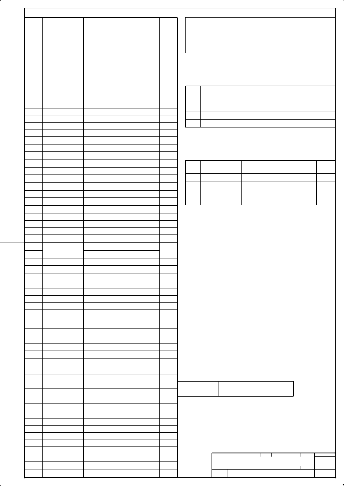
PARTS BREAKDOWN
DWG No.
DFG-280-A-(BOM)-0
SCALE
NOT TO SCALE
SHEET
1
of 6
SPENo DESCRIPTION QTY.
5360A
Motor (230V)
1
SPM1P1400 Switch 1
SPM1X14230
Under Voltage Coil
1
ITEM
NO.
SPENo DESCRIPTION
QTY
11 5360B Motor (415V) 1
47 SPCG/LNM25 Cable Gland 2
50
SPM1P065 Switch 1
51
SPM1X14400
Under Voltage Coil
1
20
5370
Roll Pin
2
NO.
21
5371 Bearing 4
4
5382
Connector
1
22 5372 Bearing Spacer 4
11
5360C
Motor (115V)
1
23 5373 Extraction Tube 1
50
SPM1P1800
Switch
1
24
5374 Flexi-Coupling 1
61
5381
Adapter Plate
1
25 5375 Retaining Screw 3
26
5376
Dust Skirt (580mm)
1
27
5377
Dust Skirt (140mm)
3
28
5378
Thumb Nut
4
29
5355 T-Mag Plate 1
30
5380
Handle Grip (Back)
2
31
Handle Grip (Front)
32
6013
Wheel (Rear)
2
33
7379 Locking Pin 2
34
9104
Handlebar Grip
2
35
BOLT022
M6x16 Hex Screw
6
36
BOLT042
M8x20 Hex Screw
2
37
BOLT043 M8x25 Hex Screw 4
38
BOLT045
M8x35 Hex Head Set Screw
4
39 BOLT166
M10 x 60 Socket Countersunk
2
40
BOLT268
M10x60 SOK Head Screw
2
41
BOLT305 M8x10 Cup Point Grub Screw 2
42
BOLT325
M10x30 Button Head Skt Screw
4
43
BOLT326 M10x35 Button Head Skt Screw 12
44
NUT043
M6 Nyloc Nut
3
45
NUT044 M8 Nyloc Nut 4
46
NUT045
M10 Nyloc Nut
10
47
SPCG/LNM20
Cable Gland EMC
1
48
SPM1Z1701P
Enclosure
1
49
SPM1Z1740P
Stop Button
1
50
SPM1P2500
Switch
1
51
SPM1X14110
Under Voltage Coil
1
52
TI/009
Tube Insert (Black)
2
53
WASHER003
M6 Plain Washer
9
54
WASHER004 M8 Plain Washer 12
55
WASHER005
M10 Plain Washer
14
56
WASHER005
M10 Plain Washer
8
57
WASHER009
M20 Plain Washer
2
58
WASHER023 M6 Spring Washer 6
59
WASHER024
M8 Spring Washer
6
60 WASHER052 M8x30 Repair Washer 2
1
5350
Main Body Plate
1
2
5351
Handle (Bottom Section)
1
3
5352 Handle (Top) 1
4
5353
Connector
1
5
5354 Adapter Plate 1
6
5356
Shroud
1
7
5357 Floating Shroud 1
8
(5358)
Shroud Edging
2
9
5359 Exhaust Bracket 1
10
5360
Motor (110V)
1
11
5361
Axle (Rear)
1
12
5362 Axle Sleeve 1
13
5363
Pivot Plate (10mm)
2
14
5364
Pivot Plate
2
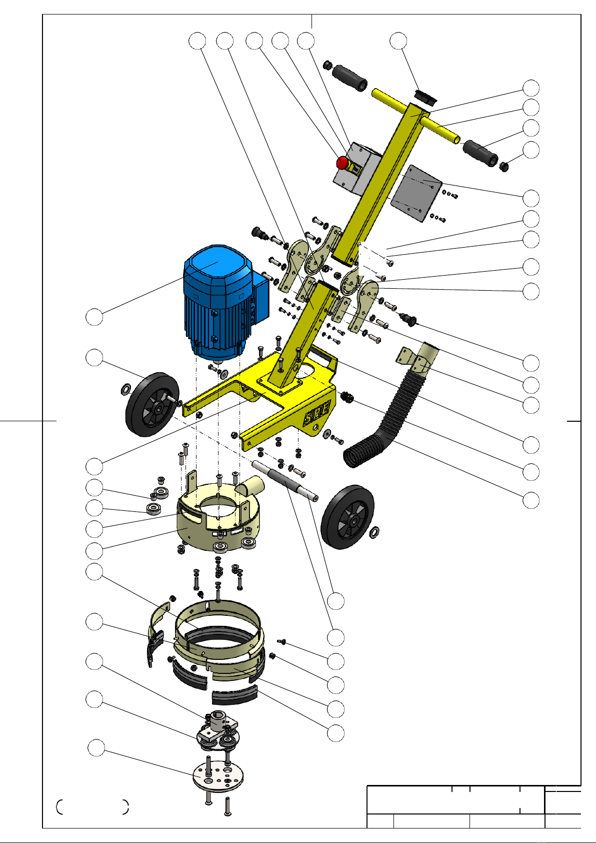
DFG280
.
2 19 49 50 48 18
3
3
34
(J.
52
17
16
14
20
13
10
y
32 y I
().
1
22
21
31
..
"
..
:,
'
e
d,
J,
, ,
I
I
I
.
I
.
y
I
11
11
I
'v
33
15
9
30
47
23
"'o
6
i-
I
d, d,
I
I
I
26
'------
7
4
.
I
I
.
!
"'
"'
11
12
'-------
25
28
24
8
27
5
Ass
P
e
A
m
R
b
T
ly
S
DWG No.
DFG-280-A-(ME)-1
I
SCALE
•
NOT TO SCALE
SHEET
2
of 6
I

I
I
'
°
I
7
"'-
G.--.
---
'
-
...
53 58 35
'y
56 42
"'-------._.._
"-
'-
"-'-
'
'
'
0-
0-
46 55 55 43
..
"-'-
'-----._
"
'
>--.
'-
"'-
0- 56 43
.
' '
.
'- '-
'
'-----._
0-
'-
'-
.
'
,
'-----._
-
. ,
"
"
y "·
37
54
54 "'-
"-,
'-
I
;,
y
I
y
I
y
I
I
I
45 jl
0
I
I
ll
I
I
0----._
'-
-y.
43
55
46
d:,
-
-
d:,
d, d,
d,
-y
- -
"'-------._
53 58 35
l
54
59
38
28
"'
-
I
I
..
I
d:,
!
.
I
.
,
1
I
I
.
I
.
d:,
"'-o
60 59 36
46 55 43
57
40
l
46
55
39
fDWG No.
I
I
l
r=
-
-
r
DFG280
) DFG-280-A-(ME)-2
I
FASTENERS
SHEET
3
of
6
-
25
NOT TO SCALE
I
SCALE
4
"
'
.

10
31
22 43
55
46
21
54
59
38
6
(DFG280-6 Only)
61
44 53 25
7
28
8
26
27
28 41
25
24
4
DFG280
DWG No.
DFG-280-A-(SA)-2
HEAD
SCALE NOT TO SCALE
SHEET
4
of 6

41 ADAPTER PLATE
(Standard Fitment)
46
55
24
55
40
5
39
DFG280
DWG No.
DFG-280-A-(SA)-3
COUPLING
SCALE NOT TO SCALE
SHEET
5
of 6

OPTIONAL TOOLING PLATES
SPENo.
DESCRIPTION
5355
T-Mag Plate
5381 Slide Mag Plate
T-MAG PLATE
SLIDE MAG PLATE
DWG No.
DFG-280-A-(OE)-4
TOOLING
SCALE
NOT TO SCALE
SHEET
6
of 6

DFG280
Operating Manual
V1.05
19
WIRING DIAGRAM
DFG280-1
DFG280-6

DFG280
Operating Manual
V1.05
20
WIRING DIAGRAM
DFG280-3
Table of contents
Other Bartell Global Construction Equipment manuals


Popular Construction Equipment manuals by other brands


Altrad
Altrad ATIKA RLC 40-10 Original instructions

Unimi Solutions
Unimi Solutions 1baseHPC installation manual

Skid Pro
Skid Pro QC605-SKD Setup instructions

Toro
Toro 22806 Operator's manual

Broderson
Broderson IC-35-2F Operating and maintenance manual

Epiroc
Epiroc HM Series Safety and operating instructions


