Epiroc HM Series Maintenance and service guide

HM 1500 F, 1500 M, 2000 F, 2000 M
Safety and operating instructions
Hydro Magnets
%
50
60
70
80
90
100
© Construction Tools GmbH | 3390 5149 01 | 2020-09-22
Original Instructions


Contents
© Construction Tools GmbH | 3390 5149 01 | 2020-09-22
Original Instructions
3
Table of Contents
1 Introduction ................................................................................................................................6
1.1 About these Safety and Operating Instructions...............................................................................................6
2 Safety instructions.....................................................................................................................7
2.1 Signal words........................................................................................................................................................7
2.2 Qualification ........................................................................................................................................................8
2.3 Intended use ........................................................................................................................................................8
2.3.1 Generator system ..............................................................................................................................................9
2.4 Use other than intended .....................................................................................................................................9
2.5 Protective equipment........................................................................................................................................10
2.6 Carrier, precautions ..........................................................................................................................................10
2.7 Transport, precautions .....................................................................................................................................10
2.8 Magnetic field, precautions..............................................................................................................................11
2.9 Electrical shock, precautions ..........................................................................................................................11
2.10 Explosion and fire, precautions.......................................................................................................................12
2.11 Hydraulic installation, precautions .................................................................................................................12
2.12 Media/consumables, precautions....................................................................................................................13
2.13 Handling machines, precautions.....................................................................................................................13
2.14 Repair, precautions...........................................................................................................................................13
2.15 Changes to the hydraulic attachment, precautions.......................................................................................14
2.16 Environmental pollution, precautions.............................................................................................................14
3 Overview ...................................................................................................................................15
3.1 Equipment description .....................................................................................................................................15
3.2 Function .............................................................................................................................................................17
3.3 Signs / labels .....................................................................................................................................................18
3.3.1 Name plate ......................................................................................................................................................18
3.3.2 Labels ..............................................................................................................................................................18
3.4 Guarantee ..........................................................................................................................................................19
3.5 Removing the packaging..................................................................................................................................19
3.6 Scope of delivery ..............................................................................................................................................19
4 Transport ..................................................................................................................................20
4.1 Transport using a crane ...................................................................................................................................20
4.2 Transport using a forklift truck........................................................................................................................21
4.3 Transport using a truck ....................................................................................................................................21
5 Installation ................................................................................................................................22
5.1 Media/consumables ..........................................................................................................................................22
5.1.1 Mineral hydraulic oil.........................................................................................................................................22
5.1.2 Non-mineral hydraulic oil .................................................................................................................................22
5.2 Manufacturing the adapter plate......................................................................................................................23
5.3 Installing the adapter plate...............................................................................................................................23
5.4 Attaching the hydraulic attachment to the carrier .........................................................................................24
5.4.1 Mechanical mounting aspects .........................................................................................................................24

Contents
4 © Construction Tools GmbH | 3390 5149 01 | 2020-09-22
Original Instructions
5.4.2 First installation................................................................................................................................................24
5.4.3 Install separate leakage oil line .......................................................................................................................25
5.4.4 Making the hydraulic connections ...................................................................................................................25
5.4.5 Optional equipment .........................................................................................................................................26
5.5 Removing the hydraulic attachment from the carrier....................................................................................28
5.5.1 Dismantling the hydraulic connections ............................................................................................................28
5.5.2 Mechanical disassembly..................................................................................................................................28
5.6 Removing the adapter plate .............................................................................................................................28
6 Operation ..................................................................................................................................29
6.1 Making operational readiness..........................................................................................................................30
6.2 Switching the Hydro Magnet on and off .........................................................................................................30
6.3 Functional test...................................................................................................................................................31
6.4 Correct operation ..............................................................................................................................................32
6.4.1 Lift load ............................................................................................................................................................32
6.4.2 Drop load .........................................................................................................................................................32
6.5 Prohibited operation .........................................................................................................................................33
6.5.1 Unsafe base ....................................................................................................................................................33
6.5.2 Non-load bearing suspended ceilings .............................................................................................................33
6.5.3 Use over the chain...........................................................................................................................................33
6.5.4 Moving the carrier............................................................................................................................................33
6.5.5 Impacting/chopping .........................................................................................................................................34
6.5.6 Use under water ..............................................................................................................................................34
6.5.7 Cylinder end positions .....................................................................................................................................34
7 Maintenance .............................................................................................................................35
7.1 Maintenance schedule......................................................................................................................................36
7.2 Depressurising the hydraulic system .............................................................................................................37
7.3 Cleaning .............................................................................................................................................................37
7.4 Check wear ring of the magnet plate ..............................................................................................................37
7.5 Check the fixing of the magnet plate ..............................................................................................................37
7.6 Check chain (VersionM) ..................................................................................................................................37
7.7 Checking the connecting cable of the magnet plate ....................................................................................38
7.8 Checking bolted connections ..........................................................................................................................38
7.9 Checking the hydraulic attachment and adapter plate for cracks ...............................................................38
7.10 Checking the adapter plate bolts for wear......................................................................................................38
7.11 Checking hydraulic lines..................................................................................................................................38
7.12 Checking and cleaning the hydraulic oil filter of the carrier.........................................................................38
7.13 Bolt connections / Tightening torques ...........................................................................................................40
8 Troubleshooting.......................................................................................................................41
8.1 Control centre fault - reset ...............................................................................................................................41
8.2 LED 4 lights up: Interruption............................................................................................................................41
8.3 LED 4 flashes: Interruption of the connection between the control center and the display .....................41
8.4 LED 5 lights up: Overload ................................................................................................................................41
8.5 LED 5 flashes: System failure..........................................................................................................................42
8.6 LED 6 lights up: Underspeed ...........................................................................................................................42
8.7 LED 6 flashes: Overspeed................................................................................................................................42
8.8 Relative duty cycle greater than or equal to 80% .........................................................................................42

Contents
© Construction Tools GmbH | 3390 5149 01 | 2020-09-22
Original Instructions
5
8.9 LEDs 4, 5 and 6 flash simultaneously: Insulation fault detected .................................................................42
8.10 LED 4, 5, 6 light up and 100% flash: Pre-alarm over temperature of the control electronics...................43
8.11 LED 4, 5, 6 and 100% flash: Over temperature control electronics.............................................................43
9 Repair ........................................................................................................................................44
9.1 Sending in the hydraulic attachment for repairs ...........................................................................................44
10 Storage......................................................................................................................................45
11 Disposal ....................................................................................................................................46
11.1 Hydro Magnet ....................................................................................................................................................46
11.2 Hydraulic hoses ................................................................................................................................................46
11.3 Hydraulic oil.......................................................................................................................................................46
12 Technical specifications..........................................................................................................47
12.1 Technical data Joystick activation ..................................................................................................................48
13 EC Declaration of Conformity (EC Directive 2006/42/EC) ....................................................49

Safety and operating instructions
6 © Construction Tools GmbH | 3390 5149 01 | 2020-09-22
Original Instructions
1 Introduction
Epiroc is a leading productivity partner for the mining, in-
frastructure and natural resources industries. With cut-
ting-edge technology, Epiroc develops and produces in-
novative drill rigs, rock excavation and construction
equipment, and provides world-class service and con-
sumables.
The company was founded in Stockholm, Sweden, and
has passionate people supporting and collaborating with
customers in more than 150 countries.
Construction Tools GmbH
P.O. Box: 102152
Helenenstraße 149
D - 45021 Essen
Tel.: +49 201 633-0
1.1 About these Safety and
Operating Instructions
The aim of these Instructions is to familiarise you with
the safe and effective operation of the hydraulic attach-
ment. You will also find instructions for regular mainte-
nance activities for the hydraulic attachment in this docu-
ment.
Please read these Instructions carefully prior to the first
attachment and use of the hydraulic attachment.
The different designation of the texts means as follows:
►
Action step in a safety instruction
♦
Action step
1.
2.
Established operation process
A
B
C
Explanation of the elements of a drawing
•
•
•
Listing
Symbols used in illustrations have the following mean-
ings:
permitted operation
prohibited operation

Safety and operating instructions
© Construction Tools GmbH | 3390 5149 01 | 2020-09-22
Original Instructions
7
2 Safety instructions
This is the safety alert symbol. It is used to alert
you to potential personal injury hazards. Obey
all safety messages that follow this symbol to
avoid possible injury or death.
Read these Safety and operating instructions
and specifically all safety instructions before us-
ing the hydraulic attachment. This will:
• prevent the risk of injuries and fatal accidents for
yourself and others,
• protect the environment against environmental dam-
age.
• protect the hydraulic attachment and other property
against material damage,
Follow all instructions in these Safety and operating in-
structions.
Store these Safety and operating instructions in the doc-
ument compartment of the carrier cab.
Anyone
• transporting,
• installing or removing,
• operating,
• maintaining,
• repairing,
• storing or
• disposing of
the hydraulic attachment must have read and under-
stood these Safety and operating instructions.
These Safety and operating instructions belong to the
hydraulic attachment. Keep it for the life of the product.
Ensure, if applicable, that any received amendment is in-
corporated in the instructions. Hand over the Safety and
operating instructions if ever you lend, rent out or sell the
hydraulic attachment.
All safety regulations listed in this manual comply with
the laws and regulations of the European Union. Also
observe the additional national/regional regulations.
Hydraulic attachment operation outside the European
Union is subject to the laws and regulations valid in the
country of use. Please observe any other, more stringent
regional regulations and legislation.
Read the carrier manufacturer's Safety and operating In-
structions before attaching the hydraulic attachment to
the carrier and operating it. Observe all instructions.
2.1 Signal words
The signal words Danger, Warning, Caution, and Notice
are used as follows in these Safety and operating in-
structions:
DANGER indicates a hazardous situation
which, if not avoided, will result in
death or serious injury.
WARNING indicates a hazardous situation
which, if not avoided, could result in
death or serious injury.
CAUTION indicates a hazardous situation
which, if not avoided, could result in
minor or moderate injury.
NOTICE The signal word NOTICE is used to
address practices related to possible
property damage but not related to
personal injury.

Safety and operating instructions
8 © Construction Tools GmbH | 3390 5149 01 | 2020-09-22
Original Instructions
2.2 Qualification
Transporting the hydraulic attachment is only permitted
if carried out by people who:
• are authorised to operate a crane or a forklift truck
according to the applicable national provisions,
• know all the relevant national/regional safety provi-
sions and accident prevention rules,
• have read and understood the safety and transport
chapter of these Safety and operating instructions.
Installing, maintaining, storing and disposing of the
hydraulic attachment are only permitted if carried out by
people who:
• know all the relevant national/regional safety provi-
sions and accident prevention rules,
• have read and understood these Safety and operat-
ing instructions.
Operating the hydraulic attachment is only permitted if
carried out by qualified carrier drivers. Carrier drivers are
qualified if they:
• have been trained to operate a carrier according to
the national regulations,
• know all the relevant national/regional safety provi-
sions and accident prevention rules,
• have read and understood these Safety and operat-
ing instructions.
Testing the hydraulic installation is only permitted if
carried out by professionals. Professionals are people
who are authorised to approve a hydraulic installation for
operation according to the national regulations.
Repairing the hydraulic attachment is only permitted if
carried out by professionals trained by Construction
Tools GmbH. These professionals must have read and
understood these Safety and operating instructions.
They must follow all safety instructions and guidelines
for repair. Otherwise the operational safety of the hy-
draulic attachment is not guaranteed.
2.3 Intended use
You may only use the Hydro Magnet for collecting and
separating ferro-magnetic materials.
Only attach the Hydro Magnet to a hydraulic carrier of a
suitable load−bearing capacity. Read the carrier manu-
facturer’s Safety and Operating instructions before at-
taching the Hydro Magnet to the carrier and operating it.
Observe all instructions.
Select the carrier and the lifting equipment so that they
are designed to handle the Hydro Magnet with it's maxi-
mum recommended load.
You must connect the Hydro Magnet to the carrier via an
adapter plate or a quick coupler. The suitability of the
adapter plate or the quick coupler must be considered in
the light of the maximum load.
The Hydro Magnet may only be operated when no per-
son is in the danger zone of 20meters (66ft) around the
Hydro Magnet. The danger zone of the Hydro Magnet
must be secured with a construction fence (height 2m
(6.6ft).
You may operate the Hydro Magnet at an ambient tem-
perature of -10°C to +50°C (14°F to 122°F).
Permitted Loads:
The loads must be ferro-magnetic. To determine the
load capacity of the magnet, a flat piece of low-carbon
iron and a predetermined air gap was used. For materi-
als that consist of more solid iron that are coated and
thus have a higher carbon content, the load capacity is
reduced.
Reduce your values by the relevant factor in the follow-
ing table:
0.9 for molten iron
0.8 for iron with 3% silicon
0.7 for iron type C60
0.45 for cast iron
The loads:
• shall be of such a form and dimension that an abso-
lute contact is guaranteed on the magnetic surface.
• must have a clean and flat surface so that no
greater air gap than that expected occurs.
• must not change their static condition during trans-
port, eg, thin and long loads must not bend.
If the Hydro Magnet is used for lifting of scrap, the scrap
weight plus the weight of the Hydro Magnet must not ex-
ceed the load capacity of the lifting equipment used
(ropes, chains, shackles, etc.), or the adapter plate or
quick coupler.

Safety and operating instructions
© Construction Tools GmbH | 3390 5149 01 | 2020-09-22
Original Instructions
9
2.3.1 Generator system
The generator system described in this manual is a mod-
ular energy-generating system for Hydro Magnets. The
generator system is intended for use as fixed mounted
power generator.
• The generator system is to be used exclusively for
the magnet plate of Hydro Magnets of the HM se-
ries.
• Only use the generator system in accordance with
the voltage and power specifications on the name-
plate.
• Drive the generator system with the specified nomi-
nal speed.
• Use the generator system only for the purposes
specified in these Safety and Operating instructions.
Any other use is improper and not permitted.
Installation and commissioning of the Hydro Magnet may
only be carried out by qualified personnel who are autho-
rized to commission, ground and label devices, systems
and circuits in accordance with the standards of safety
technology.
2.4 Use other than intended
Incorrect, inappropriate use and lack of maintenance can
cause dangerous situations. Injury or damage may re-
sult.
Never use the Hydro Magnet:
• for transport or lifting of persons.
• if there are people in the work area.
• when people stand or work under suspended loads.
Both persons and raised objects can fall/be dropped.
Both can lead to serious injury or death.
• Never start demagnetization before the load is on
the ground or hovering just above the discharge
point.
A falling object can result in serious injury or death.
• Prevent the use of the Hydro Magnet by people who
are:
- unqualified or
- in poor health.
Uncontrolled, improper use can result in serious injury or
death.
• Never use the Hydro Magnet in an environment con-
taining acid gases or abrasive powder.
Cables and connectors may be damaged and cause in-
sulation damage.
Never use the Hydro Magnet:
• under water.
• in towing or pushing operations.
The Hydro Magnet is not designed for this operation.
Unallowed Loads:
• Loads exceeding the specified load capacity.
• Loads that are almost at the load limit capacity but
do not cover the entire magnetic surface.
• Loads that are dirty and could therefore have a
larger air gap.
• Loads with a temperatur considerably higher than
the ambient temperature.

Safety and operating instructions
10 © Construction Tools GmbH | 3390 5149 01 | 2020-09-22
Original Instructions
2.5 Protective equipment
Personal protective equipment must comply with the ap-
plicable health and safety regulations.
Always wear the following personal protective equip-
ment:
• protective helmet
• safety glasses with side protectors
• protective gloves
• protective shoes
• warning vest
2.6 Carrier, precautions
WARNING Falling carrier
If the load-bearing capacity of the carrier used is insuffi-
cient, the carrier will not be stable. It can topple over and
cause injuries and damage.
uOnly attach the hydraulic attachment to a hydraulic
carrier of a suitable load-bearing capacity.
uThe carrier must remain stable at all times, even
when the Hydro Magnet has lifted it's maximum load.
uRead the carrier manufacturer's Safety and Operat-
ing Instructions before attaching the hydraulic attach-
ment to the carrier and operating it. Observe all in-
structions.
2.7 Transport, precautions
WARNING Risk of death due to suspended loads
When lifting loads these can swivel and fall off. This can
result in serious injuries or even death.
uShut off the danger zone in a radius of 20 m around
the Hydro Magnet with a construction fence.
uNever stand underneath or in the swivelling range of
the Hydro Magnet.
uWhen operating the Hydro Magent, ensure that you
always have a clear view of the load. Let an assistant
instruct you, if this is not possible. The assistant must
be located outside the danger zone.
uWhen leaving the workplace, lower the Hydro Mag-
net to the floor/ground.
WARNING Risk of death due to loads crashing
down
A loss of drive power always leads to uncontrolled dis-
charge of suspended loads on the magnet plate. Falling
loads can cause serious injury or even death.
uCheck prior to commissioning that sufficient drive
power is provided and check the reliability of the
drive.
uPut the Hydro Magnet immediately on solid ground
from when problems in the drive power occur.
uDo not operate the Hydro magnet before operational
safety of the drive and sufficient drive power are en-
sured.
uSwitch on the magnet plate only then, when it is
needed to work.
WARNING Injury due to swivelling load
When transporting the load by crane it can swivel and
cause severe injuries and considerable damage to prop-
erty.
uEnsure that no personnel, objects or obstacles are
located in the swivel range of the load.

Safety and operating instructions
© Construction Tools GmbH | 3390 5149 01 | 2020-09-22
Original Instructions
11
2.8 Magnetic field, precautions
WARNING Risk of magnetic field
The electromagnetic field can cause interference and
damage to electronic devices (such as cardiac pacemak-
ers). It can also move ferro-magnetic objects inadver-
tently. This can lead to serious injury or even death.
uPersons with cardiac pacemakers must keep a safe
distance of at least 2m from the Hydro Magnet.
uPersons with metal prostheses must keep a safe dis-
tance of at least 2m from the Hydro Magnet.
uNo person may bear or carry ferro-magnetic objects
in the field of Hydro Magnet, since it will exert an at-
tracting force and could cause bruising or injury.
uKeep a safe distance of at least 2m from the Hydro
Magnet with electronic devices such as computers,
monitors, credit cards, mobile phones, magnetic
cards, etc..
uSecure a spacious working area for the Hydro Mag-
net with warning signs, to alert personnel and others
to the dangers of the magnetic field.
2.9 Electrical shock, precautions
DANGER Danger to life through electrical voltage
During operation, dangerous voltages may occur. This
can lead to serious injury or even death.
uMaintenance and repair work on the Hydro Magnet
may be carried out only in the off and de-energized
state.
uTurn off the carrier and secure it against uninten-
tional start, for example by removing the ignition key
and store.
uNever open the housing of the Hydro Magnet during
operation.
uNever loose or connect any cabeles during opera-
tion.
uNever hold the beam of a high-pressure cleaner on
the Hydro Magnet. There is a danger of electric
shock and danger of destruction.
DANGER Danger to life through electrical voltage
In case of an insulation fault the otherwise systemic
present protection "electrical separation" is no longer ef-
fective. When another error arises lethal contact voltage
can occur on metal parts. There may be sporadic or sud-
den load shedding and uncontrollable drop of lifted ma-
terial. Insulation monitors can influence each other.
uNever operate the Hydro Magnet with an insulation
fault.
uDo not install a further insulation monitor behind the
generator system.
DANGER Danger to life through electrical voltage
There may exist dangerous voltages up to max. 45sec-
onds in and close to the system after switching off the
carrier.
uOnly touch the Hydro Magnet when the voltages are
degraded.

Safety and operating instructions
12 © Construction Tools GmbH | 3390 5149 01 | 2020-09-22
Original Instructions
2.10 Explosion and fire,
precautions
DANGER Explosion and fire
Operating the Hydro Magnet may ignite highly
flammable gases. This may lead to fire or an explosion.
uNever work in an environment with highly flammable
substances.
uMake sure that there are no hidden sources of gas in
the work area.
DANGER Explosion and fire
Dust-rich air can form an explosive atmosphere which
may ignite when operating the Hydro Magnet. This may
lead to fire or an explosion.
uNever use the Hydro Magnet in an explosive atmos-
phere.
uAlways provide sufficient ventilation when working in
buildings or in a confined area.
2.11 Hydraulic installation,
precautions
WARNING Hydraulic pressure too high
If the hydraulic pressure is too high, the parts of the hy-
draulic attachment will be exposed to excessively high
loads. Parts can break loose or burst causing serious in-
juries.
uLay the drain line of the pressure relief valve directly
in the tank to ensure the safe functioning of the pres-
sure relief valve!
uThe pressure relief valve must be set at the maxi-
mum static pressure.
uThe pressure relief valve setting must be checked to
ensure that the maximum static pressure (see chap-
ter Technical specifications) of the hydraulic instal-
lation is not exceeded at any time. Attach a lead seal
to the pressure relief valve.
uPrior to their first use, the safety facilities on the hy-
draulic installation must be checked by a profes-
sional/authorised monitoring body for their quality
(CE mark etc.), suitability and proper functioning.
uIf any significant changes are made to the hydraulic
installation, a new acceptance inspection is to be
carried out in accordance with the relevant national
safety provisions.
WARNING Hot hydraulic oil squirting out
The hydraulic system is under high pressure. Hydraulic
lines may spring a leak or burst. Hydraulic oil squirting
out can lead to serious injury.
uWhen attaching the hydraulic attachment do not
route any hydraulic lines through the carrier's cab.
uOnly use hydraulic lines which comply with the fol-
lowing quality requirements:
- For the function generator on/off
- Hydraulic hoses with 4 reinforcement steel wires
according to DINEN856 4SH,
- Hydraulic pipes, seamless cold-drawn steel pipes
according to DINEN10305
- For the function magnet plate on/off
- Hydraulic hoses with 2 steel plaitings according to
DIN EN 853 2SN,
- Hydraulic pipes, seamless cold-drawn steel pipes
according to DIN EN 10305.

Safety and operating instructions
© Construction Tools GmbH | 3390 5149 01 | 2020-09-22
Original Instructions
13
2.12 Media/consumables,
precautions
WARNING Hot hydraulic oil under high pressure
Hydraulic oil will squirt out under high pressure if there is
a leakage. The jet of oil might penetrate people's skin
and cause permanent damage. Hot hydraulic oil can
cause burns.
uNever use your hands to find leaks.
uAlways keep your face away from a possible leak.
uIf hydraulic oil has penetrated your skin consult a
doctor immediately.
WARNING Hydraulic oil spills
Spilt hydraulic oil can make a floor slippery. If people slip
they can be injured. Hydraulic oil is environmentally
harmful and must not penetrate the ground or enter the
water table or water supplies.
uMake sure not to spill any hydraulic oil.
uImmediately clean the floor if you have spilt hydraulic
oil.
uObserve all safety and environmental protection pro-
visions when handling hydraulic oil.
WARNING Skin infections/diseases due to oil and
grease
Hydraulic oil and grease can cause rashes (or even
eczema) if they come into contact with the skin.
uAvoid all skin contact with hydraulic oil and grease.
uUse a suitable skin protection product.
uAlways wear safety gloves when working with hy-
draulic oil or grease.
uImmediately clean any skin that has been contami-
nated by oil or grease with water and soap.
2.13 Handling machines,
precautions
WARNING Narcotics, alcohol and drugs
Narcotics, alcohol and medicinal drugs make their users
less alert and affect their ability to concentrate. Negli-
gence and incorrectly assessing a situation can result in
serious injury or death.
uNever work on or with the hydraulic attachment when
under the influence of narcotics, alcohol or drugs
which affect your alertness.
uNever allow other people who are under the influ-
ence of narcotics, alcohol or drugs which affect their
alertness to work on or with the hydraulic attach-
ment.
2.14 Repair, precautions
WARNING Risk of injury
Non-professional repair of the Hydro Magnet may lead to
serious injury and property damage.
uRepair is only permitted if carried out by profession-
als trained by Construction Tools GmbH. These pro-
fessionals must follow all safety instructions and
guidelines for repair.
uConsult the Epiroc Customer Center / Dealer in your
area.

Safety and operating instructions
14 © Construction Tools GmbH | 3390 5149 01 | 2020-09-22
Original Instructions
2.15 Changes to the hydraulic
attachment, precautions
WARNING Changes to the hydraulic attachment
Changes to the hydraulic attachment or the adapter
plate may lead to serious injury.
uNever carry out any changes to the hydraulic attach-
ment or the adapter plate.
uOnly use original parts or accessories approved by
Epiroc.
uModifications that entail new hazards may require a
new procedure for assessing conformity.
2.16 Environmental pollution,
precautions
NOTICE Environmental pollution due to hydraulic oil
Hydraulic oil is permanently environmentally harmful. Es-
caped hydraulic oil will lead to groundwater and soil con-
tamination. Organisms may die.
uCollect any hydraulic oil which escapes to avoid envi-
ronmental pollution. For minor volumes use an ab-
sorbing medium (in case of an emergency use soil).
In case of major leakages contain the hydraulic oil. It
must not drain off and penetrate the ground or enter
the water table or water supplies.
uCollect contaminated absorbing medium or soil in a
watertight box/container and close it tight.
uContact an authorized waste management company.
uDispose of all contaminated material in accordance
with the applicable environmental regulations.

Safety and operating instructions
© Construction Tools GmbH | 3390 5149 01 | 2020-09-22
Original Instructions
15
3 Overview
3.1 Equipment description
The picture gives an overview of the main parts and
components of the hydraulic attachment. Actual details
may differ.
Version F
%
50
60
70
80
90
100
A
B
F
G
E
C
D
HM Version M
%
50
60
70
80
90
100
A
B
F
G
E
C
D
A. Tank line »T«
B. Cooling air openings
C. Leak oil line (not required in all case)
D. Display
E. Magnet plate
F. Control line
G. Pressure line »P«
Display
%
50
60
70
80
90
100 1
2
3
4
5
6
8
7
1. Electric power available
2. Magnet plate on „Lift load“
3. Fast demagnetization activated „Drop load“
4. Interruption / Error
5. Overload / System failure
6. Underspeed / Overspeed
7. Relative duty cycle of magnet plate
8. Light sensor
LED 1
1
Green operation indicator
Power supply voltage available. The
system is switched on and ready for op-
eration.
LED lights up when the generator is
running and supplies voltage.
LED 2
2
Yellow operation indicator
Magnet plate switched on. „Lifting“.
LED lights up as long as the magnet
plate remains switched on.
Note: If the LED lights after switching on
for about 1-2 seconds and then switches
off again, or if LED 4 lights up, the con-
nection cable of the magnet plate is not
plugged in or interrupted.
Safety and operating instructions
16 © Construction Tools GmbH | 3390 5149 01 | 2020-09-22
Original Instructions
LED 3
3
Yellow operation indicator
Quick demagnetization enabled. "Drop-
ping“.
LED lights up during the quick demag-
netization.
LED goes out when the quick demag-
netization is complete.
LED also goes out when the quick de-
magnetization is cancelled.
LED flashes when (advanced sorting)
has been requested by the operator, a
slow drop and thus decreases the mate-
rial very slowly and controlled.
Note: The magnet plate may for some
time have a remanent magnetism be-
cause the demagnetization proceeds
much more slowly.
LED 4
4
Red error indicator
Interruption / Error
LED lights up:
Interruption:
The magnet plate connection cable is
not plugged in or has been interrupted.
After switching on, the system checks
whether a current flows to the magnet
plate. If no current is flowing (Interrup-
tion), the magnet plate is automatically
switched off for security reasons after
about 1-2 seconds, and the LED lights
up.
LED goes out when the fault no longer
exists after the next restart.
LED flashes:
Error:
Error occuring in the connection be-
tween control center and display. The
display no longer responds.
LED 5
5
Red error indicator
Overload / System failure
LED lights up:
Overload:
The attached magnet plate is too large
for the system. The built-in overload and
fault current limiter of the system is ac-
tive. The LED remains on after restart.
LED does not go out until after the
next magnet plate switch on without de-
tection of an overload.
This error does not result in an auto-
matic shutdown of the magnet plate.
Note: Overload limiter active is a warn-
ing. This message is displayed only for
significant overload (>110%). However,
when shown, the suitability of the mag-
net plate for the system should be
checked.
LED flashes:
System failure:
A safety-critical error has occurred. The
output to the magnet plate is switched
off immediately.
LED goes out after a system restart.
Note: For error localization error blink
code can be read for generator systems.
Consult the Epiroc Customer Center /
dealer in your area.
LED 6
6
Red error indicator
Underspeed / Overspeed
LED lights up:
Underspeed:
The LED lights up to indicate that the
generator is running at underspeed. The
magnet plate is switched off automati-
cally.
LED goes out when the rotation speed
is back within the tolerance limits.
Note: At very low rotation speeds, it is
for security reasons no longer possible
to switch on the Hydro Magnet.
LED flashes:
Overspeed:
The generator is running at overspeed.
After dropping the load, no switching on
again is possible.
LED goes out when the rotation speed
is back within the tolerance limits.
Note: Too high rotation speeds can also
lead to system failure with diagnosis:
Overvoltage fault (error code: 10).
LED 7
%
50
60
70
80
90
100
7
Multi-coloured operation indicator
(50% green, 60% and 70% yellow,
from 80% red):
Relative duty cycle greater than or equal
to 80%The relative duty cycle of the
magnet plate is the ratio between be-
tween on-period and off-period. An on-
period of 1 minute and a following off-
period of 1 minute, for example, corre-
spond to a relative duty cycle of 50%. In
normal operation, the relative duty cycle
should be between 50% and 70%.
With a relative duty cycle of 80%, there
is a risk that the magnet plate over-
heats. To protect the magnet plate, re-
duce the on-period of the magnet plate
until the display is back to the normal
range between 50% and 70%.
8
Light sensor
Auto brightness control
To ensure that the display is always
easy to read, the brightness of the LEDs
is automatically adjusted with the help of
this sensor. The LEDs light, for exam-
ple, brighter in sunlight than in low light
conditions.

Safety and operating instructions
© Construction Tools GmbH | 3390 5149 01 | 2020-09-22
Original Instructions
17
LED 4
4
LED 5
5
LED 6
6
LEDs 4, 5 and 6 flash simultaneously
Insulation fault detected
If an insulation fault is detected, a restart
is automatically blocked. The Hydro
Magnet cannot be switched on again.
This is a safety risk! Lethal contact
voltages can occur on metal parts!
Contact a qualified electrician immedi-
ately.
LED 4
4
LED 5
5
LED 6
6
LEDs 4, 5 and 6 light up simultaneously
and 100% flashes
Pre-alarm over temperature of the con-
trol electronics
Although the generator system is de-
signed for continuous operation, it may
be too hot in some special cases. This
risk exists when at full load, if the cool-
ing of the generator and the control
electronics is disabled or if the tempera-
ture of the cooling air exceeds the maxi-
mum allowable value of 40°C (104°F).
Warning temperature of control electron-
ics
The temperature in the control electron-
ics, has exceeded the pre-alarm limit
value. The generator system is blocked
from restarting until the temperature has
decreased in the control electronics
again and overtemperature - advance
warning goes out. If the generator sys-
tem is still used despite an overtempera-
ture - advance warning under load, the
temperature will continue to rise, and af-
ter about 10 minutes an immediate shut-
down of the system will occur due to ex-
ceeded temperature limit.
LED 4
4
LED 5
5
LED 6
6
LEDs 4, 5 and 6 and 100% flash
Temperature exceeded control electron-
ics
The temperature in the control electron-
ics has exceeded the allowed limit, and
the system is switched off immediately
without warning. Lifted loads may be
dropped from the magnet plate. After
the automatic shutdown of the system, a
lock-prevention prohibits switching on
the magnet plate again as long as it
takes the temperature of the control
electronics to fall below the warning
temperature.
Note: Newer systems report a tempera-
ture overshoot as system failure (LED 5
flashes). In newer systems, the control
electronics will not shut off the magnets
for safety reasons. However, this mes-
sage MUST ALWAYS be considered the
most critical operating point!
3.2 Function
The operation of a Hydro Magnet is described in a
greatly simplified version below:
The pressure line »P« supplies oil at the operating pres-
sure of the carrier to the generator of the Hydro Magnet.
The tank line »T« returns the oil to the tank of the carrier.
The generator generates the energy for the Hydro Mag-
net. The control electronics are attached to the genera-
tor. This is connected with the display.
The Hydro Magnet is operated by a manual or foot con-
trol in the driver's cab of the carrier. The operating condi-
tions of the system are controlled on the display.
Lift load (switch-on magnet plate)
After switching on, the generator outputs a voltage for
magnetizing the magnet plate. When you first switch on
after the start of the system, the current flowing in the
magnet plate increases relatively slowly until the rated
current is reached. The nominal voltage at the magnet
plate is then about 230V.
This process is illustrated in the following drawing as a
dashed curve.
x
y
1 2
1 Magnetization
2 Demagnetization
x Time
y Magnetic tractive force
In this graph it can be seen that it takes a relatively long
time for the magnet plate to reach its maximum magnetic
tractive force to lift a load. To speed up this relatively
slow magnetization, the Hydro Magnet uses a quick im-
pulse excitation method for all the following magnetiza-
tion processes. The quick magnetization with impulse
excitation is shown in the figure as a black curve.
Drop load (switch-off magnet plate)

Safety and operating instructions
18 © Construction Tools GmbH | 3390 5149 01 | 2020-09-22
Original Instructions
Conventional demagnetization functions at a similarly
slow rate as the magnetization without impulse excita-
tion. Due to the long-lasting residual magnetism of the
magnet plate, it requires a relatively long time to drop all
of the load.
This process is illustrated in the above drawing as a
dashed curve. To speed up the demagnetization, the Hy-
dro Magnet uses an automatic demagnetization with re-
verse voltage and ensuing pulsation, shown in the draw-
ing as a black curve.
3.3 Signs / labels
WARNING Missing warnings
The name plate and the labels on the hydraulic attach-
ment contain important information about the hydraulic
attachment and for personal safety. A missing warning
can lead to overlooking or misinterpretation of possible
risks and cause personal hazards. The signs and labels
must always be clearly legible.
uImmediately replace any defective name plates and
labels.
uUse the spare parts list to order new name plates
and labels.
3.3.1 Name plate
%
50
60
70
80
90
100
Construction Tools GmbH
A B C D E F G IH
A. Model
B. Year of construction of hydraulic attachment
C. Max. permissible operating pressure
D. Weight of hydraulic attachment
E. Serial number
F. Name and address of manufacturer
G. The warning symbol and the book symbol indicate
that the Safety and Operating Instructions must be
read prior to use of the hydraulic tool and in particu-
lar the chapter on Safety.
H. The CE symbol indicates that the hydraulic attach-
ment was produced in conformity with CE. You can
find further information about this in the enclosed EC
Declaration of Conformity.
I. The EAC symbol means that the machine is EAC
approved.
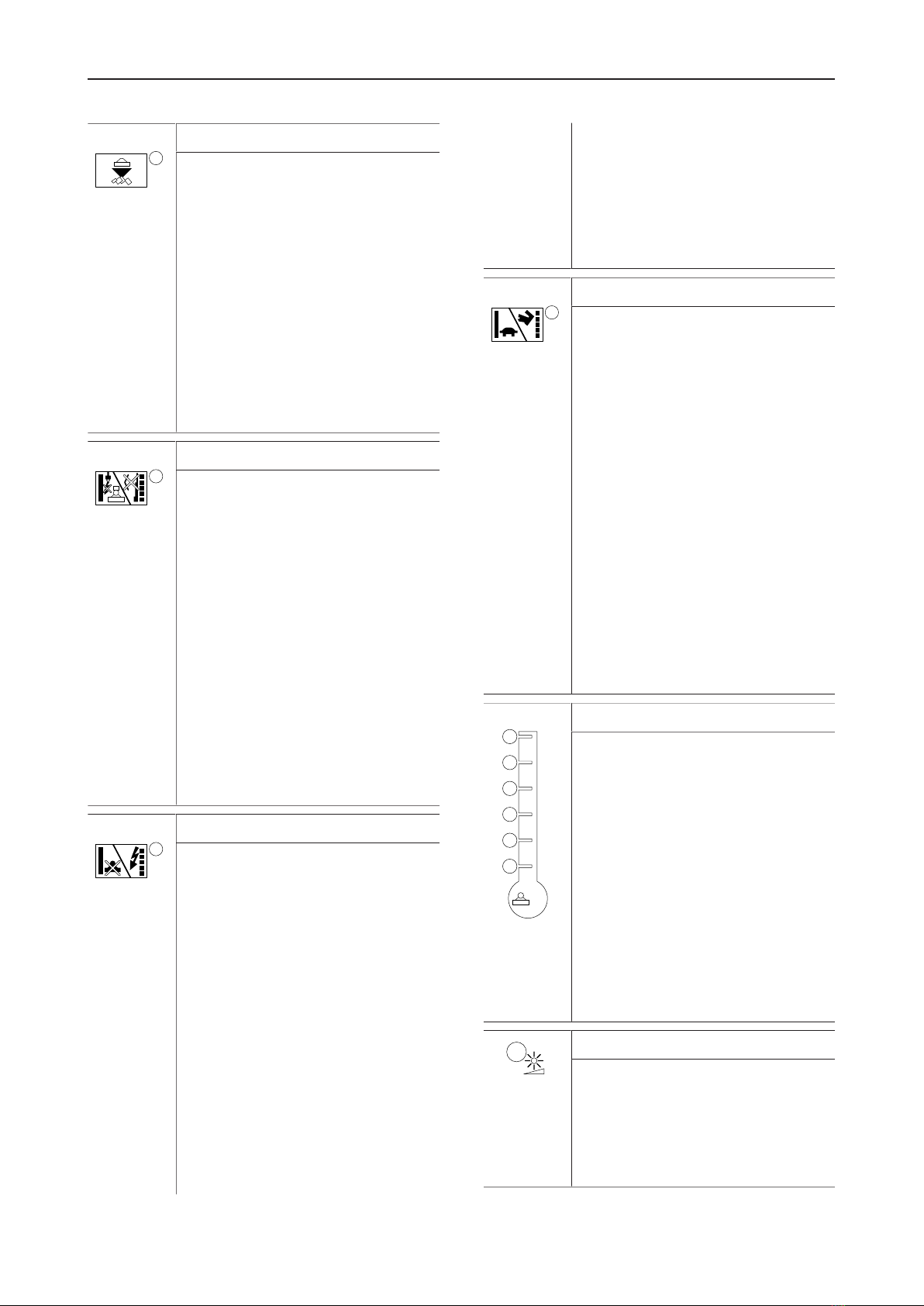
3.3.2 Labels
Warning for explosion
Warning for hot surface
Warning for hazardous electri-
cal voltage
Warning for non-ionizing elec-
tromagnetic radiation
Warning of suspended load
Warning of magnetic field

Safety and operating instructions
© Construction Tools GmbH | 3390 5149 01 | 2020-09-22
Original Instructions
19
Warning to persons with car-
diac pacemakers
The warning symbol and the
book symbol indicate that the
Safety and Operating Instruc-
tions must be read prior to use
of the hydraulic attachment and
in particular the chapter on
Safety.
3.4 Guarantee
The guarantee or product liability will be invalidated by
the following:
• Use other than intended
• Maintenance work not being carried out or being
carried out incorrectly
• The use of incorrect consumables
• The use of non-approved parts
• Damage due to wear
• Damage due to improper storage
• Changes not carried out by or in consultation with
the manufacturer
3.5 Removing the packaging
nRemove all the packaging material.
nDispose of it in accordance with the applicable provi-
sions.
nCheck that the delivery is complete.
nCheck the delivery for visual damage.
nIf any defects are found, consult the Epiroc Customer
Center / dealer in your area.
3.6 Scope of delivery
The Hydro Magnet is delivered complete with:
• Hydro Magnet
• Safety and operating instructions
• Spare parts list
• EC Declaration of Conformity
Accessories as ordered:
• Hoses
Special accessories as ordered:
• e.g. adapter plate with Allen screws and pairs of lock
washers
• e.g. base plate to construct an adapter plate with
Allen screws and pairs of lock washers
• e.g. hydraulic fittings for the carrier
• e.g. Joystick activation kit

Safety and operating instructions
20 © Construction Tools GmbH | 3390 5149 01 | 2020-09-22
Original Instructions
4 Transport
WARNING Hoist tipping over / hydraulic attach-
ment falling
The hydraulic attachment is heavy. The hoist/lifting
equipment and/or hydraulic attachment tipping over or
falling may cause serious injury and material damage.
uOnly transport the hydraulic attachment with lifting
equipment with the right load-bearing capacity for the
weight of the hydraulic attachment.
uOnly lift and secure the hydraulic attachment with lift-
ing gear (ropes, chains, shackles etc.) with the right
load-bearing capacity for the weight to be lifted.
uMake sure that there is nobody near or under the
suspended hydraulic attachment.
nFor transporting use four adjustable eyebolts with
washer and nut (3363106708) as lifting lugs. Stan-
dard eyebolts (DIN 580) are not permissible.
4.1 Transport using a crane
nInsert the four adjustable eyebolts from above into
the four holes (see figure) in the top plate.
nSlide one washer on each screw thread and screw
the nuts on.
nTighten the nuts.
nAttach ropes or chains to the adjustable eyebolts as
shown in the following illustration.
%
50
60
70
80
90
100
nSlowly lift the Hydro Magnet.
nPlace the Hydro Magnet on level ground.
nTurn the nuts from the adjustable eyebolts.
nRemove the washers from the screw threads and the
adjustable eyebolts from the top plate.
nStore the adjustable eyebolts, washers and nuts in a
safe place.
This manual suits for next models
4
Table of contents
Other Epiroc Construction Equipment manuals

Epiroc
Epiroc Secoroc COP 44 Specifications

Epiroc
Epiroc DEQ130141 Maintenance and service guide

Epiroc
Epiroc Flexi ROC T20 R Instructions for use

Epiroc
Epiroc DEQ171257 User manual

Epiroc
Epiroc SmartROC T35 User manual

Epiroc
Epiroc EC 90T User manual

Epiroc
Epiroc HC Series Maintenance and service guide

Epiroc
Epiroc FlexiROC T20 R Specifications

Epiroc
Epiroc Secoroc COP 54 User manual

Epiroc
Epiroc SB 52 User manual


