Bartell Global Innovatech PREDATOR P32N User manual

Predator 32N
Owner’s Manual
OIPB-I02001 Predator32N_V1.0 1 | P a g e 01/ 0 7 / 19
INNOVATECH PRODUCTS 4701 Allmond Ave, Louisville, Kentucky, USA 40209
Telephone: 1-425-405-9100 Toll Free: 1-800-267-6682 Fax: 1-425-405-9108
PREDATOR GRINDER POLISHER
P32N
OWNER’S MANUAL
www.BARTELLGLOBAL.com

Predator 32N
Owner’s Manual
OIPB-I02001-PREDATOR32N_V1.0 2 | P a g e 01/ 0 7 / 1 9
ORIGINAL LANGUAGE OPERATING MANUAL FOR
P32N GRINDER POLISHER
© 2015 Innovatech Products
No part of this work may be reproduced or transmitted in any form or by any means, electronic
or mechanical, including photocopying and recording, or by any information storage or retrieval
system without the prior written permission of Innovatech unless such copying is permitted by
federal copyright laws.
Address inquiries or reference permissions care of:
INNOVATECH PRODUCTS 4701 Allmond Ave, Louisville, Kentucky, USA 40209
REV.
DATE
DESCRIPTION
APPROVED BY:
-
01/7/19
Manual created
EC

Predator 32N
Owner’s Manual
OIPB-I02001-PREDATOR32N_V1.0 3 | P a g e 01/ 0 7 / 1 9
SAFETY PRECAUTIONS
DANGER
EXPLOSION HAZARD
Never operate the machine in an explosive
atmosphere, near combustible materials, or
where ventilation does not clear exhaust fumes.
WARNING
BURN HAZARD
Never come into contact with the engine or
muffler when engine is operating or shortly after it
is turned off. Serious burns may occur.
CAUTION
MOVING PARTS
Before starting the machine, ensure that all
guards and safety devices are in place and
functioning properly.
ATTENTION
READ OWNER’S MANUAL
Read and understand owner’s manual before
using this machine. Failure to follow operating
instructions could result in serious injury or death.

Predator 32N
Owner’s Manual
OIPB-I02001-PREDATOR32N_V1.0 4 | P a g e 01/ 0 7 / 1 9
TABLE OF CONTENTS
1.INTRODUCTION 5
2.SPECIFICATIONS 5
3.WARRANTY INFORMATION 6
4.SAFETY PRECAUTIONS 7
5.OPERATION INSTRUCTIONS 8
6.MAINTENANCE 9
7.TROUBLESHOOTING 9
8.FAULTS WHICH CANNOT BE AUTOMATICALLY RESET 10
9.PARTS DRAWINGS & DIAGRAMS 12
10.DECLARATION OF CONFORMITY 42

Predator 32N
Owner’s Manual
OIPB-I02001-PREDATOR32N_V1.0 5 | P a g e 01/ 0 7 / 1 9
1.INTRODUCTION
Innovatech Products and Equipment Company specializes in the manufacturing and distribution
of surface preparation equipment and supplies. From our early origins as a flooring removal
company, and a foundation based upon the success of our Terminator line of flooring removal
machines, Innovatech has transformed itself into an industry leader over a twelve-year period.
Our continued growth can be attributed to our pledge to offer only premium products, our
commitment to stand behind what we sell, and a staff well known throughout the industry for
their knowledge and commitment to our valued customers. Based on customer need,
Innovatech has proudly diversified our offerings to include a complete line of surface
preparation products including Shot Blasters, Scarifiers, Floor Grinders, Dust Collectors,
Diamond Abrasives, and other products.
2.SPECIFICATIONS
P32N
Cutting Width
32” (812mm)
Dimensions (Operating
Conditions)
57” x 33” x 52”
Weight
950lbs (431kg)
Tank Capacity
7 Gal (27L)
Cutter Heads/Tool Plates
Diameter
10.5” (270mm)
RPM
0 –1010rpm
Motor
15hp (11kW)
0-1765RPM
Power Source
Phase
3 Phase
Voltage
414 –504V
Hz
60Hz
Amps
25A

Predator 32N
Owner’s Manual
OIPB-I02001-PREDATOR32N_V1.0 6 | P a g e 01/ 0 7 / 1 9
3.WARRANTY INFORMATION
Innovatech warrants to original retail purchaser of the equipment:
A. LIMITED WARRANTY
The equipment, when first delivered, will conform to the specifications set forth in the
Owner’s Manual and will be without defect in material or workmanship. For a period of
one (1) year after delivery to the original retail purchaser, or 300 clock hours of
operation, whichever occurs first; or in the case of replacement parts other than belts, for
a period of ninety (90) days after the part is installed or within the warranty period
described above, whichever is later, if the original retail purchaser notifies Innovatech
(either directly or through one of Innovatech’s authorized dealers) of a defect in material
or workmanship or of a non-conformity to the specifications, then, upon confirmation of
the defect of non-conformity and confirmation that the defect or nonconformity is covered
within these Limited Warranty conditions, Innovatech will, at it’s election and at it’s
expense, either (i) repair or correct the defect and/or non-conformity, or (ii) replace the
part.
B. LIMITATIONS
This Limited Warranty does not apply to damage caused by (i) misuse of the equipment
including, with limitation, use of the wrong power source, striking an imbedded object
such as a bolt, electrical outlet box, expansion joint or steel reinforcing rod; or (ii)
unauthorized alteration, modification, repair or tampering; or (iii) use of replacement
parts not supplied by Innovatech; or (iv) normal wear, discoloration, surface corrosion,
deterioration of finishes or paint surfaces, or (v) other appearance deterioration caused
primarily by use. Innovatech shall not be responsible and this Limited Warranty shall not
apply to damage caused by improper maintenance or failure to inspect and maintain the
equipment as recommended in the Owner’s Manual.
C. BELTS
The Drive Belt is covered as set out at paragraph A., above, but for the period of six (6)
months after delivery or 250 clock hours of operation, whichever occurs first.
D. TRANSPORTATION
Purchaser will pay the cost of transporting defective or non-conforming parts to
Innovatech and the cost of returning repaired or replacement parts to purchaser. Each
party will safely package the parts it sends to the other in accordance with good
commercial practice. If purchaser requests and Innovatech agrees, Innovatech may
perform covered warranty work where the equipment is located. If Innovatech performs
the work at the location, purchaser will pay the cost of business class transportation and
good quality meals and lodging for Innovatech’s technicians.
E. ABUSE
Innovatech is not responsible for damage, defect, breakage, or malfunction of the
equipment that is caused by abuse or by operation of the equipment in a manner which
is not recommended or approved by Innovatech.
F. EXCLUSIVE WARRANTY
Except as is expressly set out in this limited warranty: (i) Innovatech makes no promise
or warranty, expressed or implied, with respect to the equipment; (ii) Innovatech makes
no promise or warranty that the equipment is fit for any particular purpose; (iii)

Predator 32N
Owner’s Manual
OIPB-I02001-PREDATOR32N_V1.0 7 | P a g e 01/ 0 7 / 1 9
Innovatech will have no obligation or liability to the purchaser or to any third party with for
any damage caused by the equipment or as a result or consequence of any claimed
defect in the equipment, any failure to warn or notify, or any claimed non-conformity to
the specifications; and (iv) Purchaser will have no other remedies in respect of such
defect, non-conformity, damage or condition except those set out in this limited warranty.
4.SAFETY PRECAUTIONS
1. Only persons who have received training are permitted to operate or repair the grinder.
2. Use personal safety equipment such as steel toe shoes, safety glasses, and earplugs.
3. Do not use grinder in area where there is a risk of explosion or fire.
4. Do not start the machine with heads off the ground.
5. Make sure the splashguard is on before stating machine.
6. Before you start grinding, check the floor for bolts, large holes and uneven joints. Hitting
these things can damage machine, tools, and cause personal injury.
7. Make sure all power supply is connected with the right voltage.
8. Use only cold water in water tank. Do not use chemicals in water tank.
9. When filling water tank, to avoid electrical hazards and injury, do not spill water onto the
machine motor and electrical box.
10.Switch off the machine power before changing grinding tools.
11.Disconnect power supply before working or repairing machine.
12.Be very careful with rolling machine on any sloping floors or ramps. The machine can roll
very quickly. Two people may be needed to handle and control the machine.
13.Use caution with removing the grinding tools after finished grinding. Tools can be very
hot. Use gloves to remove the plates.
14.When grinding glues, epoxy paints, or coatings, leaving the machine down on floor could
cause the head to stick to the floor. Always tip back machine as soon as the head comes
to a complete stop.
15.Always store machine in a dry place.
16.Only use Innovatech recommended tooling.
17.The operator must never leave the machine unattended during operation.
18.When grinding dry, use a suitable vacuum to extract the dust.
19.Innovatech is not responsible for any off gassing of hazardous gas that is generated by
grinding materials. It is the responsibility of the operator. Grinding floors containing
asbestos is especially dangerous and can cause health problems. Contact your state or
country for the proper way to handle it.

Predator 32N
Owner’s Manual
OIPB-I02001-PREDATOR32N_V1.0 8 | P a g e 01/ 0 7 / 1 9
5.OPERATION INSTRUCTIONS
Before starting:
1. Check the floor carefully and remove all bolts, nails, as well as any loose material that
could get caught in the machine.
2. Fit the appropriate tools to the machine.
3. Fit splash guard to the right height.
4. Connect the power supply. Make sure you have all the phases. May have to check with
volt meter.
5. If you are grinding dry, connect the appropriate vacuum and start vacuum before starting
the grinder.
Starting machine:
1. Turn main power switch on side of power box to ON.
2. Turn forward or reverse switch left of right.
3. Turn manual speed pot up to get the heads turning for desired speed. (If heads do not
move, you may have to lean on handle to reduce pressure on tools.
4. Always grip handle firmly when starting machine. The machine will always move from
side to side with first start.
5. When finished with grinding, turn off machine and let the heads come to a complete stop
before tilting back the machine.
Changing of Tools:
1. Before working on the grinder, bring the motor to a total stop and disconnect power.
2. Tilt machine back on floor.
3. Use caution! Tools can be very hot from grinding. Use gloves.
4. Use special tool supplied to turn center of tool holder to remove tool plate.
5. Replace with new tool plate and turn to lock in place.
6. Lower machine back down and re-adjust splash guard is necessary.
NOTE: IF THE WRONG POWER IS SUPPLIED TO THE GRINDER, IT WILL DAMAGE
THE ELECTRICAL COMPONENTS IN THE INVERTERS.

Predator 32N
Owner’s Manual
OIPB-I02001-PREDATOR32N_V1.0 9 | P a g e 01/ 0 7 / 1 9
6.MAINTENANCE
Clean machine after every use. To clean machine, use a low-pressure water hose or air
pressure. Do not use a high PSI pressure washer. This could force water into areas of the
machine unintentionally and damage parts. A regular inspection of machine for wear and
damage should be done on a regular basis. If any parts have been damaged or have excessive
wear, they should be replaced. If belt is needing replaced, please see separate instructions.
7.TROUBLESHOOTING
1. Check to see if main power supply is on.
2. Check to see if emergency stop is pushed down; if it is, pull up.
3. Check to see if manual speed pot is turned up past 1.
4. Check all cords ends for loose connection.
5. Check fuse in distribution box with test meter.
6. Check to see if all phase are with right voltage (check with voltmeter).
7. Check the converter connector cable to motor.
8. Check for error message on display of the converter.

Predator 32N
Owner’s Manual
OIPB-I02001-PREDATOR32N_V1.0 10 | P a g e 01/ 0 7 / 1 9
8.FAULTS WHICH CANNOT BE AUTOMATICALLY RESET
Faults which cannot be automatically reset are listed in the table below. To clear these faults:
1. Remove power from the drive controller.
2. Wait for the display to go off completely.
3. Determine the cause of the fault and correct it.
4. Re-apply power.
FAULT
PROBABLE CAUSE
REMEDY
B L F
Brake Sequence
•Brake release current not
reached
•Check the drive controller and motor
connections
•Check the motor windings
C r F
Precharge Circuit
Fault
•Precharge circuit damaged
•Reset the drive controller
•Replace the drive controller
I n F
Internal Fault
•Internal fault
•Internal connection fault
•Remove sources of electromagnetic
interference
•Replace the drive controller
O C F
Over Current
•Incorrect parameter settings in
the Set- and drC- menus
•Acceleration too rapid
•Drive controller and/or motor
undersized for load
•Mechanical blockage
•Clear the mechanical blockage
S C F
Motor Short Circuit
•Short circuit or grounding at the
drive controller output
•Significant ground leakage
current at the drive controller
output if several motors are
connected in parallel
•Check the cable connecting the drive
controller to the motor and check the
motor insulation
•Reduce the switching frequency
S O F
Over Speed
•Instability
•Overhauling load
•Check the size of the motor, drive
controller, and load
F n F
Aut-Tuning Fault
•Motor or motor power not
suitable for the drive controller
•Motor not connected to the drive
controller
•Check the presence of the motor during
auto-tuning
•If a downstream contractor is being used,
close it during auto-tuning
E P F
External Fault
•User defined
•User defined
L F F
•Loss of the 4-20 mA reference
on input A13
•Check the connection on input A13
•Loss of 4-20 mA follower
O b F
Over voltage
during
deceleration
•Braking too rapidly
•Overhauling load
•Increase the deceleration time
O H F
Drive Overload
•Drive controller or ambient
temperature is too high
•Continuous motor current load is
too high
•Check the motor load, the drive controller
ventilation, and the environment. Wait for
the drive controller to cool before
restarting

Predator 32N
Owner’s Manual
OIPB-I02001-PREDATOR32N_V1.0 11 | P a g e 01/ 0 7 / 1 9
O L F
Motor Overload
•Thermal trip due to prolonged
motor overload
•Motor power rating too low for
the application
•Allow the motor to cool before restarting
O P F
Motor phase
failure
•Loss of phase at drive controller
output
•Downstream contractor open
•Motor not connected
•Instability in the motor current
•Drive controller oversized for
motor
•Check the connections from the drive
controller to the motor
•Test the drive controller on a low power
motor or without a motor: set OPL to nO
O S F
Over voltage
during steady
state operation or
during
acceleration
•Line voltage too high
•Line supply transients
•Check the line voltage. Compare with the
drive controller nameplate rating
•Reset the drive controller
P H F
Input phase failure
•Input phase loss, blown fuse
•Three-phase drive controller
used on a single-phase line
supply
•Input phase imbalance
•Transient phase fault
NOTE: This protection only
operates with the drive controller
running under load
•Check the connections and the fuses
•Verify that the input power is correct
•Supply three-phase power if needed
C F F
Configuration
Fault
•The parameter configurations
are not suited to the application
•Restore the factory settings or load the
backup configuration, if it is valid
U S F
Under Voltage
•Line supply too low
•Transient voltage dip
•Damaged precharge resistor
•Check the line voltage
•Replace the drive controller
Predator 32N
Owner’s Manual
OIPB-I02001-PREDATOR32N_V1.0 12 | P a g e 01/ 0 7 / 1 9
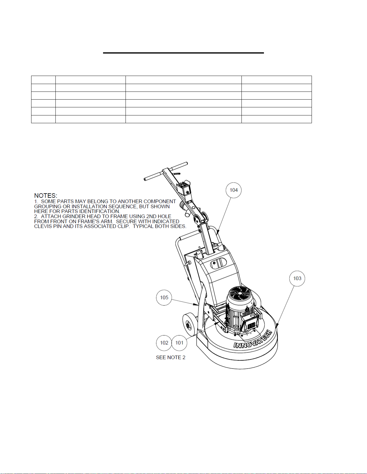
9.PARTS DRAWINGS & DIAGRAMS
P32N Grinder
ITEM
PART NO
DESCRIPTION
QTY
101
11-0082
Adjustable Clevis Pin, 5/8”*2-1/2”L
2
102
11-0052
Cotter Pin
2
103
96-0318
Grinder Head (P32N)
1
104
96-0325
Frame-Complete build-up (P32N)
1
105
825-0003
2”Hose
2

Predator 32N
Owner’s Manual
OIPB-I02001-PREDATOR32N_V1.0 13 | P a g e 01/ 0 7 / 1 9
Frame complete build-up(96-0325)
ITEM
PART NO
DESCRIPTION
QTY
201
13-0162
Linch Pin
2
202
54-0031
Wheel (10in)
2
203
11-0204
Flat washer
4
204
96-0317
Frame-32N, 32ND, 32NDX
1
Predator 32N
Owner’s Manual
OIPB-I02001-PREDATOR32N_V1.0 14 | P a g e 01/ 0 7 / 1 9
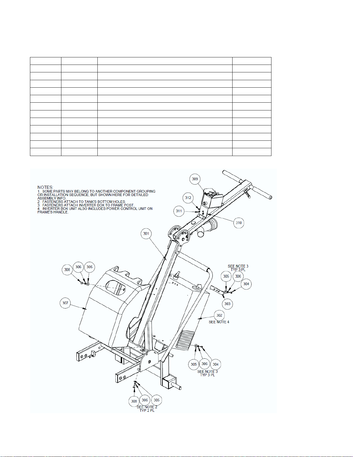
Frame complete build up- P32N, P32ND, P32NDX (96-0317)
ITEM
PART NO
DESCRIPTION
QTY
301
96-0293
Frame-Structure (skeleton) assy
1
302
96-0308
Inverter Box
1
303
51-0898
Inverter box attachment strip
1
304
11-0132
Hex head cap screw, 5/16”-18*1”
6
305
11-0034
Flat washer, 5/16”
10
306
11-0040
Split lock washer, 5/16”
10
307
54-0017
Water Tank
1
308
11-0018
Hex head cap screw, 5/16”-18*3/4”
4
309
23-0052
Power control box
1
310
52-0195
Bracket, Power control box
1
311
11-0069
Lock washer, ¼”
4
312
11-0349
Socket button head, ¼-20-5/8”
4
Predator 32N
Owner’s Manual
OIPB-I02001-PREDATOR32N_V1.0 15 | P a g e 01/ 0 7 / 1 9
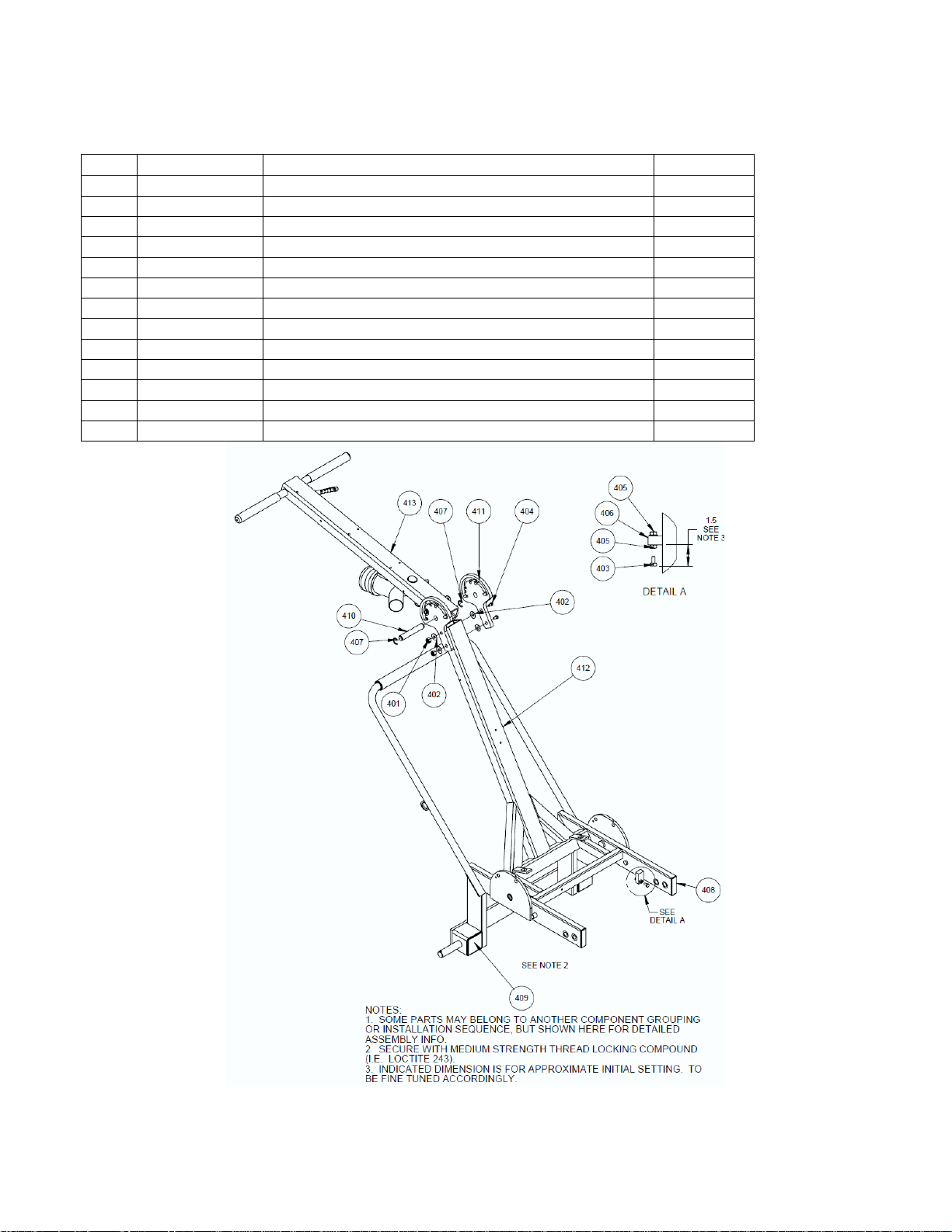
Frame- Structure (skeleton) assy (96-0293)
ITEM
PART NO
DESCRIPTION
QTY
401
11-0027
Steel Nylon-Insert Lock Nut, 7/16”-14 ZP
2
402
11-0036
Washer, 7/16”
4
403
11-0253
Hex head cap screw, 7/16”-14*3"
2
404
11-0219
Hex head cap screw, 7/16”-14*5”
2
405
11-0254
Nut, 7/16”-14
4
406
11-0320
Washer (split-lock), 7/16”
2
407
13-0144
Retaining Ring (E-Style)- for 3/4" shaft
2
408
13-0170
End cap, 1”*3”
2
409
13-0338
End cap, 2-3/4” square
2
410
51-0187
Handle hinge pin
1
411
53-0278
Handle tilt angle selection plate
2
412
53-0308
Frame-Base and post structure
1
413
96-0304
Frame- Handle Assy
1

Predator 32N
Owner’s Manual
OIPB-I02001-PREDATOR32N_V1.0 16 | P a g e 01/ 0 7 / 1 9
Frame Handle Assembly (96-0304)
ITEM
PART
DESCRIPTION
QTY
501
11-0007
Hex head cap screw, GR5, 3/8”-16*1”ZP
2
502
11-0139
Steel USS Flat Washer, 5/16”, ZP
3
503
11-0124
Steel hex nut, GR8: 3/8”-16, ZP
3
504
11-0129
Steel split lock washer, 3/8”, ZP
2
505
11-0234
Hex head cap screw, GR5:1/4”-20*2”L, ZP
1
506
11-0349
Button head socket cap screw, ¼”-20*5/8”
1
507
11-0351
Steel shoulder screw, 1/2”*3/8L, 3/8”-16 Thread
1
508
13-0147
Clevis Spring Pin
1
509
13-0150
Retaining ring (E-style, for 3/8" dia shaft)
2
510
13-0152
Steel Compression Spring: 4"Lx7/8"ODx0.08"WD
1
511
13-0155
3/8" ID Grip Cover
1
512
13-0212
Yoke end, 3/8"-16 threads, 3/8 pin holes
2
513
13-0285-05
Clamp (P-style, 5/8" dia.)
1
514
13-0347
Handle grip, 1" ID x 7-7/8" L
2
515
51-0170
Quick change lever
1
516
51-0173
Handle lock rod
1
517
51-0174
Spring Tension Block
1
518
51-0999
Rod (fully-threaded), 3/8"-16 x 2 ft long
1
519
53-0330
Y-coupler unit, pivotable
1
520
53-0331
Handle post (with handle bar)
1

Predator 32N
Owner’s Manual
OIPB-I02001-PREDATOR32N_V1.0 17 | P a g e 01/ 0 7 / 1 9
Grinder head- Complete unit (with shroud)- P32N (96-0318)
ITEM
PART NO
DESCRIPTION
QTY
601
11-0069
Split lock washer, ¼”
10
602
11-0234
Hex head cap screw, ¼”-20 x2”
10
603
11-0259
Flat washer, ¼”
10
604
54-0027
Splash Guard
1
605
54-0039
Shroud (cut-out panel)
1
606
96-0027
Cutter head-Floating Assy
4
607
96-0319
Shroud (main cover)
1
608
96-0321
Drum drive unit
1

Predator 32N
Owner’s Manual
OIPB-I02001-PREDATOR32N_V1.0 18 | P a g e 01/ 0 7 / 1 9
Cutter Head, Floating Head Assembly (96-0027)
ITEM
PART NO
DESCRIPTION
QTY
701
11-0036
Washer, 7/16”
2
702
11-0079
Hex head cap screw, 7/16”-14 x 1-1/4”
1
703
11-0147
Socket head cap screw, 3/8”-24 x 2”
4
704
11-0162
Washer (Belleville, serrated), 3/8” (0.413ID
X 0.630 OD)
4
705
11-0320
Washer (split-lock), 7/16”
1
706
11-0348
Flat head socket screw, 5/16-18 x ½”
3
707
13-0056
Flexible coupling
1
708
13-0186
Velcro mat
1
709
51-0139
Cutter head floating head bottom plate
1
710
51-0140
Cutter head floating head top plate
1
711
96-0025
Cutter head triangle holder assy
1

Predator 32N
Owner’s Manual
OIPB-I02001-PREDATOR32N_V1.0 19 | P a g e 01/ 0 7 / 1 9
Shroud (main cover, built-up) assy- P32N (96-0319)
ITEM
PART NO
DESCRIPTION
QTY
801
13-0156
P-clamp, ½”dia, black plastic
12
802
13-0161
Steel blind rivet w/ mandrel dom: 3/16 diax
0.251”-0.375”Thk
4
803
13-0172
Adhesive backed Velcro strip, 3”W X 112”L
1
804
13-0174
Rivet, 5/32dia, 1/4-3/8Thk
12
805
31-0078
Clear PVC tubing 3/8ID, 1/2OD, 1/16”Thk
4
806
32-0012
Adapter T-connector, 3/8 Nylon tube
4
807
51-0218
Grinder Shroud
2
808
54-0038
Shroud, main cover
1

Predator 32N
Owner’s Manual
OIPB-I02001-PREDATOR32N_V1.0 20 | P a g e 01/ 0 7 / 1 9
This page is left blank intentionally.
Table of contents


