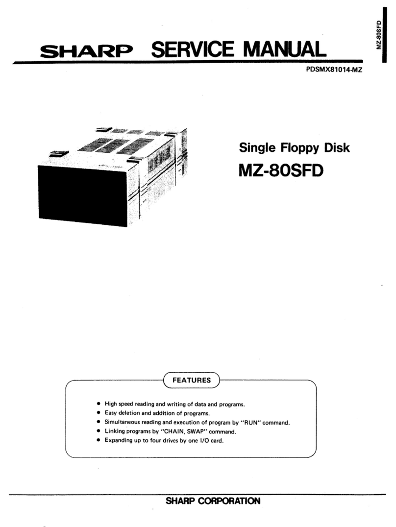
BASF 6106 User manual

SECTION 1
INTRODUCTION
i.i. GENERAL
This manual contains descriptive material and
procedures to aid personnel in the installa-
tion, operation, maintenance and repair of the
Model BASF 6106 Mini Disk Drive (Fig. 1-"• )•
1.2. RELATED DOCUMENTATION
Product and Interface
Specification 80 308-02E
1.3. DESCRIPTION
The BASF 6106 Mini Disk Drive is avery small
random access storage unit, yhich utilizes a
flexible mini disk cartridge as storage sediiaa.
The flexible disk is rotated at 300 RPM yiel-
ding adata transfer rate of 125,000 bits per
second. Up to 125 kBytes of data s&ay be sto-
red on asingle recording surface of the
mini disk when FM data recording is used Mien
utilizing the BASF data format of 16 sectors -each
with 128 bytes 81,92 kBytes of data may be re-
corded on the 40 tracks of the mini d:;?k. If
adata format of 9sectors each with 256 bytes is
used, 92,16 kBytes of data may be recorded.
The mini disk is driven by aDC- controlled
spindle drive motor, thus no AC -power :s
needed. The BASF 6106 uses the same tunnel
erase read /write head, as is used in the BASF
6102. The head is positioned with anew four-
phase DC- stepping motor actuator, utilising
aspiral wheel which gives precise location
of the read/ write head on the track.
Applications for the BASF 6106 mini disk drive
include woTd processing and text editing sys-
tems, program storage for mini and micro com-
puters, "intelligent" desktop calculators and
the micro hobby market.
FIGURE 1-1.MODEL BASF 6106 MINI DISK DRIVE
1-1

1.4. SPECIFICATION SUMMARY
Acomprehensive list of principal specifica-
tions are provided in Table 1-1.
PERFORMANCE SPECIFICATIONS
STORAGE CAPACITY
Unformatted
per Disk (40 Tracks)
per Track
Formatted
per Disk
Tracks per Disk
per Track
Sectors per Track
per Sector
TRANSFER RATE
ACCESS TIME
Latency
Maximum
Average
Track to Track
Average
Head Settling Time
Head Load Time
Drive Motor Start Time
FUNCTIONAL SPECIFICATIONS
Rotational Speed
Recording Density (inside Track)
Flux Density
Track Density
Track Radius
Track 00
Track 39
Encoding Method
Media Requirements
125,000 Bytes
3,125 Bytes
9SECTORS /TRACK 16 SECTORS /TRACK
92,160 Bytes 81,920 Bytes
40 40
2,304 Bytes 2,048 Bytes
916
256 Bytes 128 Bytes
125,000 bits/sec
200 msec
100 msec
12 msec
240 msec
max. 48 msec
max. 35 msec
max. 650 msec
300 RPM i2,5 '»
2768 BPI
5536 FCI
48 TPI
57,15 mm (2,25 in)
36,5125 mm (1 ,4375 in)
FM
BASF Flexidisk 5,25 or equivalent
TABLE 1-1•SPECIFICATION SUMMARY
1-2

1.5. OPTIONS SUMMARY
The following table lists the options of the
6106 mini disk drive.
1.5". 1.FACTORY INSTALLED OPTION
Option Function
Door Lock
Solenoid The door lock Solenoid
locks the front door under
control of the users soft-
ware .
TABLE 1-2.FACTORY INSTALLED OPTIONS
1.5.. JUMPER OPTIONS
The following options are selectable by jum-
pers on the PCB.
Option Function
RADIAL
SELECT Allows the connection of
three mini disk drives to
the host system. Each dri-
ve has its own address
(0,1,2) selectable by jum-
per .
AUTO SELECT The interface is always
enabled (Drive is always
selected)
.
The SELECT- Lines are not
used.
HEAD LOAD Loading of the head can
be accomplished in three
modes
:
•Selected Head Load
(INT. SELECT* HDLOAD)
•Auto Head Load
(INT. SELECT)
•Radial Head Load
(HEAD LOAD)
•The head will be loaded
only if the inserted mini
disk rotates.
Option
IN USE
DOOR LOCK
LATCH
DISK CHANGE
DOOR LOCK
ACTIVITY
INDICTOR
OPTIONS
WRITE
PROTECT
OPTION
STEPPER
MOTOR
SWITCHING
Function
Pin 34 of the interface
is used as IN USE input
signal and controls the
door lock solenoid and the
activity indicator.
If this Option is used the
disk change option must he
disabled.
Allows locking of the door
without maintaining the
IN USE signal activated by-
storing the state of the
IN USE -signal into the
IN USE -flipflop. To use
this option the IN USE -
option must by jumpered.
Notifies the host system
that the mini disk has
been changed. If this op-
tion is used, the IN USE-
option must be disabled.
Locking of the door can
be accomplished as
fol lows
:
1.by the IN USl--?icna:
2. by the IN USF-FF
(DOOR LOCK LATCH)
3. if the drive is se-
lected
(1/0 ENA activ)
4. if the head will he
loaded
(HDLOADENA activ)
5. if 1.or
if 1.
true
if 1.
if 1.
true
or _
or 4
or 2
is true
or 5.is
is true
or 4.is
The lighting of the acti-
vity LED is selectable by
jumper to one of the fol-
lowing conditions:
•the Head is loaded
and the drive is ready
•the door is locked
and the drive is ready
Allows protection of the
mini disk against over-
write if the write protect
notch is open (ECMA) or if
the write protect notch is
closed (SHUGART).
The stepper motor is
switched on and off to-
gether with the drive mo-
tor if ajumper is inser-
ted. If the jumper is not
inserted the stepper motor
will be enabled as long as
power is supplied.
TABLE 1-3.JUMPER SELECTABLE OPTIONS

PHYSICAL SPECIFICATIONS
Environmental Units
ambient temperature
(operation)
Relative humidity
Maximum wet bulb
DC- voltage requirements
Power Dissipation:
Mechanical Dimensions
Width
Height
Depth
Weight
RELIABILITY SPECIFICATIONS
MTBF:
Unit Life Time:
MTTR:
Error Rates: Soft Read Errors:
Hard Read Errors:
Seek Errors :
Media Life: Passes per Track
Insertions
10° to 50°C (50° Fto 120° F)
20 Ito 80 1
29°C (84°F)
*12 VDC !51
5VDC -51
max. 1,75 A•
max. 100 mV pp ripple
max. 0,7 A
max. 50 mV pp ripple
*plus motor starting current
max. 1,4 Afor max. 100 msec
10 watts operating
4,0 watts stand by (motor off)
7,5 watts motor- on and deselected
146,1 mm (5,75 in.)
53,5 mm (2,11 in.)
196,5 mm (7,74 in.)
1.4 kg
8000 POH under typical usage *
five years
30 minutes
1per 10^ bits read
1per lO^bits read
1per 10bseeks
5x10⁶
30 000
•Duty cycle of Spindle Drive Motor :25 2of POH
MEDIA SPECIFICATIONS
Jacket:
Disk :
Center Hole:
133,4 mm (5,25 in.) square
130,2 mm (5,125 in.) diameters
28,575 mm (1,125 in.)
TABLE 1-1(continued). SPECIFICATION SUMMARY

1.6. RECORDING MEDIA 1.7 RECORDING FORMAT
The BASF Mini Disk Drive uses aremovable
single sided flexible mini disk as
storage media. Fig. 1-2shows construction
and dimensions of atypical mini disk.
The recommended recording media for use with
the BASF 6106 is the BASF mini disk 606. The
mini disk is an oxide coated flexible disk en-
closed in aprotective plastic envelope. The
protective envelope contains aperture for head
contact, index detection, write protect de-
tection and spindle loading.
The write protect notch is used to protect the
written data on the mini disk (see 2. 2. 6.
Write Protect Detector).
The format of the data recorded on the mini
disk depends on the host system. The normal-
ly used encoding scheme for the BASF 6106
mini disk drive is frequency modulation re-
cording (FM). This scheme utilizes clocks to
define bit cell times. The presence of aflux
reversal between clock pulses is defined as a
"one'' bit. The absence of aflux reversal bet-
ween clocks is defined as a"zero" bit. On
the write data and read data interface lines
between mini disk drive and host system ev-
ery pulse represents aflux reversal on the
mini disk.
SEALED
PROTECTIVE
JACKET
OXIDE COATED
MYLAR DISK
LINER
TRACK 00 TRACK 39
B^s BTTCELL
WRITE DATA
DATA
-j*c""LJ"D~L_nT r
4A1S
mnn rn
iI
FIGURE 1-3.FM -ENCODING
Agroup of eight consecutive bit cells orbit
positions (B8 -B1) defines abyte. The most
significant bit is defined as B8, the least
significant bit is B1, as shown on fig. 1-4.
During awrite operation, the most signifi -
cant bit B8 is always transferred first.
Also, when the data is being read back from
the drive, bit 8of each byte will be trans-
ferred first.
iMSB ;lsb ;
i•
^8 D8F? C6D4C5C«C3D3C2D2P. D.
'.C8
-B8 -4- B74-B6 -+-B5-4- B4 «J-B3 4- B2 -J- BI-4" B6
•B8-+- B7-4-B6
1I
B4 *{•- B3*f-B2-*f-BI'
III
IBYTE
FIGURE 1-2.FLEXIBLE DISK CONSTRUCTION
AND DIMENSIONS FIGURE 1-4.BYTE
1-5

I.8. TRACK FORMAT TRACK GAP
The tracks of the mini disk may be formatted
in numerous ways, depending on the formatter
of the using system. The BASF 6106 can write
and read hard or soft sectored track formats.
The gap between the last data field and the
index puis is defined as Track Gap. It varies
slightly in length, due the write frequency
tolerances and the disk speed tolerances. It
is nominally 101 bytes in length.
1.8.1 SOFT SECTORED TRACK FORMATS
In asoft sectored track format the user may
record one long record or several smaller re-
cords on atrack. Two soft sectored track
formats with 16 and 9sectors per track are
described in the following chapters.
ADDRESS MARK (AM)- BYTE
.
The soft sectored track format needs unique
bit patterns to identify the beginning of ID
and Data Fields for synchronising the dese-
rializer circuit in the host system. The
unique bit pattern is called Address Mark (.AM).
AM- patterns do not contain clock bits in all
bit cells (all other data bytes must have clock
bits in every bit cell!).
There are three different AM- patterns used:
l.S.1.1. SOFT SECTORED TRACK FORMAT KITH
lo SECTORS/TRACK a' 128 BYTES
This format, which is recommended from BASF,
is shown fig. 1-6. It is similar to the IBM
-format.
The befinning of atrack is indicated by a
physical index pulse. Every record is prece-
ded by aunique record identifier. Record
identifiers and data fields are separated by
gaps. The gaps are necessary to allow the up-
dating of adata field without disturbing ad-
jacent fields.
INDEX GAP
This, gap starts with the index pulse and is
always 16 bytes in length. It is not affected
by any update write.
IDENTIFIER GAP
This gap consists of 11 bytes FFXand may
vary slightly in length after the data field
has been updated.
DATA GAP
This gap separates the data field from the
following ID- field and is 27 bytes in length.
It will vary slightly in length afterthe data
field has been updated.
•ID- AM
•DATA -AM
in front of aID-
Field
in front of aDa-
ta Field
DELETED DATA- AM in front of aDe-
leted Data Field
These AM are shown on Fig. 1
ID -AM:
SEP CLOCK (C7)
SEP DATA (FE)
DATA -AM:
SEP CLOCK (C7)
SEP DATA (FB)
f«n
F. c?hS
inn
IBYTE
III!
C4S<7
D8D7D6D5D4D3h
c8C7C6C5C4C3°2 Clf-8
nnn
Dg D7D6D5\D2D,
DELETED DATA -AM: I
c« c, %c5(^ c3tj c, ic 8
I""pI>
SEP CLOCK (C7)
SEP DATA (P8)
ii «
ii K
D8D7D6D5D4
FIGURE 1-5.ADDRESS MARK PATTERN

SECTOR IDENTIFIER
The sector identifier consists of the identi-
fier mark, the address identifier and the EDC
pattern.
IDENTIFIER MARK
This field comprise 7bytes (see Fig. 1-6).
The 6bytes of zeros in front of the address
mark byte are for synchronisation of the data
separator in the host system. The ID-AM- byte
.contains adata pattern of FE where the clock
bits C6, CS and C4 are missing as explained
before
.
2ND BYTE OF THE ADDRESS IDENTIFIER
This byte contains always 00.
SECTOR ADDRESS
Represents in binary notation the sector ad-
dress from 01 for the 1st sector to 16 for
the last sector of atrack.
4TH BYTE OF THE ADDRESS IDENTIFIER
This byte shall be always a(00-)- byte.
ADDRESS IDENTIFIER
The address identifier comprises the following
6bytes.
TRACK ADDRESS
This byte represents in binary notation the
track address from 00 for the outermost track
to 39 for the innermost track.
EDC -BYTES
These two bytes are hardware generated from
the host system by shifting serially the bits
of the sector identifier starting with the ID
-AM and ending with the 4th byte of the sec-
tor identifier through a16- bit shift regis-
ter described by the generator polomial
:
.16 x12 x51
(Fore more details read chapter EDC-
entation!
)
imple-
IKDEX GAPl SECTOR IDENTIFIER IDENTIFIER GAPfFIRST DATA BLOCK] DATA BLOCK CAP f||LAST DATA BLOCK! DATA BLOCK GAPlTRACK GAPi
ss
16 XFF 13 BYTES II XFF 137 BYTES 27 XFF 137 BYTES 27 XFF
11HI Mil -I—. I. »—!M-I! I. JO! X FF
r~T_
INDEX PULSE
SECTOR IDENTIFIER:
IDENTIFIER MARK ADDRESS IDENTIFIER EDC
6X00 FF. T) TRK 00 SEC 00 2BYTES
C7 2)
ID-AM
DATA BLOCK:
DATA MARK DATA FIELD EDC'
6X00 niy. 12SBYTES 2BYTXS
C7 2)
DATA-AM
1) DATA PATTERN
2) CLOCK PATTERN
•DELETED AM tFt
ID -AM.
SEP CLOCK (C7)
SEP DATA (PE)
DATA -AM:
SEP CLOCK (C7)
SEP DATA (PS)
Ps S'
IBYTE
SSC6SC
••••
4S*7 °\
IIII8
D5D4°3 4
>8 »> h
II I 1III
JCj cj Cj c5c4c3cj c, |r
nnp
Dg D, D§Dj D* D2D,
DELETED DATA -AH:
JB C7Cj C5C* Cj %C,
•» clock (CD iinnniiii
D8D7D6Ds D*
FIGURE 1-6.SOFT SECTORED TRACK FORMAT WITH 16 SECTORS/TRACK
1-7

DATA BLOCK
The data block contains the data Bark,
data field and the EDC- bytes.
the
the data block starting with the Data- AM and
ending with the last byte of the data field
through a16- bit shift register described by
the following generator polinomial:
16 12 _. 5
DATA MARK
This field comprises 7bytes (see Fig. 1-6).
The 6bytes of zeros in front of the data ad-
dress -ark are for synchronisation of the da-
ta separator circuit in the host system. The
data address mark byte contains FB in front
of anormal data field. When adeleted data
field follows, F8 must be written. The clock
pattern of the data address mark is C7 (C6,
CS and C4 missing).
DATA FIELD
This field comprises 128 bytes .If it comprises
less than 128 bytes, the remaining positions
shall be filled with zeroes.
EDC -BYTES
These two bytes are hardware generated by the
host system by shifting serially the bits of
EDC- IMPLEMENTATION
Fig. 1-7 is asimplified logic of ashift re-
gister, which may be used to generates the
EDC bytes.
Prior to the operation, all positions of the
shift register are set to ONE. Input data are
added (exclusive OR) to the contents of po-
sition C15 of the register to form afeed-
back .This feedback is in its turn added
(exclusive OR) to the contents of position C4
and position Cn .
On shifting, the outputs of the exclusive OR
gates are entered respectively into positions
Co, C5and Ci 2.After the last data pit has
been added, the register is shifted once more
as specified above.
The register then contains the EDC bytes. If
further shifting is to take place during the
writing of the EDC bytes, the control signal
inhibits exclusive OR operations.
To check for errors when reading, the data bits
are added into the shift register in exactly
the same manner as they were during writing.
After the data the EDC bytes are also entered
into the shift register as if they were data.
After the final shift, the register contents
will be all 2ER0 if the record does not con-
tain errors.
CONTROL
JcX^--^ JD^
L-IHPOT
OUTPUT
for EDC
writing
-FIGURE 1-7.SIMPLIFIED EDC SHIFT REGISTER

1.8.1.2. SOFT SECTORED TRACK FORMAT WITH
9SECTORS PER TRACK
In this format, which is shown on Fig. 1-8,
each sector contains 256 bytes.
INDEX GAPl SECTOR IDEKTIFIERI IDENTIFIER GAP|FIRST DATA BLOCK! DATA BLOCK GApPltLAST DATA BLOCK! DATA BLOCK GAPItRACK GAP
iioaa
265 BYTES k32+Y>.X FF R! 265 BYTES \(32+Y) XFF F32+ZTX~F?
XXFF 13BYTES II X FF
lit SECTOR
r~i_
INDEX PULSE
SECTOR IDENTIFIER:
XY+2-204 BYTES
IDENTIFIER MARK ADDRESS IDENTIFIER EDC
6X00 FF. 1) TRK 00 SEC 01 2BYTES
C7 2)
ID-AM
DATA BLOCK:
DATA MARK DATA FIELD EDC
6X00 FB !>• 256 BYTES 2BYTES
C7 2)
DATArAM
1) DATA PATTERN
2) CLOCK PATTERN
•DELETED AM :P8
+9t SECTOR
ID -AM.
SEP CLOCK (C7)
SEP DATA (PE)
DATA -AM:
SEP CLOCK (C7)
SEP DATA (FB)
£8C7<
ft mi
1BYTE
C, c6Cj C
'8 °7 D6D5D4
;'. \i
.
Cg C?C6C5C4C3C2 C, C
LA ±L II
D, D, D6 5 ^»2D,
ILI
DELETED DATA -AM:
jj C? %C
n
5SC3 *C]
D8D7D6°5 %
SEP DATA (P8) .mmMl M
FIGURE 1-8.SOFT SECTORED TRACK FORMAT WITH 9SECTORS/TRACK
1-9


SECTION 2
THEORY OF OPERATION
.i
.
FUNCTIONAL DESCRIPTION Functional Circuits:
The BASF 6106 comprises the following mecha-
nism functional circuits (see Fig. 2-1).
Mechanism:
•Drive Mechanism
•Spindle and Front Door Mechanism
•Positioning Mechanism
•Head Load Mechanism
•Interface
•Drive Motor Control
•HEAD LOAD-,. DOOR LOCK- and
ACTIVITY LED- Driver
•Track Zero Detector
•Write Protect Detector
•Index /Ready Detector
•Read /Write Circuits
•DC- Control and Power On Reset
Logic
SELECT l/
SELECT 2/
SELECT 3/
WRITE DATA/
WRITE GATE/
DIRECTION IN/,
IN USE/
(optional)
HEAD LOAD/.
MOTOR ON/
1/0 ENA WRJTE 1NK1EIT
Lt
READ /
WRITE
CIRCUITS
WRT CURRENT or RD PLAYBACK
ERASE
CURRENT
DRIVE
MOTOR
CONTROL
VRT-ERASE CURRENT
5V DC
«12V DC
DC- I
CONTROL I?
AND r
PR#T0N 1
DC-MDTOR
INDEX/
READY
1>ETECT0R
INDEX
—
r
SPEED
DC-
CONTROL |PWR ON RESFT
AND "*"
WRITE
PROTECT
DETECTOR
:
READ
DATA/
TRACK 00/
INDEX/
READY/
DISK
CHANGE
/
(optional)
WRITE
PROTECT/
FIGURE 2-1.BLOCK DIAGRAM BASF 6106

2.1.1. DRIVE MECHANISM
The spindle is rotated at 300 rpm by aDC drive
motor. Rotation of the spindle is provided by
abelt and pulley. The drive motor is star-
ted and stopped by the interface signal MOTOR ON.
SPINDLE DRIVE HUI
DRIVE MOTOR
SPINDLE DRIVE
PULLEY
FIGURE DRIVE MECHANISM
2.1.2. SPINDLE AND FRONT DOOR MECHANISM
The main parts of this mechanism are the drive
hub, the centering cone, the centering cone
expander and the front door with pressure arm
and door latch, (see Fig. 2-3)For loading
adisk the mini disk is inserted and the front
door pressed. The pressure arm moves down ,
the centering cone enters the mini disk. Just
before the centering cone reaches the fully
down position, the centering cone expander is
e=,—llfari
activated and expands the centering cone which
grips the inner diameter of the mini disk to
ensure correct alignment. The door latch is
activated and holds the front door in aclo-
sed position. For unloading adisk, the front
door must be pressed again. The door latch
opens and the pressure arm is moved upwards
by aspring. The centering cone and centering
cone expander also move upwards and disenganges
the mini disk from the drive hub.
CENTERING CONE EXPANDER
da]P1[n r
ICENTERING CONE
FRONT DOOR (opened)
FRONT DOOR (closed)
DRIVE HUB
DOOR LATCH
FIGURE 2-3.SPINDLE AND FRONT DOOR MECHANISM

2.1.3. POSITIONING MECHANISM
The main parts of the positioning mechanism
are (see Fig. 2-4)
.
•Stepper Motor
•Spiral Wheel
•Carriage Assembly
The stepper motor is afour phase motor and
is rotated 15° by every step pulse. The spiral
wheel directly connected to the shaft of the
stepper motor converts the rotational motion
of the stepper motor to alinear motion of
the read write head.
The carriage assembly consists of the read/
write head, the head load pressure arm and
two guide bars. The read/write head is inser-
ted in the carriage assembly, which rides on
the two guide bars. The mini disk is pressed
against the read/write -head load pressure
arm. The head load pressure, arm is released
by the head load mechanism.
GLIDE BARS
R/W -HEAD
HEAD LOAD PRESSURE ARM
STEPPER MOTOR
SHAFT
FIGURE 2-4.POSITIONING MECHANISM
2-3

2.1.4. HEAD LOAD MECHANISM
The head load mechanism comprises
(see Fig. 2-5)•
•Head Load Solenoid
•Head Load Actuator
When the head load solenoid is energized the
head load actuator releases the head load pres-
sure arm of the carriage assembly, which in
turn presses the mini disk against the read/
write head by the head load pad. The pressure
pad under the head load actuator stabilizes
the mini disk. When the head load solenoid is
de- energized, the head load actuator is lif-
ted by aspring. Also the head load pressure
arm is lifted.
HEAD LOAD PRESSURE ARM
EAD LOAD PAD
HEAD LOAD ACTUATOR
HEAD LOAD SOLENOID
FIGURE 2-5.HEAD LOAD MECHANISM

2.2. LOGIC DESCRIPTION
2.2.1. INTERFACE LOGIC
The interface logic consists of two parts
(see Fig. 2-6)
•the input interface
•the output interface
imii imimtui
A"I
mi
HUH. P4
•»
h—M£y
;&-
>
i.. ......
-
pi- —MMUMWmM.
4>-
-IU-J-:
&
IWI^ I*» /
IMM!
attic na
-mBiatniMM
rMl ,
I•m'
<;TH
tow
ciatun
rtf)^"-
:]>
'
—
1>—ti!"
•»« .NBTCM jgg^ rq.-: fc>=s
*=I>
r—™>
.-.334t5K4lM4jte«fc*M -<m,,»^i> «ii i»»i»i« <r riiiiiinir nut, unwitiM t>ir<naft"i:nr<wvuimmr-^i:i^
:]>*mD.U .
4V
FIGURE 2-6.INTERFACE LOGIC
2-5

2. 2. 1.1. INPUT INTERFACE 2.2. 1.2. OUTPUT INTERFACE
The input interface receives the signals from
the host system Table 2-1lists and defines
the input signals.
The input lines are terminated by pull up re-
sistors of 150 Ohm. In aradial configuration
only the last drive will contains the pull
up resistor network.
The receivers sends the input lines to the
different parts of the drive electronics.
SIGNAL NAME
SELECT
d-3) /
WRITE DATA/
WRITE GATE/
MOTOR ON/
DEFINITION
Selects the desired mini disk drive.
Enables when used all other interface
lines except MOTOR ON and
DIRECTION IN.
This line carries low active pulses
representing data to be recorded on
the mini disk
A
200 nsec min L
.AH
20 ns
8,00 >usec -40 nsec
Low input enables recording of WRITE
DATA on disk
High input enables reading from the
mini disk
DIRECTION IN/
STEP/
HEAD LOAD/
IN USE/
(OPTION)
This line turns on the drive motor
and the stepper motor and is not
gated by SELECT. Arecalibrate oper-
ation must be performed to obtain cor
rect head positioning every time af-
ter the MOTOR ON signal goes active.
Switching of the stepper motor may be
disabled by removing ajumper. This
avoids recalibrating after switching
on the drive motor.
Defines motion of the read write head
LOW -in (towards Track 39)
HIGH- out (towards Track 0)
This line is not gated by aelect
Used in conjunction with DIRECTION IN
and causes the read/write head to be
moved from track -to -track.
This line is used to press the mini
disk against the read/write head if
the mini disk drive is ready. To
activated this line ajumper has to
be changed.
This line controls the door lock
solenoid. Also the activity LED can
switched on. If the IN USE/ signal is
used, the disk change option must be
disabled.
The output interface sends the read data
pulses and the status signals WRITE PROTECT,
INDEX, READY, TRACK 00 and DISK CHANGE (op-
tional) to the host system (see Table 2-2).
The output signals are gated by I/O- ENABLE
and driven by the output drivers SN 7438.
SIGNAL NAME
READ DATA/
WRITE
PROTECT /
INDEX/
TRACK 00/
READY /
DEFINITION
This Line provides the "raw data
as detected by the read electronics.
500 nsec
-20 1
4**——•*!
8/usee 4ais
NOM NOM
Low active status indicates that a
write protected mini disk is installed
The BASF 6106 will inhibit writing
with awrite protected mini disk in-
stalled.
The leading edge of this signal indi-
cates the beginning of atrack when
soft sector format is used.
200 msec
DISK CHANGE/
(OPTION)
2msec 202
If a hard sectored disk is used this
signal indicates the sensing of a
index or sector hole. To indicate the
beginning of atrack one index pulse
is sensed in the middle of sector 15.
12.5 msec
t
6,2 5msec
Sc
SECTOR ISECTOR
14 '15
SECTOR (SECTOR
This Line indicates that the read /
write head is positioned at track 00.
This line indicates that the inserted
mini disk has reached more than 60 Z
of full operation speed and two con-
secutive INDEX- pulses has been sensed
For hard sectored mini disks Ready is
activated as soon as the mini disk
starts turning and two consecutive
SECTOR pulses has been sensed.
Aactive (low) signal is provided when
the SELECT- line is activated if the
drive while deselected has gone from a
Ready to aNot Ready condition.
TABLL 2-1.INPUT SIGNALS TABLE 22.OUTPUT SIGNALS

2. 2. 1.3. JUMPER OPTIONS
The following options can be selected by
jumpers:
•Select Options
•Head Load Options
•IN USE Options
•Door Lock Latch Option
•Door Lock Options
•Activity LED Option
•Write Protect Option
•Stepper Motor Switching
Select Options
There are two possibilities to select the
mini disk drive.
•Auto Select
•Radial Select
Auto Select
This option is used when no SELECT-lines are
used. The input and output interface are al-
ways enabled, because I/O- ENA is forced to
ahigh. To install the AUTO SELECT option
PIN 7and 8of JJ2 Bust be jumpered (see Fig.
2).
Radial Select
If Radial Select is used max. three mini disk
drives can be connected to the host system.
The signal SELECT 1/ will select the mini disk
drive jumpered between JJ1 1-2, SELECT 2/ will
select the mini disk drive jumpered between
JJ1 3-4 and SELECT 3/ will select the mini disk
drive jumpered between JJ1 5-6. Only one se-
lect jumper is allowed in one drive. For
enabling of the Radial Select Option JJ2 5-6
must be jumpered and the Auto Select Option
must be disabled by removing Jumper JJ2 7-8.
JJ2
SELECT 1/
SELECT 2/
SELECT 3/
DRIVE #
JJI
112I
an<
32A
-© —<
536^
'JJ2
II"J
INT. I'
SELECT 56|
II
ij
l/O-ENA
FIGURE 2-7.AUTO SELECT OPTION FIGURE 2-8.RADIAL SELECT OPTION
2-7

Head Load Options
There are three possibilities for the
to load the head. user
•Auto Head Load
•Selected Head Load
•Radial Head Load
Auto Head Load
This Option allows the user the read /write
head to be load as soon as the mini disk dri-
ve is selected. If auto head load is desired
the jumpers must be set as shown in Fig. 2-9 .
riii»
£—-o-j 1—
*
i—
t
!!ij
HEAD LOAD/
FIGURE -9AUTO HEAD LOAD OPTION
J.I.'
II
INT. SELECT/
JJ3
r
13 14
I"-
HEAD LOAD/
10
r&HEAD LOAD UNA/ 1.0 •.!
(IK-
SPF.ED LITS
FIGURE 2-10 .SELECTED HEAD LOAD OPTION
Radial Head Load Option
This option allows the user to keep the head
loaded without selection of the mini disk
drive. The 48 msec head load time is then
eliminated. To install this option see Fin
2-II .
JJ2
Selected Head Load Option
In this configuration the head is loaded when
the mini disk drive is selected and the
HEAD LOAD signal is activated (see Fig. 2-10). FIGURE 2-11 .RADIAL HEAD LOAD OPTION
2-8

Door Lock Latch Option (Fig. 2-12 )
This option can be used if the IN USE Option
is already installed. Then, the door lock
latch option will allow the latching of the
door lock solenoid under control of the
SELECT and IN USE signals without maintaining
the IN USE signal activated. The IN USE-FF
stores the state of the IN USE- signal when
the drive is selected (see Fig. 2-13 ). The
door lock solenoid remain activated even if
the mini disk drive is deselected and the
IN USE- signal is deactivated. To unlock the
door the mini disk drive must be selected a-
gain with IN USE inactive (low). To enable
the Door Lock Latch Option ajumper must be
installed on JJ2 between Pin 11 and 12.
IN USE Option
Pin 34 of the interface can be used for the
In Use option if JJ2 is jumpered from Pin 13
to 14. The IN USE- Signal is used to turn on
the door lock solenoid, also the IN USE sig-
nal can be used to turn on the activity LED.
If the IN USE option is used the DISK CHANGE
Option must be disabled by removing the
jumper on JJ2 between PIN 11 and 12.
jj:
'ii
IN USE/i
DISK I
CHANGE /I 131 14
Ame
12
o-f
{> TN USE-
FF
4,
I/O ENA «— DQ
CQL.
K
JJA
Jol
I
I
J2I
i__J
POWER ON RESET/
DOOR
LOCK
ENA
Write Protect Option
This option allows the user to decide by set-
ting of jumpers in which fashion the mini disk
is protected against overwriting. He can
selecting that the mini disk is protected
either if the Notch are open or if the notch
is covered as shown on the following table.
JUMPER NOTCH OPEN NOTCH COVERED REMARKS
JJ4:3-4
JJ3:5-6 unprotected protected Shuga it
JJ3:3-4 protected unprotected ECMA-Norm
FIGURE 2-12 .DOOR LOCK LATCH OPTION TABLE 2-3 .WRITE PROTECT JUMPERING
IN USE
INT. SELECT
IN USE FF
Front Door unipcKea 'Wked if Lni ocKeo
FIGURE 2-13 .TIMING DIAGRAM DOOR LOCK LATCH
OPTION
Stepper Motor Switching
The stepper motor can be switched on and off
by the MOTOR ON- signal, if there is ajumper
installed between JJ4 Pin 3and 4. If this
jumper is installed the mini disk drive must
be repositioned by arecalibrate operation
every time the drive and stepper motor are
turned on.
2-9

Door Lock Options
There are several possibilities to lock the
front door:
1. Locking by the IN USE signal
2. Locking by the Door Lock Latch
Option
3. Locking while the drive is selected
4. Locking while the head is loaded
Also the circuit allow combinations of the
possibilities written above:
Locking while the drive is selected
The front door is locked as long as the drive
is selected. The jumpers must be set as fol-
lows :
Install JJ2 JJ3
5-6 7-8
y-io
Remove jj:
1-2
5. If 1. or 3.
6. If 1. or 2.
"
.
If I.or 4
.
S
.
If I.or 2
.
is true
or 3. is true
is true
or 4. is true
Locking while the head is loaded
The front door is locked as long as the read/
write head is loaded. To alio** this option
the following jumpers must be installed.
Install :JJ3
11-12
9-10
Remove
:
JJ3
I-2
Locking by the IN USE signal
The front door is locked as long as the
IN USE- signal is activated. For this option
the following jumpers must be installed.
JJ2 JJ5 JJ4
13-14 1-2
9-10
9-10
Combinations of the previous described pos-
sibilities
If combinations of the above described door
lock options are wished to use for locking
the front door, the jumper JJ3 9-10 must be
removed. The following combinations are pos-
sible.
DOOR LOCK -DOOR LOCK ENA HEAD LOAD ENA
DOOR LOCK -DOOR LOCK ENA +I/ENA
DOOR LOCK -DOOR LOCK ENA «IN USE +IN USE FF
Locking by the Door Latch Option
The front door stays locked as long as the
IN USE- FF is set. The following jumpers
must be installed:
To install this combinations all jumpers of
the wished combination must be installed ex-
cept JJ3 9-10. (see also Installation and
Operation)
JJ2 JJ3 JJ4
13- 14 1-2
9-10
11-12
Activity Indicator Options
The activity indicator is switched on when
the drive is up to speed (SPEED-FF is set)
and the read/write head is loaded (Jumper JJ4:
7-8) or the door is locked (Jumper JJ4: 5-6).
Other manuals for 6106
2
Table of contents
Other BASF Floppy Disk Drive manuals
