BASF 6106 User manual

6106
SINGLE-HEADED
6108 DOU.BLE-HEADED

REVISION
RECORD
OF
REVISION
REMARKS
,
*
01
VS
Il
Valid
for
SN
0000
-/-
0400
,
,
02
VS
111
Valid for
SN
0500
-/-
1300
l
03
VS
IV
Valid for
SN
2100
-/-
~
04
Corrections
05
Add.
Model
6108
Va
1id for
Dri
ves
with
PCS":\T
88366
11

L
IST
0 F C 0 N T E N T S
SECTION
PAGE
SECTION
PAGE
1.
INTRODUCTION
1-1
1.1
Genera
1 1-1
2.2.8
Type
of
Heads
2-20
1.2 Related oocumentation 1-1
2.2.8.1
Read/Write
Head
2-20
l.J
Description 1-1
2.2.8.2
Side Select
Logic
2-21
1.4 Specification
Summary
1-2
2.2.9
Write
Ci
rcuits
2-22
1.5
Options
Summary
1-4
2.2.9.1
Wr
ite
In
it
i
ate
2-22
1. 5.1 Factory
Installed
Option 1-4
2.2.9.2
Write Logic 2-22
1.
5.
2
Jumper
Options 1-4
2.2.9.3
Erase
Delay
Logic
2-24
1.6 Recording
Media
1-5 2.2.10
Read
Circuits
2-25
1.7 Recording Formats 1-5 2.2.10.1
Read
Initiate
and
Read
Block
2-25
1.7.1
FM
Encoding
1-5
Diagram
1. 7.2
MFM
Encoding
1-5 2.2.10.2 Read/Write Select 2-26
1.8
Track
Format
1-6 2.2.10.3
Read
Amplifiers
and
Filter
2-26
Network
1.8.1 Soft Sectored
Track
Formats 1-6 2.2.10.4 Active
oifferentiator
and
2-27
1.8.1.1
Soft Sectored
Track
Format
1-6 Comparator
for Single Density with 2.2.10.5
Time
oomain
Filter
and
Crossover 2-27
16
Sec
tors/Track ä
128
Bytes
oetector
1.8.1.2
Soft Sectored
Track
Format
1-9 2.2.10.6
Timing
Diagram
Read
Circuits
2-28
for Single oensity
(9
Sec
tors
per
Track
ä
256
Bytes) 2.2.11 oC-Control
and
Power
On
2-29
1.8.1.3
Soft Sectored
Track
Format
1-10 Reset Logic
for
Double
oensity 2.2.11.1
DC-Control
2-29
(16
Sectors per
Track
a
256
Bytes) 2.2.11.2
Power
On
Reset
Logic
2-29
2.
THEORY
OF
OPERATION
2-1
2.1 Functional oescription
2-1
2.1.1 Drive
Mechanism
2-2
2.1.2
Spindle
and
Front ooor
Mechanism
2-2
2.1.3
Positioning
Mechanism
2-3
2.1.4
Head
Load
Mechanism
2-4
2.2
Logic
Description 2-5
2.2.1
Interface
Logic
2-5
2.2.1.1
Input
Interface
2-6
2.2.1.2
Output
Interface
2-6
2.2.1.3
Jumper
Options 2-7
2.2.2
Stepper
Motor
Control 2-12
2.2.3
Drive
Motor
Control
2-14
2.2.4
Head
Load
Logic
2-15
2.2.5
Track
Zero
oetector
2-16
2.2.6
Write Protect
oetector
2-17
2.2.7 Index/Sec
tor-
and
Ready
Detector 2-18
2.2.7.1
Index/Sector oetection 2-18
2.2.7.2
Ready
Oetection 2-19
III

l
IST
0 F C 0 NT E NT S
SECTION
3.
3.1
INSTALLATION
AND
OPERATION
Installat
ion
3.1.1 General
3.1.2
Unpacking
and
Inspection
3.1.3
Connecting Cables
3.1.4
Connectors
3.1.4.1
DC-Connector
3.1.4.2
Signal Connector
3.1.4.3
Frame
Connector
3.1.4.4
Interconnecting
Diagram
3.1.5
Logic
Levels
and
Termination
3.1.6 Connecting Configuration
3.1.6.1
Single Drive Configuration
3.1.6.2
Multiple Drive Configuration
3.1.7
Selection of the Desired Option
3.1.7.1
Selection Options
3.1.7.2
Head
Load
Options
3.1.7.3
In
Use
/
Disk
Change
Option
3.1.7.4
Door
Lock
Options
3.1.7.5
Activity
LED
Options
3.1.7.6
Write Protect Option
3.1.7.7
Stepper
Motor
Switching
3.1.7.8
Jumper
Matrix
3.1.8
Drive
Mounting
3.1.8.1
Mounting
Positions
3.1.8.2
Mounting
Dimensions
3.2 Operation
3.2.1 General
3.2.2
Mini
Disk
Storage
and
Handling
3.2.3 Write Protect
3.2.3.1
Write Protect
if
notch
open
(optional)
3.2.3.2
Write Protect
if
notch covered
(ECMAl
4.
4.1
4.2
4.3
4.3.1
4.3.2
MAINTENANCE
General
Too1s
and
Test
Equipment
Checks, Adjustment
and
Replacements
PCS
Replacement
Spindle Drive
System
PAGE
3-1
3-1
3-1
3-1
3-2
3-2
3-2
3-2
3-2
3-2
3-4
3-4
3-4
3-4
3-6
3-6
3-6
3-6
3-6
3-7
3-7
3-7
3-8
3-10
3-10
3-10
3-11
3-11
3-11
3-12
3-12
3-12
4-1
4-1
4-1
4-2
4-2
4-2
IV
SECTION
4.3.2.1
Drive
Motor
and
Drive
8elt
Checks
4.3.2.2
Drive Belt Tension
Check
4.3.2.3
Drive Belt Replacement
and
Tension Adjustment
4.3.2.4
Drive
Motor
Speed
Check
4.3.2.5
Drive
Motor
Speed
Adjustment
4.3.2.6
Drive
Motor
Speed
Adjustment
using a Frequency Counter
4.3.2.7
Drive
Motor
Replacement
4.3.3
Positioning
System
4.3.3.1
Track Adjustment
Check
4.3.3.2
Track
Adjustment Procedure
4.3.3.3
Adjustment
Check
for
Optical
Track
Zero
Switch
4.3.3.5
Track
Zero
Switch Replacernent
4.3.3.6
Head
Carriage Replacement
4.3.3.7
Head
Load
Pad
Replacement (6106)
4.3.4
Head
Load
Mechanism
4.3.4.1
Head
Load
~olenoid
Replacement
4.3.4.2
Head
load Actuator
Check
4.3.5
Read/Write Electronics
4.3.5.1
Jitter
Check
and
Adjustment
4.3.5.2
Read
Amplitude
Check
4.3.6
Photo Transistors
and
LED's
4.3.6.1
Photo
Transistor
Replacement
4.3.6.2
lED-Replacement
4.3.6.3
Index
Detector Adjustrnent
Check
4.3.6.4
Index Detector Adjustment
4.4 Location of Testpoints,
IC's,
Potentiornenters
and
Connectors
Spare Parts
PAGE
4-2
4-2
4-3
4-3
4-3
4-4
4-4
4-5
4-5
4-6
4-7
4-8
4-9
4-9
4-10
4-10
4-10
4-11
4-11
4-11
4-12
4-12
4-12
4-12
4-13
4-14
5.
5.1 Attachment
I,
Spare
Parts
for
BASF
6106
5.2
Attachment
2,
Spare Parts for
BASF
6108

FIGURE
1 - 1
1 - 2
1 - 3
1 - 4
1 - 5
1 - 6
1 - 7
1 - 8
1 - 9
2 - 1
2 - 2
2 - 3
2 - 4 a
2 - 4 b
2 - 5 a
2 - 5 b
2 - 6
2 - 7
2 - 8
2 - 9
2 -
10
2 -
11
2 -
12
2 - 13
2 -
14
2 -
15
2 -
16
2 -
17
2 -
18
2 -
19
2 -
20
2 -
21
2 -
22
2 -
23
2 -
24
2 -
25
2 -
26
2 -
27
2 -
28
2 -
29
L
IST
0 F I L L U S T
RAT
ION
S
Model
BASF
6106/6108
Mini-Disk-Drive
Flexible
Disk
Construction
and
Dimensions
FM-Enco
din9
MFM-Enroding
Address
Mark
Patterns
Soft Sectored
Track
Format
with
16
Sectors per
Track
Simplified
EDC
Shift
Register
Soft sectored
Track
Format
with 9 Sectors per
Track
Soft Sectored
Track
Format
fOI'
Double
Density
(MFM)
PAGE
1-1
1-5
1-5
1-5
1-6
1-7
1-8
1-9
1-10
Block
Diagram
BAsF
6106/6108 2-1
Drive
Mechanism
2-2
Spindle
and
Front
Door
Mechanism
2-2
Positioning
Mechanism
6106
Positioning
Mechanism
6108
Head
Load
Mechanism
6106
Head
Load
Mechanism
6108
Interface
Logic
Auto
select
Option
Radial Select Option
Auto
Head
Load
Option
Selected
Head
Load
Option
Radial
Head
Load
Option
Door
Lock
Latch Option
Timing
Diagram
Door
Lock
Latch Option
Disk
Change
Logic
Timing
Diagram
Disk
Change
Logic
Stepper
Motor
Control
Stepper
Motor
Timing
Diagram
Drive
Motor
Control
Head
Load
Circuit
Door
Lock
Solenoid
and
Activity
LED
Driver
Head
Load
Timing
Diagram
Track
Zero
Detector
Track
Zero
Timing
Diagram
Write
Protect
Detector
Index
Detector
Ready
Detector
Ready
Timing
Track
Geometry
Electrical
Connection of the
Read/Write
Head
Side Select Logic
2-3
2-3
2-4
2-4
2-5
2-7
2-7
2-8
2-8
2-8
2-9
2-9
2-11
2-11
2-13
2-13
2-14
2-15
2-15
2-16
2-16
2-17
2-18
2-19
2-19
2-20
2-20
2-21
v
FlGURE
2 -
30
Write
Initiate
Timing
2 -
31
a Simplified Write Circuits
6106/6108
2 -
31
b
Timing
Diagram
Write Operation
(Simplified)
2 - 32
2 -
33
2 -
34
2 -
35
2 -
36
2 -
37
2 -
38
Erase
Delay
logic
Erase
Delay
Timing
Read
Circuits 6106/6108
(Simpl
ified)
Read
Initiate
Timing
Read/Write
Select
Logic
Read
Amplifiers
and
Filter
Network
Active
Differentiator
and
Comparator
PAGE
2-22
2-22
2-23
2-23
2-24
2-24
2-25
2-2
~
2-26
2-27
2 - 39
Time
Domain
Filter
and
Crossover 2-28
Detector
2 -
40
2 -
41
2 -
42
2 -
43
3 - 1
3 - 2
3 - 3
3 - 4
3 - 5
3 - 6
3 - 7
3 - 8
3 - 9
3 -
10
3 -
11
3 -
12
3 -
13
5 - 1
5 - 2
Timing
Diagram
Read
Circuits
2-28
DC-Control
Logic
2-29
Power
On
Reset
Logic
Timing
Diagram
Power
On
Reset
Shipping Configuration
DC-Connector
Interconnecting
Diagram
Interface
Logic Levels
Recommended
Driver/Receiver
Circuit
Single Drive Configuration
Radial Select Configuration
Daisy
Chain
Select Configuration
Part Locations
(Principal)
Mounting
Specification
Flexy
Disk
Loading
Write Protect Feature
(ECMA)
Write Protect Feature (optionJI)
Parts
Breakdown
6106
Parts
Breakdown
6108
2-2 g
2-29
3-1
3-2
3-3
3-4
3-4
3-4
3-5
3-5
3-9
3-10
3-11
3"12
3-12
5-2
5-3

l
IST
0 F
TAB
l E S
TAßlE
PAGE
1 - 1 Specification
Summary
1-2
1 - 2 Factory
Installed
Option 1-4
1 - 3
Jumper
Selectable Options 1-4
2 - 1 Input Signals 2-6
2 - 2 Output Signals 2-6
2 - 3 Write Protect Jumpering 2-9
2 - 4
Sequence
of the Stepper
Motor
2-12
Signals
3 - 1
OC-Power
Requirements 3-2
3 - 2
Recommended
J1
Mating
Connectors 3-2
3 - 3 Select Options Jumpering 3-6
3 - 4
Head
load Option Jumpering 3-6
3 - 5
In
Use
Disk
Change
Option 3-6
Jumpering
3 - 6
Ooor
Lock
Options Jumpering 3-6
3 - 7 Activity
LEO-Option
Jumpering 3-7
3 - 8 Write Protect Option Jumpering 3-7
3 - 9 Stepper
Motor
Switching Option
3-7
Jumpering
3 -
10
Option
Jumper
Matrix 3-8
3 -
11
Flexy
Disk
Loading
3-11
3 -
12
Flexy
Disk
Unloading
3-11
4 - 1 Standard Tools
and
Test 4-1
Equipment
4 - 2 Special Tools
and
Test 4-1
Equipment
5 - 1 Spare Parts
BASF
6106
5-4
5 - 2 Spare Parts
BASF
6108
5-7
5
-3
R/W
PCB-88356
5-10
5 - 4
R/W
PCB-88366
5-13
VI

SECTION 1
INTRODUCTION
1.1
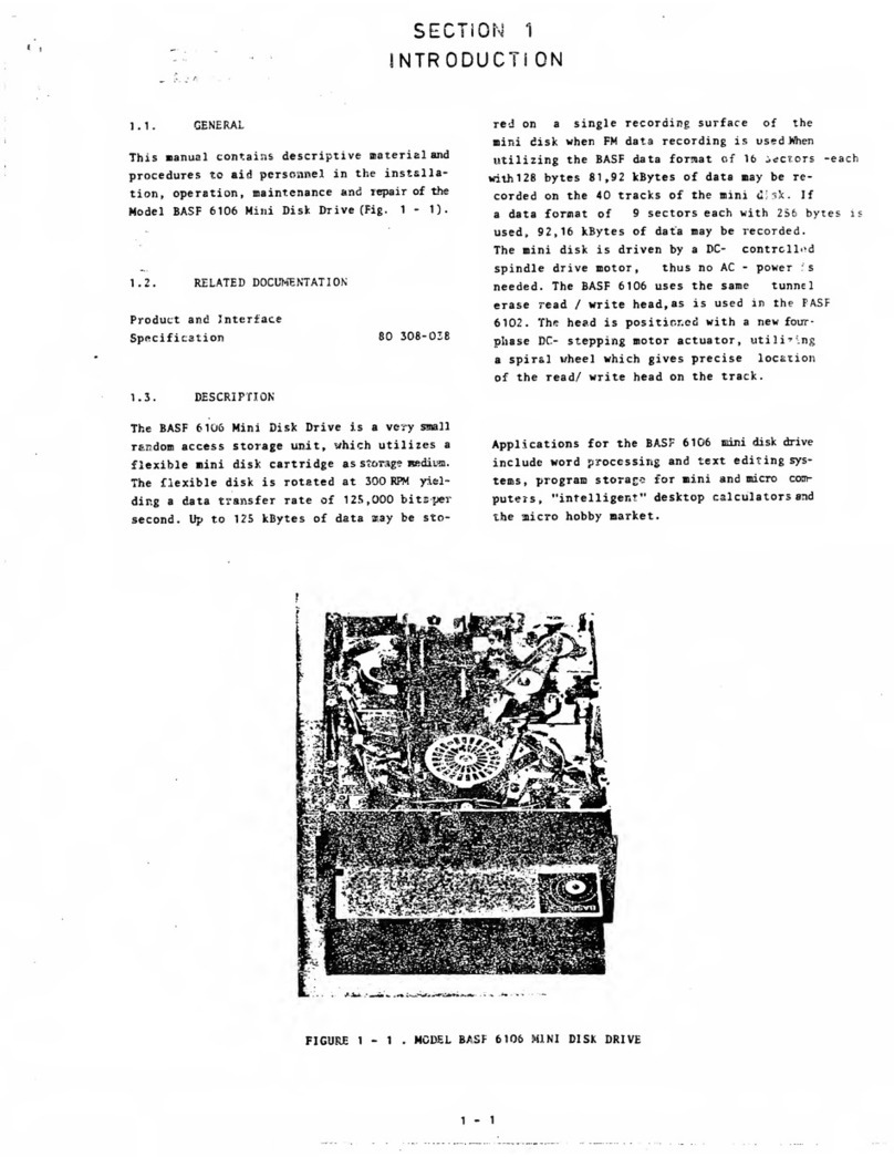
GENERAL
This
manual
contains
descriptive
material
and
procedures useful in
installation,
operation,
maintenance
and
repair
of the
BASF
Mini
Disk
Drive
Models
BASF
6106
and
BASF
6108.
1.2
RELATED
DOCUMENTATIDN
Product-
and
Interface
Specification
BASF
6106/6108
80
307-046
1.3
DESCRIPTION
The
models
BASF
6106
and
BASF
6108
are very
compact
random
access data storage
units,
which
utilize
a 5.25" Flexy
Disk
as
storage
medium.
The
BASF
6106
stores
data
on
one
side
of the Flexy Disk,
the
BASF
6108
on
both
sides.
The
Flexy
Disk
is
rotated
at
300
RPM
yielding
a data
transfer
rate
of
125~000
bits
per second
in
single
density.
Up
to
125
kbytes of
raw
data
may
be
stored
on
a
single
recording surface in
single
density,
and
twice
as
much
in double
density.
Data
capacity
on
all
40
tracks varies
from
81.92 kbytes
(BASF
6106,
16
sec
tors
at
128
bytes)
to
368.64 kbytes, so increasing capacity
more
then four times
by
using the
BASF
6108
with
9
sectors
of
512
bytes each.
The
mini
disk drives are equipped with a
DC-
controlled
spindle drive motor, thus
no
AC-Power
is
needed.
Ceramic
read/write heads with tunnel
erase are
used
with-in
the
BASF
6106/6108
to
ensure
reliable
data recording.
The
heads are positioned with a fourphase
DC-
stepper
motor
actuator,
utilizing
a
spiral
wheel
which
provides precise location of the read/write
head
or heads
on
the
track.
Applications for both types of
mini
disk drives
comprise
word
processing
and
text
editing
systems,
program
storage for
mini
and
micro computers,
"inte
11
igent" desktop ca1
cu
1ators
and
the
hobby
micro computer market.
FIGURE
1 - 1
MODEL
BASF
6106/6108
MINI
DISK
DRIVE
1 - 1

1.4
SPECIFICATION
SUMMARY
Acomprehensive
list
of principa1
specifications
for
model
BASF
6106
and
model
BASF
6108
is
provided
in tab1e 1 - 1.
PER
F 0 R
MAN
C E S P E C I F I C AT
ION
S
CAPACITY
BASF
6106
(single
sided)
Unformatted Single Density
per
Disk
125
kilobytes
per Surface
125
kilobytes
per Track 3.125 kilobytes
Formatted
(16
Sectors/Track)
per
Disk
per Surface
per
Track
per
Sec
tor
TRANSrER
RATE
LATENCY
Maximum
Average
ACCESS
TIME
81.920 kbytes
81.920 kbytes
2.048 kbytes
128
bytes
125
kilobits/s
200
ms
100
ms
Track
to
track positioning
12
ms
Average
240
ms
Settling
Time
max.
48
ms
Head
Load
Time
max.
35
ms
Drive
Motor
Start
Time
max.650
ms
Doub
1eDens
ity
250
kilobytes
250
kilobytes
6.250 kilobytes
163.840 kbytes
163.840 kbytes
4.096 kbytes
256
bytes
250
kilobits/s
F U " C T
ION
A L S P E C I F I C A T
ION
S
BASF
6108
(double sided)
Single Density
Doub
1eDen5
ity
250
kilobytes
500
kilobytes
125
kilobytes
250
kilobytes
3.125 kilobytes 6.25 kilobytes
163.840 kbytes 327.680 kbytes
81.920 kbytes 163.840 kbytes
2.048 kbytes 4.096 kbytes
128
bytes
256
bytes
125
kilobits/s
250
ki10bits/s
BASF
6106
BASF
6108
Single Density
Rotationa1
Speed
300
RPM.:!:.
2,5 %
Recording Density
3979
BPRAD
( inside Track)
(2768
BPI)
Flux
Densitv
7958
FTPRAD
(5536
FCI)
Track Density
48
TPI
Track Radius
Track 00 57,15
mm
Track
39
36.5125
mm
Encoding
Method
FM
Media
Requirements
BASF
F1exy
Disk
5.25"-1
+)
On
Side 1, Side 0 see
6106
Track
radius 1 is 2.
1167
mm
smaller then track radius
O.
Double
Density Single Density
Double
Density
300
RPM
.:!:.
2,5 %
300
RPM
.:!:.
2,5 %
300
RPM
.:!:.
2,5 %
7958
BPRAD
3979
BPRAD
7958
BPRAD
(5536
SP!)
(2768
BP!)
(5536
BP!)
7958
FTPRAD
7958
FTRAD
7958
FTPRAD
(5536
FCI)
(5536
FC!)
(5536
Fe
I)
48
TPI
48
TPI
48
TPI
+) +)
57,15
mm
55,03
mm
+) 55.03
mm
+)
36.5125
mm
34.3958
mm
34.3958
mm
MFM
FM
MFM
BASF
F1exy
Disk
BASF
F1exy
Disk
BASF
F1exy
Disk
5.25"-10 5.25"-2 5.25"-20
lABLE
1 - 1
SPECIFICATION
SUMMARY
(continued)
1 - 2

P H Y S I C
ALS
P E C I F I C A T
ION
S
Environmental
limits
Ambient
temPerature
on
disk surface (operation)
Relative humidity
Maximum
wet
bulb
DC-voltage requirements
Power
dissipation
Mechanical dimensions:
Width
Height
Depth
Wei
ght
R E L
lAB
I L I T Y
MTBF
Unit
life
time
MTTR
Error
rates:
Soft read
errors
Hard
read
errors
Seek
errors
S P E C I F I C AT
ION
S
ME 0
lAS
P E C I F I C AT
ION
S
10
0
to
50
0C
(50
0F to
120
0
F)
20
%
to
80
%
29
0C
(84
0F)
+
12
VDC
+ 5 %
+ 5
VDC
+ 5 %
0,7
A+)
max.
100
mVpp
ripple
0,5 A
max.
50
mVpp
ripple
+)
motor
starting
current
max.
0.65 Afor
max.
50
msec
head
load
start
current
0.7 Afor
50
msec
10.0
Watts
operating
4.0
Watts
stand
by
(motor
off)
7.5
Watts
motor
on
and
deselected
146.1
mm
(5.75 inch)
53.5
mm
(2.11 inch)
19o.o
mm
(7.48 inch)
1.4
kg
10000
POH
under typical usage+)
5 years
30
minutes
1 per
10
8
bits
read
1 per
10
11
bits
read
1 per
10
6 seeks
+)
Duty
cycle of Spindle Drive
Motor:
~%
of
POH
Jacket 133.3
mm
(5.25 inch) square
Disk
130.2
mm
(5.125 inch) diameter
Center hole 28.57
mm
(1.125 inch) diameter
TABLE
1 - 1
SPECIFICATION
SUMMARY
1 - 3

1.5
OPTIONS
SUMMARY
The
following
tables
list
the options of the
ßASF
6106
and.
ßASF
6108
Mini
Disk
Drives.
1.5.1
FACTORY
INSTALLED
OPTION
Option Function
Door
Lock
Lacks
the fant door under
Solenoid control of the users
soft-
ware.
TAßLE
1 - 2
FACTORY
INSTALLED
OPTION
1.5.2
JUMPER
OPTIONS
The
following options are
selectable
by
jumpers
on
the
PCß.
Refer to Table 3 -
10
for
jumper
option matrix.
Option
RADIAL
SELECT
AUTO
SELECT
HEAD
LOAD
IN
USE
Function
Allows
the connection of
three
mini
disk drives to
the hast system.
Each
drive
has
its
own
address (0,1,2)
selectable
by
jumper.
The
interface
is
always
enabled (drive
is
always
selected).
The
SELECT-lines
are not
used.
Loading
of the
head
can
be
accomplished in three
modes:
• Selected
Head
Load
(INT.SELECT-
HEAD
LOAD)
•
Auto
Head
Load
(INT.
SELECT)
• Radial
Head
Load
(HEAD
LOAD)
The
head
will
be
loaded only
if
the inserted
mini
disk
rotates.
Pin
34
of the
interface
is
used
as
IN
USE
input signal
and
controls the
door
lock
solenoid
and
the
activity
indicator.
If
this
option
is
used
the
disk change option
must
be
disabled.
Option
OOOR
LOCK
LATCH
OISK
CHANGE
ODOR
LOCK
ACTI
V
ITY
INOICATOR
OPTIONS
WRITE
PROTECT
OPTION
STEPPER
MOTOR
SWITCHING
Function
Allows
locking of the door
withoui maintaining the
IN
USE
signal activated
by
storing
the
state
of the
IN
USE-signal
into
the
IN
USE-
flipflop.
Ta
use
this
option
the
IN
USE-option
must
be
jumpered.
Notifies the hast system
that
the
mini
disk
has
been
changed.
If
this
option
is
used, the
IN
USE-option
must
be
disabled.
Locking
of the door
can
be
accomplished
as
follows:
1.
by
the
IN
USE-signal
2.
by
the
IN
USE-FF
(ODOR
LOCK
LATCH)
3.
if
the drive
is
selected
(1/0
ENA
activ)
4.
if
the
head
will
be
loaded
(HOLOADENA
activ)
5.
if
1.
or 3.
is
true
6.
if
l.
or 2. or 3.
is
true
7.
if
l.
or 4.
is
true
8.
if
1. or 2. or 4. is
true
The
lighting
of the
activity
LED
is
selectable
by
jumper
to
one
of the following
conditions:
• the
head
is
loaded
and
the
drive
is
ready
• the
door
is
locked
and
the
drive
is
ready
Allows
protection of the
mini
disk against overwrite
if
the write
protect
notch
is
closed
(ECMA,
Shugart).
The
stepper
motor
is
switched
on
.nd
off
together with the
drive
motor
if
a jumper
is
in-
serted.
If
the
jumper
is
not
inserted,
the stepper
motor
will
be
enabled
as
lang
as
power
is
supplied.
TAßLE
1 - 3
JUMPER
SELECTAßLE
OPTIONS
1 - 4
i
/

1.6
RECORDING
MEDIA
The
BASF
mini
disk drives
use
a removable
130
mm
(5.25 inch) diameter
flexible
disk
as
storage media. Fig. 1-2
shows
'construction
and
dimensions of a
typical
5.25" Flexy Disk.
The
recommended
recording
media
is:
formodel
BASF
6106
mini
disk drives:
single
dens
ity:
double density: 5.25"-1
5.25"-1 D
for
model
BASF
6108
mini
disk
drives:
single
density:
double density: 5.25"-2
5.25"-2 D
The
Flexy
Disk
is
an
oxide coated
flexible
disk enclosed in a
protective
plastic
envelope.
The
protective
envelope contains
apertures
for
head
contact,
index
detection,
write
protect
detection
and
drive spindle
loading.
The
write
protect
notch
is
used
to
protect
the
written
data
on
the Flexy
Disk
(see
2.2.6
Write Protect Detector).
St:ALEIl
t'Kon:CTI
vt:
.lACKET
SI'
1NOLEI
111111
.\t,U:SS
__
----133,3
81111
R I
I"'l./
~
\
/
r
HYLAR
OlSK
TRACK
00
/
FIG.
1 - 2
/'
/"
---
.......
........
Q)
/\,./
__
---;.~_lNDEXI
SECTOR
IIOLE
-
LINER
/
/"
FLEXIBLE
DISK
CONSTRUCTION
AHD
DIMENSIONS
lNDEX
HOLE
TRACK
39
1 - 5
1.7
RECORDING
FORMATS
The
format of the data recorded
on
the
diskette
depends
on
the host system. There are
two
encoding
schemes
used:
•
FM
(Frequency
Modu
1ati
on)
for
single
density
•
MFM
(Modifieo Frequency Modulation)
for double density.
1.7.1
FM-ENCODING
This
scheme
utilizes
clocks
to
define
bit
cell
times.
The
presence of a flux reversal
between
clock pulses i5 defined
as
a "one"
bit.
The
absence of a flux reversal
between
clocks
is
defined
as
a "zero"
bit.
On
the write data
and
read data
interface
lines
between
disk drive
and
host system every pulse represents a flux
re-
versal
on
the
diskette.
8 jJsec
BITCELL
~-I
, i
OATA
I' I'I ' 10 I ' I0 I 0 I0 I'I
I I I I I I 1 I 1 I
I I
l-j8jJ
s
t-
I I I I I
Il4jJ~11111111
I
lir:
I 1 I 1 I I
WRITE
OATA
I1IIIII
'al
•I
'a'
COCOCOC
COC C c
eoc
FIG.
1 - 3
FM-ENCODING
1.7.2
MFM-ENCODING
Aflux
transition
is
always
recorded
at
the center
of the
bitcell
for
each
Hone"
data
bit.
No
flux
transition
is
recorded for a "zero"
bit
unless
it
is
not followed
by
another "zero"
bit.
In
this
case the flux
transition
is
provided
at
the
end
of the
first
bit
cel,o
4 jJsec
BITCELL
DATA
l,h
tj
01
1
10
10 10
I'
I
I I I I I I
I I I
f'S~f'S~
I I
I I I I I -t4jJSl-- I
WRITE
OITIl.
I , , I ,
o 0
FIG.
1 - 4
MFM-ENCODING

1.8
TRACK
FORMAT
The
tracks
of the
F1exy
Disk
may
be
formatted
in
numerous
ways,
depending
on
the formatter
of the host system used.
The
BASF
mini
disk
drives
write
and
read hard or
soft
sectored
track formats.
1.8.1
SOFT
SECTORED
TRACK
FORMATS
In
a
soft
sectored track format the user
may
record
one
10ng
record or severa1
sma11er
records
on
a
track.
The
most
common
soft
sectored track formats are described in
the
fo110wing
chapters.
(The
designer should also consider national
and
international
standards for data
inter-
change ).
1.8.1.1
SOFT
SECTORED
TRACK
FORMAT
FOR
SINGLE
DENSITY
(16
sectors/track
ä
128
bytes)
This format
is
shown
in Fig. 1-6.
It
is
similar
to
the
IBM-format.
The
beginning of a track
is
indicated
by
a
physical index pulse.
Every
record
is
pre-
ceded
by
a unique record
identifier.
Record
identifiers
and
data fie1ds are separated
by
gaps.
The
gaps
are necessary to allow updating
of a data fie1d without disturbing adjacent
fie1ds.
INDEX
GAP
This
gap
starts
with the index pulse
and
is
16
bytes in 1ength.
It
is
not
affected
by
any
update
write
process.
IDENTIFIER
GAP
This
gap
consists
of
11
bytes
FF
and
may
vary
slightly
in
length
after
the
data
field
has
been
updated.
DATA
GAP
This
gap
separates the data
fiel
d
from
the
fo110wing
ID-fie1d
and
is
nominal1y
27
bytes
in 1ength.
It
will vary
slightly
in
length
after
the data fie1d has
been
updated.
TRACK
GAP
The
gap
between
the
last
data fie1d
and
the index
pulse
is
defined
as
Track
Gap.
It
varies
slightly
in 1ength.
due
to
write freqyency
and
disk speed
tolerances.
It
is
nomina1ly
101
bytes in length.
ADDRESS
MARK
(AM)-BYTE
The
soft
sectored track format needs unique
bit
patterns
to
identify
the beginning of
ID
and
Data
Fie1ds
for
synchronizing
the
deserializer
circuit
in the host system.
The
unique
bit
pattern
is
ca1led Address
Mark
(AM).
AM-patterns
do
not
contain clock
bits
in
all
bit
cells
(allother
data bytes
must
have
c10ck
bits
in every
bit
cell!).
There are three
different
AM-patterns used:
•
ID-AM
•
DATA-AM
•
DELETED
DATA-AM
in
front
of
an
ID-Field
in
front
of a
Data
Fie1d
in
front
of
aDeleted
Data
Field
I
BYTE
10
-AM:
f7SC
6 C
s C4 C
3 S
C,
.~
8
••
,., ,., ,.,
•I ••
SEI'
CLOCK
(C7)
" "
..
,
,.
..
"
08
°7
°6
Os
°4
0)
Ll.!
SEP
DATA
(FE)
I I I I I I I
DATA
-
AM:
I
Ir
C7 C
6 Cs
C4
c)
I
1'8 r2
CI
IS
I I
,.,
....
.,
••I I
SEP
CLOCK
(Cn
J;
..
I,
II
..
08 07 06
05
If.
°2 ,
°ll
SEP
DATA
(F8)
I'
I I I I I I:
I
I I
DUETEn
DATA
-MI: I
fll
C7
c,.
C5
Cf.
C)
'2
CI
le
8
I I
,.,
,.,
1"\ I I I •
SEP
CLOCK
(c1)
I.
" "
,
Ir
A,
Os
0,
°6
Os
()4
!lEP
DATI.
CFS)
I I I I I
FIG.
1 - 5
ADDRESS
MARK
PATTERNS
1 - 6

SECTOR
IDENTIFIER
The
sector
identifier
consists
of the
identifier
mark, the address
identifier
and
the
EOC
pattern.
IDENTIFIER
MARK
This
field
comprises 7 bytes (see Fig.
1-6).
The
6 bytes
of
zeros in
front
of the address
mark
byte are for synchronisation of
the
data
separator in the host system.
The
ID-AM-byte
contains a data
pattern
of
FE
where
the clock
bits
C6,
C5
and
C4
are missing as explained
before.
AOORESS
IDENTIFIER
The
address
identifier
comprises the following
6 bytes:
TRACK
ADDRESS
(TRK)
This byte represents in binary notation the
track address
from
00
for
the outermost track
to
39
for the innermost
track.
SIDE
ADDRESS
(SID)
Represents in binary notation
the
sioe
address
(00
or
01)
of the
mini
disko
SECTOR
ADDRESS
(SEC)
Represents in binary notation the
sector
address
from
01
for
the
1st
sector
to
16
for the
last
sector
of a
track.
SECTOR
LENGTH
(LEN)
This byte
identifies
the length of the data
field
as
follows:
00:
128
bytes
01:
256
bytes
02:
512
bytes
03:
1024
bytes
EDC-BYTES
(EDC)
These
two
bytes are hardware generated
from
the
host system
by
shifting
serially
the
bits
of the
sector
identifier
starting
with
the
ID-AM
and
ending
with the 4th byte of the
sector
identifier
through
a
16-bit
shift
register
described
by
the generator
polynominal :
(For
more
details
read chapter EDC-implementation!)
SECTOR
IOENTIHER
IDF.NTIFIER
GAP
FIRST
DATA
BLOCK
OATA
BLOCK
GAP
LAST
OATA
BLOCK
OATA
BLOCK
GAP
13
BYTES
11
X
FF
137
BYTES
27
X
FF
137
BYTES
27
X
FF
1
si
:öector
j--1-
BIDEX
PULSE
V,C
6
I
BYTE
'i
ls
SECTOR
IDE~TIFIER:
ID
-
AM:
Cs C4 S S
I I n "
...
I I I I
sn
CLOCK
(c7)
11
"
..
, ! ,
I.
"
OB
°7 06 05 04
°3
l2
SEP
OATA
(FE)
I I I I I I I
'--v---J
ID-AH
I
I
DATA
BLOCK:
DATA -AM: I I
'C C7 C
6 Cs
C.
C3
'2
C,
~
,8
S
DATA
FIELD
I 2 8 B Y T E S
I I "
...
" I 1 I I
SEI'
CLOCK
(C7)
I:
"
I.
II
II
De
D7 D6 Os
D2
I
1.\
01.
SEP
OATA
(FB)
I I I I 1 I
I:
~
,
DATA-AH I
I
I
I ) OATA
PATTERN
• I
DELETED DATA -
AH:
I
2)
CLOCK
PATTERN
•
OELETEO
AM
pS
f'8
C7
ct.
Cs
Cf,
C3
<lz
CI
le
S
1 I n
...
i1
1 1 1 •
SEP
CLOCK
(c1>
11
..
I,
,.
DS
0]
D6
DS
D.
SEP
DATA
(FS)
1 I I I I
FIGURE
1 - 6
SOFT
SECTORED
TRACK
FORMAT
WITH
16
SECTORS/TRACK
FOR
SINGLE
DENSITY
(FM)
1 - 7

DATA
BLOCK
The
data block contains
the
data mark, the data
fie1d
and
the
EOC-bytes.
DATA
MARK
This fie1d comprises 7 bytes (see Fig.
1-6).
The
6 bytes of zeros in
front
of the data
address
mark
are for synchronisation of the
data separator
circuit
in
the
host system.
The
data address
mark
byte contains
FB
in
front
of
anormal data fie1d.
When
adeleted
data fie1d
fo110ws,
F8
must
be
written.
The
c10ck
pattern
of the data address
mark
is
C7
(C6,
C5
and
C4
missing) .
DATA
FJELD
This fie1d comprises
128
bytes.
If
it
comprises
1ess than
128
bytes, the remaining
positions
sha11
be
fi11ed with zeros.
EDC-BYTES
These
two
bytes are hardware generated
by
the
host system
by
shifting
seria11y the
bits
of
the
data block
starting
with the
Oata-AM
and
ending with the
last
byte of the data fie1d
I'\..
!cl
I----I~--
through a
16-bit
shift
register
described
by
the
fo11owing
generator polynominal:
EOC-IMPLEMENTATION
Fig. 1-7
is
a simp1ified 10gic
of
a
shift
register,
which
may
be
used to generate the
EOC
bytes.
Prior
to
the operation,
all
positions
of the
shift
register
are
set
to
ONE.
Input data are
added
(exc1usive
OR)
to the contents of
position
C
15
of
the
register
to
form
a feedback. This feedback in
turn
is
added
(exc1usive
OR)
to
the contents of
position C
4
and
position C
11
.
On
shifting,
the outputs of the exc1usive
OR
gates
are entered
into
positions
CO'
C
5
and
C
12
respec-
tive1y. After the
last
data
bit
was
added, the
register
is
shifted
once
more
as
specified
above.
The
register
then contains the
EOC
bytes.
When
further
shifting
is
to take p1ace during the writing
of the
EOC
bytes, the contro1 signal
inhibits
ex-
c1usive
OR
operations.
To
check
for
errors
when
reading, the data
bits
are
added
into
the
shift
register
in exact1y the
same
manner
as
they
were
during
writing.
After the
data the
EDC
bytes are also entered
into
the
shift
register
as
if
they
were
data.
After the
final
shift,
the
register
contents
will
be
all
ZERO
if
the record
does
not contain
errors.
eONTROL
OUTPUT
tor
EDe
writing
INPUT
FIGURE
1 - 7
SIMPLIFIED
EOC
SHIFT
REGISTER
1 - 8

1.8.1.2
SOFT
SECTOREO
TRACK
FORMAT
FOR
SINGLE
OENSITY
(9
SECTORS/TRACK
ä
256
BYTES)
In
this
format,
which
is
shown
in
Fig. 1-8,
each
sector contains
256
bytes.
I
1----------
Ist
SECTOR
.r--L
x + Y + Z •
204
BYTES
INDEX
PULSE
SECTOR
IDE~TIFIER:
L-.---J
ID-AM
DATA BLOCK:
DATA
FIELD
2 5 6 B Y T E S
~
DATA-AM
I )
DATA
PATTERN
2)
CLOCK
PATTERN
• DEUTED
AM
Fa
LAST
DATA
BLOCK
DATA
BLOCK
GAP
256
BYTES
(32+Y)
X
FF
9th
SECTOR
--I
10
-AM:
sn
CLOCK
(C7)
SEP
DATA
(FE)
OATA -AM: I
Ic C7 C6 Cs c4 C3 '2
I 8
I I
,.,
,.,
'1
I I
SEP
CLOCK
(C7)
I: " "
..
I.
Da
D7 D
6 D
s
Pt.
D2
SEP
DATA
(FB) I I I I 1 I
I
DELETED DATA -
AH:
~
C7
Ce
Cs
Ct.
C3
C2
1 I n
..,
..,
1 I
SEP
CLOCK
(c1>
' ,
I,
'I
.. ..
..
D8
D7
D6
DS
D4
SEP
DATA
(F8) I I I I I
FIGURE
1 - 8
SOFT
SECTOREO
TRACK
FORMAT
WITH
9
SECTORS/TRACK
1 - 9
I
I
CI
~8
I I
I
DI
I
I:
I
I
I
I
CI
IC
1
.8

1.8.1.3
SOFT
SECTORED
FORMAT
FOR
DOUBLE
DENSITY
(16
Sec
tors
a
256
bytes)
On
double sided
diskettes
for double density
track 0
on
side 0
is
recorded in
FM.
For
this
track only the previous described track
format for single density
is
valid.
All
other
tracks
on
the
diskette
are recorded in
MFM.
Far these tracks the following track format
will
be
valid (see Fig. 1-9).
The
content of the data blocks
is
doubled to
256
bytes.
In
MFM
recording the
bit
density
is
also doubled. the
sector
count will
be
the
same
as
in
single
density format (1.B.1.1).
The
meaning
of the
different
fields
a~ the generation of the
EDC-bytes
are the
same
as
in single density re-
cording.
Only
the address
mark
pattern
is
changed
as
shown
in Fig. 1-9.
INOEX GAP
so
x
I.E
12
•
00
3.
C2
1)
IFC
150
dE
11
MI551NG
CLOCK
TRANSITIONS BETWEEN
BITS
S ANO
l..
----::::_-'--
-
1
____
_
I
-_
---
__
_
I
--_
--_
t---
1
BYTE----i
'
---
-----
I C2 1
C2
C2
---
FC
----
11
11
101010
101
1
10
11
11
10
1010
10 11 10
11
11
101010
101
1
I"J
1 11 11
11
11 11
101
rJl
INOEX -AM
Os
07
Cs
CL
C3
02
OB
07
Cs
CL
C3
02
Os
07 Cs
CL
C3
02
Da
~
CI:,
Dt.
D:J
02
Cl
Cs
I I I n I I I I I n I I I I I n I I I I I I I I I I
SECTOR
10ENTIFIER
71
MISSING CIOCK TRANSITIONS BE TWEEN BITS 4
ANO
3
10-AM·
1
-~----
I
----:::----
___
_
I
Al
Al
Al
---
f'E
---:-\
11101110101010111'10111010101:'1111101110101010111'11111111111110,
Os
05
CI.
C3 C2
0,
Os
05
CI.
C3
C2
01
Os
0"
CI,
C3
C2
01
Os
07
Cf;
Os
01.
03
02 Ca
I I
Inlll
I
Inl
I1
I
Inl
.11111111
OATA BLOCK
OATA
-AM
OATA
FIELO
255
BY
rES
2)
MISSING
CLOCK
TRANSITIONS
BETWEEt~
BITS
4 ANO
3.
110ELFTFU
RFCORO
FB
I
--------
I
----.-------
--
--
--
I
--__
---
__
I
Al
Al
Al
--
FB
---_
1'10IlI01010101111101'101010101,1'10ilI0IUI010~'I'I'I'111011111
.
lOs
06
CL
C3
C2 01
08
Dr;
CI,
C3
(7
01
1lfl llr,
CI,
[3
C7
III lltj
11'1
lle,
Os
111.
07
U,
11
I I n I I I I I nI I I I I n I I I I I I I I I
I
I
I
1
OELETED
OATA-AM.
Al
Al
Al
FS
1110111010101011111011101010101111101110101010111,111111111010101
OB
I
FIGURE
1 - 9
SOFT
SECTORED
TRACK
FORMAT
FOR
DOUBLE
DENSITY
(MFM)
1 - 10

2.1
FUNCTIONAL
OESCRIPTION
The
models
6106
and
6108
comprise the following
mechanisms
and
functional
circuits
(see Fig. 2 -
1).
Functional
Circuits:
•
Interface
• Drive
Motor
Control
Mechanisms:
•
HEAD
LOAD-,
OOOR
LOCK-
and
ACTIVITY
LEO-
Driver
• Drive
Mechanism
•
Track
Zero
Detector
• Spindle
and
Front
Ooor
Mechanism
• Write Protect Oetector
• Positioning
Mechanism
•
Index
/
Ready
Oetector
•
Head
Load
Mechanism
•
Read
/ Write
Circuits
•
OC-
Control
and
Power
On
Reset
LOGIC
SELEC
T
11
SELECT
21
SELECT
31
_
WRITE
DATA
I
WRITE
GATE!
SIDE
SfLHTI
I
N
P
U
T
o
IRECTION
/NI
STEPI
I
N
T
f
R
F
A
C
IN
USE
I
(oploona
11
E
HEAD
LOADI
MOTOR
ON
I
•
SIOE
SELECT
LOGIC
UD
E
NA
WRITE INHIBIT
R(ADI
I-f--~
WRITE
WRT
(URRENT
or
RD
PLAYBACK
CIRCU
ITS
[RASE
H--""I
(URRENT
SIDf
HI-_-=S:;.:ID:..:E=--.:I
_____
""I
SELE
er
LOGIC
PHASE
1
S
TEPPER
~I---<-t
MO
TOR
~I----<_
(ONTROL
3
4
~:dnCT
~rgS~R
ODOR
LOCK
SENSOR
~
~LENOID
0 \
~
snPPER
MOTOR
I
~:-..
(<I
~
ZERO
L.
I ....
~
LIGHT-
TRACK
ZERO
ETECTOR
I,pl"~,,
i
"L1~1~IT\:~
~I
~~
r,
~TRACK
ODOR
LOCK
OOOR
LOCK
I
....
NN
~-
_~RIER...NC
'--
ENA
ANO
~
~
~I.ft
AUIVI
TY
~~-
()!:!.I.!...--C':':':::"::.J
IEAO
LOAD
DRIVER
R/W
[NA
HEÄÖ--
HEAO
0
-MOTOR
~
~~~SER
HEAD
LOAD
SOLENOID
DRIVE
HH_""I
MOTOR
(ONTROl
f--
INDEX
J
READY
L-----------I
OETE
(TOR
INDEX
WRT.
ERASE
CURRENT
•
sv
oc
•
12V
oe
1
CJl~ROL
AND
POWER
ON
RESET
L-
____________
~
WRITE
PWR
ON
RESET
PROTECT
OETHTOR
FIGURE
2 - 1
BLOCK
DIAGRAM
BASF
6106/6108
2 - 1
I
E
ADY
o
U
T
P
U
T
I
N
T
f
R
F
A
(
E
REAO
DATA
I
TRACK
OQl
INDEXI
_
READYI
D
ISI<
CHANGEI
(optlon~11
WR
ITE
PROTECTI

2.1.1
DRIVE
MECHANISM
The
spindle
is
rotated
at
300
rpm
by
a
DC
drive
motor. Rotation of the spindle
is
provided
by
a
belt
and
pulley.
The
drive motor
is
started
and
stopped
by
the
interface
signal
MOTOR
ON.
The
ratio
between
motor
and
spindle speed
is
approximately 7:1.
The
drive
mechanism
is
shown
in Fig. 2 - 2.
2.1.2
SPINDLE
AND
FRONT
ODOR
MECHANISM
The
main
parts
of
this
mechanism
are
the
drive
hub, the centering cone, the centering cone
expander
and
the
front
door with pressure
arm
and
door
latch
(see Fig. 2 -
3).
For
loading,
a
diskette
is
inserted
and
the
front
door
pressed.
The
pressure
arm
moves
down,
the
centering cone
enters
the Flexy Disk.
Just
before the centerlng cone reaches
the
full
down
position,
the
centering
cone
expander
is
FRONT
OOOR
(closed)-----1'.
DOOR
LATCH
DRIVE
MOTOR
SPINDLE
DRIVE
PULLEY
FIGURE
2 - 2
SPINDLE
DRIVE
HUB
DRIVE
MECHANISM
activated
and
expands the centering
cone
which
grips
the inner diameter of the Flexy
Disk
to
ensure
correct
alignment.
The
door
latch
is
activated
and
holds the
front
door in a closed
position.
For
un.loading a disk,
the
front
door
must
be
pressed again.
The
door latch
opens
and
the pressure
arm
is
moved
upwards
by
aspring.
The
centering
cone
and
centering
cone
expander also
move
upwards
and
disengage
the
mini
disk
from
the drive
hub.
PRESSURE
ARM
? - 2
CESTERING
CONE
EXP~~DER
I
CENTERING CO:\[
I
I
!
I
DRIVE
Hl'B

2.1.4
HEAD
LOAD
MECHANISM
The
head
load
mechanism
comprises
(see Fig. 2 - 5):
•
Head
Load
Solenoid
•
Head
Load
Actuator
HEAD
LOAD
PRESSURE
ARM
R/W
HEAD
HE
AD
LOAD
PAD
HEAD
LOAD
ACTUATOR
HEAD
LOAD
SOLENOID
R/W
HEAD
0
R/W
HEAO
1
When
the
head
load solenoid
is
energized,the
head
load
actuator
releases
the
head
load pressure
arm
of the
carriage
assembly.
On
the
single
sided
mini
disk drive
(BASF
6106)
this
causes the
mini
disk to
be
pressed
against the
read/write
head
by
the
head
load pad.
On
the
double sided
mini
disk drive
(BASF
6108)
the
F1exy
Disk
is
pressed against the bottom
head
(HEAD
0)
by
the upper
head
(HEAD
1)
mounted
in the pressure
arm.
The
pressure
foam
on
the
head
load
actuator
stabi1izes
the
F1exy
Disk.
When
the
head
load solenoid
is
deener-
gized,the
head
load actuator
is
1ifted
by
aspring.
The
head
load pressure
arm
is
lifted
also.
FIGURE
2 - 5a)
HEAD
LOAD
MECHANIS~l
BASF
6106
FIGURE
2 -
Sb)
HEAD
LOAD
MECHANJSM
BASF
6108
2 - 4
\

2.1.3
POSITIONING
MECHAHIS~
The
main
parts
of the
positioning
mechanism
are (see Fig. 2 - 4):
• Stepper
Motor
•
Spiral
Wheel
• Carriage
Assembly
The
stepper
motor
is
a four phase motor
and
1S
rotated
150
by
every
step
pulse.
The
spiral
wheel
directly
connected
to
the
shaft
of
the
stepper
motor converts
the
rotational
motion of
the
stepper motor
to
a
linear
motion of
the
read
write
head
assenbly.
GUIDE
BARS
R/W-HEAD
The
BASF
6106
carriage
assembly (Fig. 2 - 4a)
consists
of
the
read/write
head.
and
the
head
load pressure
arm.
The
read/write
head
is
inserted
in
the
carriage
assembly,
which
rides
on
two
guide
bars.
The
Flexy
Disk
is
pressed
against
the
readl
write
head
by
the head load pressure
arm.
The
head
load pressure
arm
is
released
by
the
head load
mechanism.
In
the
BASF
6108
carriage
assembly (Fig. 2 - 4b)
the head load pressure
pad
is
replaced
by
the upper
read/write
head.
HEAD LOAD
PRESSURE
ARM
STEPPER
MOTOR
SHAFT
FIGURE
2 - 4
a)
POSI
rIONING
MECHANISM
BASF
6106
R/W-HEAO
0
(BUTTON
TYPE)
R/W
HEAD 1
(CA
TAMARAN
TYPE)
~~:jJ
FIGURE
2 -
4b)
POSITIONING
MECHANISM
BASF
6108
2 - 3
Other manuals for 6106
2
This manual suits for next models
1
Table of contents
Other BASF Floppy Disk Drive manuals
