BASF 6104 LSI User manual

Technical
Manual
4“
x
MODEL
6104
LSI
FLOPPY
DISK
DRIVE
PART
No.
80307-
048
BASF
Aktiengesellschaft
Datentechnik/OEM
Vertrieb
Gottlieb-Daimler-Strafe
10
D-6800
Mannheim
1
Tel.
0621
-
4008380


REMARKS
REVISION
RECORD
OF
REVISION
01
LSI
-
G
VALID
FOR
LSI-VERSION
02
LSI
-
G
CORRECTIONS
03
LSI
-
G
CORRECTIONS


LIST
OF
CONTENTS
I
-
INTRODUCTION
1.1.
1.2.
1.6.
1.7.
1.8.
General
Related
documentation
Description
Specification
summary
-
Options
summary
1.5.1.
Jumper
selectable
options
1.5.2.
Factory
installed
options
Recording
media
Recording
formats
1.7.1.
F
M
-
encoding
1.7.2.
M
F
M
=
encoding
Track
format
1.8.1.
Soft
sectored
track
formats
1.8.1.1.
IBM
format
for
single
density
(FM)
1.8.1.2.
IBM
format
for
double
density
(MFM)
II
-
THEORY
OF
OPERATION
2.1.
2.2.
General
Functional
description
2.2.1.
Spindle
drive
system
2.2.2.
Spindle
system
2.2.3.
Positioning
system
2.2.4.
Heads
load
mechanism
-
Drive
electronic
description
2.3.1.
Block
diagram
2.3.2.
Large
scale
integrated
circuit
BASF
81041-001
2.3.3.
Input
interface
2.3.3.1.
Input
signals
definitions
and
termination
13

Page
2 -
List
of
contents
(continued)
2.3.3.2.
Select
options
2-9
2.3.3.3.
Side
select
options
2 -
10
2.3.3.4.
Head
load
options
2
-
13
2.3.3.5.
Radial
step
option
2-
14
2.3.4.
Output
interface
2-15
2.3.4.1.
Output
signals
definitions
2-15
2.3.4.2.
Options
of
the
output
interface
2
-
16
2.3.5.
Stepper
motor
logic
2-17
2.3.5.1.
Step
control,
step
counter
and
decode
2 -
18
2.3.5.2.
Modes
of
the
stepper
motor
logic
2-
18
2.3.5.3.
Stepper
motor
drivers
2 -
20
2.3.6.
Track
zero
detector
2
-
21
2.3.7.
Index/dual
side
detector
and
ready
monitor
2 -
22
2.3.7.1.
Index/dual
detector
2
-
22
2.3.7.2.
Ready
monitor
2
-
23
2.3.8.
Sector
separator
(Hardsector
option)
and
sector
divider
option
2
-
24
2.3.8.1.
Sector
separator
2 -
24
2.3.8.2.
Sector
divider
option
2 -
24
2.3.9.
Disk
change
logic
2 -
25
2.3.10.
Heads
load, door
interlock
and
activity
led
drivers
2 -
26
2.3.10.1.
Heads
load
driver
2
-
26
2.3.10.2.
Door
lock
and
activity
driver
2
-
26
2.3.10.3.
Door
lock
latch
option
2
-
27
2.3.11.
Side
select
circuits
2
-
28
2.3.12.
Read/write
circuits
2
-
29
2.3.12.1.
Read/write
head
2
-
29
2.3.12.2.
Write
circuits
2
-
30
2.3.12.3.
Auto
erase
option
2 -
32
2.3.12.4.
Write
protect
detector
and
write
protect
option
2
-
33
2.3.12.5.
Read
circuits
2
-
34
2.3.13.
Postcompensation
option
2
-
38
2.3.14.
DC
-
control
and
power
on
reset
logic
2
-
39
2.3.15.
-
5
V_
regulator
2
-
39
2.3.16.
Data
separator
option
2
-
40
we
e/aee

Page
3
-
List
of
contents
(continued)
III
-
INSTALLATION
AND
OPERATION
3.1.
Installation
3.1.1.
General
3.1.2.
Unpacking
and
inspection
3.1.3.
Connecting
cables
3.1.4.
Connectors
3.1.4.1.
AC
-
power
connector
3.1.4.2.
DC
-
power
connector
3.1.4.3.
Signal
connector
3.1.4.4.
Interconnecting
diagram
3.1.5.
Logic
levels
and
termination
3.1.6.
Connecting
configuration
3.1.6.1.
Single
drive
configuration
3.1.6.2.
Multiple
drive
configuration
3.1.7.
Selection
of
the
desired
options
3.1.7.1.
Select
options
3.1.7.2.
Side
select
options
3.1.7.3.
Head
load
options
3.1.7.4.
Radial
step
option
Ww
=
.
~
.
w
-
Radial
ready
option
-1.7.6.
Radial
index/sector
option
-1.7.7.
Hard
sector
and
sector
divider
option
.
Activity
indicator
/
door
lock
options
Ww
WwW
WN
WwW
4
~“s
oo
-1.7.9.
Auto
erase
option
3.1.7.10.
True/false
data
separator
option
3.1.7.11.
-
5
V_
regulator
é
3.1.8.
Drive
mounting
3.1.8.1.
Mounting
positions
3.1.8.2.
Use
of
carrier
springs
3.1.8.3.
Mounting
dimensions
Operation
3.2.1.
General
3.2.2.
Diskette
storage
and
handling
3.2.3.
Diskette
laoding
and
unloading
3.2.4.
Write
protect
ao
un
&
S&
&
16
16
16
16
17

Page
4
-
List
of
contents
(continued)
IV
-
MAINTENANCE
4.1.
4.2.
4.4.
General
Tools
and
test
equipment
.
Preventive
maintenance
4.3.1.
Visual
inspection
and
cleanliness
4.3.2.
Lead
screw
lubration
4.3.3.
Read/write
heads
cleaning
4.3.3.1.
Read/write
heads
cleaning
with
BASF
cleaning
disk
4.3.3.2.
Read/write
heads
cleaning
without
cleaning
disk
Checks,
adjustments
and
replacements
4.4.1.
PCB
replacement
4.4.2.
Spindle
drive
system
4.4.2.1.
Drive
motor
aid
drive
belt
checks
4.4.2.2.
Drive
motor
speed
check
4.4.2.3.
Drive
belt
replacement
4.4.2.4.
Drive
motor
replacement
4.4.3.
Positioning
system
-4.3.1.
Track
adjustment
check
Track
adjustment
oO
An
ann
PWN
.
.
. .
.
Track
zero
switch
adjustment
check
Track
zero
switch
adjustment
.
Track
zero
switch
replacement
Outer
stop
adjustment
check
.
Outer
stop
adjustment
Inner
stop
adjustment
check
Inner
stop
adjustment
PPerr
eK
SR
HE
PPee
He
He
RA
WWWWHNnNnunnyw
-10.
R/W
head
-
carriage
replacement
4.4.4.
Heads
load
mechanism
4.4.4.1.
Heads
load
actuator
check
4.4.4.2.
Heads
load
actuator
adjustment
4.4.4.3.
Heads
load
solenoid
replacement
4.4.5.
Read/write
electronics
4.4.5.1.
Read
amplitude
check
4.4.5.2.
Data
separator
adjustment
check
4.4.5.3.
Data
separator
adjustment
(option)
4.4.6.
Photo
transistor
and
led's
4.4.6.1.
Index
detectors
adjustment
check
4.4.6.2.
Index
detectors
adjustment
>
SOU
SUD
> +
PPP
Phth
ee
PP
HE
PP FH
HHS
+
+
S$
SH
fF
HF HL HS
+>
+
5S
nun
>
-&
W
10
11
12
13
13
14
14
15
16
16
16
16
17
17
17
17
18
18
18

Page
S
LIST
OF
ILLUSTRATIONS
FIGURES
1-1
1-2
1-3
1-4
1-5
1
-
6
1-7
1-8
2-1
2-2
2-3
2-4
2-5
2 -
6
2-7
2-8
2-9
2
-
10
2-11
2-12
2
-
13
2-14
2-15
2
-
16
2-17
2 -
18
2-
19
2
-
20
2
-
21
2
-
22
2
-
23
2
-
24
2
-
25
2
-
26
:
Model
BASF
6104
double
sided
flexy
disk
drive
Flexible
disk
construction
and
dimension
:
FM
-
encoding
:
MFM
-
encoding
Cylinder
and
tracks
Soft
sectored
track
format
for
single
density
(FM)
Simplified
EDC
shift
register
Soft
sectored
track
format
for
double
density
(MFM)
Positioning
system
and
heads
load
mechanism
Block
diagram
BASF
6104
LSI
Input
signal
termination
:
Radial
select
option
Binary
select
option
Side
selection
using
the
side
select
signal
Side
selection
by
step
in
Side
selection
using
the
select
lines
and
radial
select
:
Side
selection
using
the
select
1/
line
and
binary
select
:
Select
heads
load
:
Auto
heads
load
Radial
heads
load
Radial
step
option
Radial
index/sector
option
:
Block
diagram
stepper
motor
logic
Stepper
motor
timing
for
1
of
4
phases
on
with
overlap
(standard
configuration)
Stepper
motor
timing
for
1
of
4
phases
active
:
Stepper
motor
timing
for
2
of
4
phases
active
:
Stepper
motor
timing
for
1
of
3
phases
active
:
Stepper
motor
driver
circuit
:
Track
zero
detector
Index
and
dual side
detector
Ready
monitor
Ready
timing
Sector
separator
and
sector
divider
option
:
Timing
diagram
index
-
hard
sector
and
sector
divider
options
PAGE
uo
Oo
oO
DO
Ff
10
10
11
12
13
13
13
14
16
17
19
19
19
20
20
21
22
23
23
24
24

Page
6
-
List
of
illustrations
(continued)
FIGURES
2
27
2
28
2
29
2
30
:
2
31
2
32
2
33
2
34
2
35
2
36
2
37
2
38
2
39
2
40
:
2
41
2
42
2
43
2
44
2
45
2
46
2
47
2
48
2
49
2
50:
2
51
2
52
3
1
3
2
3 3
3 4
3
5
3
6
3
7
3
8
3
9
3
10
:
3
11
3
12
3
13
3
14
Disk
change
logic
:
Timing
diagram
disk
change
:
Timing
diagram
door
lock
latch
option
Heads
load,
activity-led
/
door
lock
drivers
Side
select
:
Track
geometry
:
Electrical
connection
of
the
read/write
heads
Write
initiative
timing
Simplified
write
circuits
:
Timing
diagram
write
operation
:
Auto
erase
option
:
Erase
delay
timing
Write
protect
detector
Read
circuits
(simplified)
Read
initiative
timing
Read/write
select
logic
Read
preamplifier
and
filter
circuit
:
Differentiator
Crossover
detector
and
time
domain
filter
Read
chain
timing
diagram
Postcompensation
option
DC-control
logic
-
5
V_
regulator
simplified
diagram
True/false
data
separator
circuit
Timing
diagram
/
false
data
separator
:
Timing
diagram
/
true
data
separator
Remove
of
shipping
disk
and
shipping
protection
clip
:
AC
connector
J
5
DC
connector
J
4
Interconnecting
diagram
Interface
logic
levels
Recommended
driver
/
receiving
circuit
Single
drive
configuration
Radial
select
configuration
Daisy
chain
configuration
Carrier
spring
Mounting
dimensions
BASF
6104
low
profile
design
:
Mounting
dimensions
BASF
6104
rounded
design
Diskette
1
oading
Write
protected
diskettes
with
write
protect
notch
PAGE
Ww Ww Ww
w
Ww
Ww
Nn
nN Nn
nN
nN
' '
w
Ww Ww Ww Ww Ww Ww Ww
I
25
25
27
27
28
29
29
30
31
31
32
32
33
34
34
35
35
36
37
37
38
39
39
41
41
41
a
»F»
SF
WN
13
14
15
16
17

Page
7
TABLES
w
nun
BW
Hn
WD
HRB
WH
WwW
> W
wn
10
11
12
13
LIST
OF
TABLES
Specification
summary
:
Options summary
Factory
installed
options
Input
signals
:
Decoding
of
the
select
lines
by
the
binary
select
option
Side
selection
using
the
select
lines
and
radial
select
Drive
and
disk
side
when
using
select
1/
as
side
select
and
binary
select
Output
signals
Stepper
motor
logic
and
jumper
configuration
:
Heads
load
options
:
AC
voltage
requirements
DC
power
requirements
:
Recommended
J
3
mating
connectors
Radial
select
option
jumpering
:
Binary
select
option
jumpering
Side
select
options
jumper
table
:
Head
load
options
jumper
table
:
Hard
sector
and
sector
divider
jumpering
:
Activity
indicator
/
door
lock
options
:
True/false
data
separator
jumper
settings
Use
of
carrier
springs
Diskette
loading
:
Diskette
unloading
PAGE
w
Ww Ww
w
'
w
Ww Ww
w
Ww
w
Ww
w
w
'
11
12
15
18
26
wo
FO
nH SS
&
10
11
11
12
12
13
16
16


SECTION
I
INTRODUCTION


1.1.
1.2.
GENERAL
This
manual
contains
descriptive
ma-
terial
and
procedures
to
aid
person-
nel
in
the
installation,
operation
,
maintenance
and
repair
of
the
BASF
6104
double
sided
floppy
disk
drive.
RELATED
DOCUMENTATION
Interface
specification
no.
Parts
catalog
(attachment).
DESCRIPTION
This
manual
describes
an
enhanced
ver-
sion
of
the
BASF
6104
drive.
The
BASF
6104
writes
and
_
reads
in
single
(FM)
or
double
density
(MFM
or
M2FM)
on
one
side
of
a
standard
dis-
kette
or
on
both
sides
of
a
two
si-
ded
diskette.
The
storage
capacity
(unformatted)
of
the
BASF
6104
is
800
kbytes
by
using
a
single
sided
dis-
kette
and
1600
kbytes
by
using
a
dou-
ble
sided
diskette.
The
BASF
6104
is
media
compatible
with
the
IBM
3740and
S/32
single
sided drive
as
well
as
with
the
IBM
4964
and
3600
series
two
sided
units
by
using
the
postcompensation
option.
This
option
allowes
the
recor-
ding
of
double
density
diskettes
with-
out
using
of
any
precompensation.
The
diskette
is
rotated
at
300
rpm
yielding
a
data
transfer
rate
of
250
kbit/s
in
single
density
and
500
kbit/s
in
double
density
recording.The
step-
per
motor
positions
the
read
_/
write
heads
with
a
track
to
track
access
time
of
3
ms.
The
loading
and
unloa-
ding
of
the
read/write
heads
are
im-
proved
by
using
of
a
liquid
damper
,
which
results
in
a
high
life
time
of
the
heads
and
the
diskette.
In
the
e-
lectronic,
a
large
scale
integrated
circuit
(LSI)
is
used,
which
contains
most
of
the
digital control
logic
of
the
drive.
The
LSI
increases
the
re-
liability
of
the
electronic
and
de-
creases
the
repair
time.
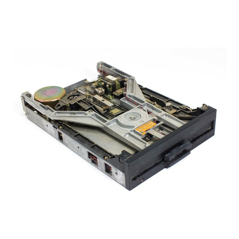
FIGURE
1
-
1
:
MODEL
BASF
6104
DOUBLE
SIDED
FLEXY
DISK
DRIVE

1.
SPECIFICATION
SUMMARY
A
comprehensive
list
of
principal
spe-
cifications
are
provided
in
Table
1-1
The
list
defines
both
single-density
and
double-density
characteristics
,
both
disk
drive
and
interface
levels,
and
all
physid¢al
and
electri-
cal
parameters.
PERFORMANCE
CAPACITY
Unformatted
SPECIFICA
TIONS
Single
Density
Double
Density
per
Disk
800
kilcbytes
1
600
kilobytes
per
Surface
460
kilobytes
800
kilobytes
per
Track
5.2
kilobytes
10.4
kilobytes
IBM
Format
(128
byte
sectors)
per
Disk
500
kilobytes
1000
kilobytes
per
Surface
250
kilobytes
500
kilobytes
per
Track
3.33
kilobytes
6.66
kilobytes
TRANSFER
RATE
250
kilobits/sec.
500
kilobits/sec.
Latency
(Avg.)
83
ms
83
ms
ACCESS
TIME
Track
to
Track
3
ms
3.
ms
Average
(including
settling)
91
ms
91
ms
Settling
Time
14
ms
14
ms
Head
Load
Time
40
ms
40
ms
FUNCTIONAL
SPECIFICATIONS
Rotational
Speed
Recording
Densit
Flux
Density
Track
Density
Cylinder
Tracks
Heads
Sector
index
Enccding
Method
Media
y
(inside
track)
3
Single
Density
360
rpm
+
2,5
%
408 bpi
816 fci
48
tpi
77
154
2
hard
or
soft
1
FM
BASF
Flexy
Disk
2
2
Double
Density
360
rpm
+
2,5
%
816
bpi
815
fci
48
tpi
77
154
2
hard
or
soit
]
MFM
/M
FM
BASF
Flexy
Disk
2)
2
TABLE
1-1
-
SPECIFICATION
SUMMARY

PHYSICAL
Environmental
Limits
SPECIFICATIONS
Ambient
Temperature
10°
C
to
50°
Cc
Relative
Humidity
20
%
to
80
%
Maximum
Wet
Bulb
25°
¢
AC
Power
Requirements
SO
Hz+
2%
Single
Phase
220
VAC
t
10%
0.3
A
(Start-up
0.6
A)
DC
Voltage
Requirements
+24
vpc
=
5%
1.3.
A
typical
+5
vpc
fr
5%
0.8
A
typical
-
5
vpct
5%
0.05
A
typ.
(option
-
7
to
-
16
VDC)
Mounting
Dimensions
*
Width
4
5/8
in.
(110
mn)
Height
10
1/2
in.
(220
mm)
Depth
14
1/4
in.
(360
mm)
Weight
11,0
lbs.
(
5
kg)
Optional
mounting
available
to
allow
installation
of
2
drives
side
by
side
in
RETMA
19
rack.
Heat
Dissipation
300 BTU
/
hr.
typical
RELIABILITY
SPECIFICATIONS
MTBF
6
000
POH
MTTR
30
minutes
Useful
Life
5
years
or
20.
000
hours
Error
Rates
Soft
Read
Errors
1
per
10
9
bits
read
Hard
Read
Errors
1
per
10!
bits
read
Seek
Errors
1
per
10
©
seeks
TABLE
1
-
1
-
SPECIFICATION
SUMMARY
(contd.)

1.5.
1.5.1.
OPTIONS
SUMMARY
There
are
different
options
avail-
able
for
the
BASF
6104.
Most
of
the
options
are
selectable
by
jumpers
on
the
printed
circuit
board
(PCB).
Some
options
must
be
ordered
with
the
drive
or
can
be
installed
by
The
following
tables
different
options.
the
customer.
list
all
the
JUMPER
SELECTABLE
OPTIONS
The
options
of
table
1-2
are
selec-
table
by
setting
of
jumpers
on
the
PCB.
OPT
IONS
FUNCTION
RADIAL
Allows
the
connection
of
4
drives
to
the
host
system.
Each
drive
has
its
own
ad-
dress
(0,
1,
2,
3)
selec-
table
by
a
jumper.
SELECT
SIDE
SELECT
The
head
1
of
the
drive
can
be
selected
in
3
modes
;
-
using
SIDE
SELECT
signal
-
using
STEP
IN
signal
-
using
SELECT
0-3
signals
HEAD LOAD
Loading
of
the
heads
can
be
accomplished
in
three
modes:
-
selected
heads
load
(SELECT
.
HDLOAD)
-
auto
heads
load
(SELECT)
-
radial
heads
load
(HDLOAD)
AUTO
ERASE
The
erase
turn-on
and
erase
turn-off
delays
are
inter-
nally
generated.
WRITE
PROTECT
The
WRITE
PROTECT
signal
is
used
for
designating
of
spe-
cial
diskettes
and
not
for
write
protecting.
TABLE
1
-
2
OPTIONS
FUNCTION
DOOR
LOCK
LATCH
Allows
locking
of
the
door
without
maintaining
the
IN
USE
signal
activated
by
storing
the
state
of
the
IN
USE
signal
into
the
IN
USE
-
flip
flop.
ACTIVITY
INDICATOR
AND
;
DOOR
LOCK
Lighting
of
the
activity
LED
and
locking
of
the
door
can
be
accomplished
as
follows.
:
1.
if
the
heads
are
loaded
-
if
the
drive
is
selected
-
if
the
drive
is
ready
by
the
IN
USE-signal
.
by
the
IN
USE-FF
(DOOR
LOCK
LATCH
OPTION)
6.
if
one
of
1
active
wm
&
Ww
HY
to
3
or
4
is
7.
if
one
of
1
to
3
or
5
is
active
8.
if
one
of
|
to
3
or
4
or
5
is
active
HARD
SECTOR
For
separating
of
INDEX
and
SECTOR
pulses.
Usefull
only
for
hard
sector
diskettes.
-5V
REGULATOR
-5
V
output
voltage
is
gene-
rated
when
an
input
voltage
between
-7
V
and
-16
V
is
applied.
RADIAL
READY
The
READY
signal
is
not
gated
by
SELECT.
RADIAL
INDEX/
SECTOR
The
INDEX
and
SECTOR
signals
are
not
gated
by
SELECT.
RADIAL
STEP
The
STEP
and
the
STEP
IN
signals
are
not
gated
by
SELECT.
OPTIONS
SUMMARY

1.5.2.
FACTORY
INSTALLED
OPTIONS
The
following
options
are
installed
in
the
drive
at
the
factory
or
may
be
installed
by
the
customer.
RECORDING
MEDIA
The
BASF
6104
uses
a
removable
single
sided
or
double
sided
diskette
as
Storage
medium.
Fig.
1-
2
shows
construction
and
dimensions
of
a
typ-
ical
diskette.
The
diskette
is
an
oxide
coated
flex-
OPTIONS
FUNCTION
BINARY SELECT
Up
to
8
drives
may
be
multi-
plexed.
16
OR
8
SECTOR
DIVIDER
Divides
the
32
SECTOR pulses
of
the
hard
sectored
diskette
by
2
or
by
4.
TRUE
OR
FALSE
DATA
SEPARATOR
For
single
density
recording
(FM)
only
!
If
the
true
data
separator
is
selected,
IBM
3470
format
is
accepted.
The
circuit
works
as
a
simple
one
shot
separator
if
the
jumper
is
switched
to
the
false
data
separator.
POSTCOMPEN-
SATION
This
option
allows
reading
and
writing
of
double
density
formatted
diskettes
without
using
of
any
precompensation.
The
drive
is
able
to
read
double
density
diskettes
written
on
IBM
systems.
DOOR
LOCK
SOLENOID
Locks
the
front
door
as
long
as
the
solenoid
is
activated.
TABLE
1-3.
FACTORY
INSTALLED
OPTIONS
ible
disk
enclosed
in
a_
protective
plastic
envelope
with
apertures
for
head
contacts,
index
detection
and
spindle
loading.
The
dimensions
of
single
sided
and
the
double
sided
diskette
differs
only
in
the
location
of
the
index
/
sector
holes.
The
optional
write
protect
hole
is
used
to
protect
the
written
data
on
the
diskette.
SPINDLE
/HUB
SEALED
ACCESS
PROTECTIVE
JACKET
203,2
om
__
a-_—
“
~y
7
N
iN
/
\_
|
LNDEX/SEC
/
O-——_VT
hoe
203,2
\
=
|
,
/
‘
y
Pts
7
>
Le
~~
-
nn
OXIDE
COATED
HEA:
MYLAR
DISK
APERTURE
LINER
WRITE
PROTECT
NOTCH
(OPTIONAL)
TRACK
OO
TRACK
76
INDEX
HOLE
Yo
FIGURE
1
- 2
.
FLEXIBLE
DISK
CONSTRUCTION
AND
DIMENSION

tem
every pulse
represents
a
flux
reversal
on
the
diskette.
4
psec
BITCELL
k—
DATA
pifipirpotrfoyoyotr
tt
DATA
' '
1
’ ' '
a
ior
Sot
Ro
os
ta,
\ 1
2
ps
‘ '
'
‘ ( 1
poima
Rp
ry
tt
'
'
‘
' ' ' ' ' t
WRITE
DATA
WRITE
cpcpcbdDc
cbdC
c
Cc
codec
RECORDING
FORMATS
The
format
of
the
data
_
recorded
on
the
diskette
depends
on
the
host
system.
There
are
two
encoding
schemes
used
for
the
BASF
6104:
e
FM
(Frequency
Modulation)
for
single
density.
e
MFM
_
(Modified
Frequency
Mo-
dulation)
for
double
density.
F
M
-
ENCODING
1.7.2.
This
scheme
utilizes
clocks
to
define
bit
cell
times.
The
presence
of
a
flux
reversal
between
clock
pulses
is
The
of
a
flux
reversal
between
clocks
is
bit.
On
the
write
data
and
read data
interface
defined
as
a
"one"
bit.
absence
"Vero"
defined
as
a
lines
between
disk
drive
and
host
sys-
FIGURE
1
-
3
FM
-
ENCODING
M
F
M
-
ENCODING
A
flux
transition
is
always
recorded
at
the
center
of
the
bitcell
for
each
"one"
data
bit.
No
flux
transitionis
recorded
for
a
"Zero"
bit
unless
it
is
not
followed
by
another
"Zero"bit.
In
this
case
the
flux
transition
is
provided
at
the
end
of
the
first
bit
cell.
2
usec
BITCELL
—
—
[LiTititotitofofofi]
roto
y
fo
Foy
i
1!
t '
—+|3
As
-—!
1
rot
ot
bas
| '
ty
' '
p>
\
DATA
Boe
soe
oe
D
D
OD
D
c
oC
D
FIGURE
1
- 4
.
MFM-
ENCODING
Table of contents
Other BASF Floppy Disk Drive manuals
