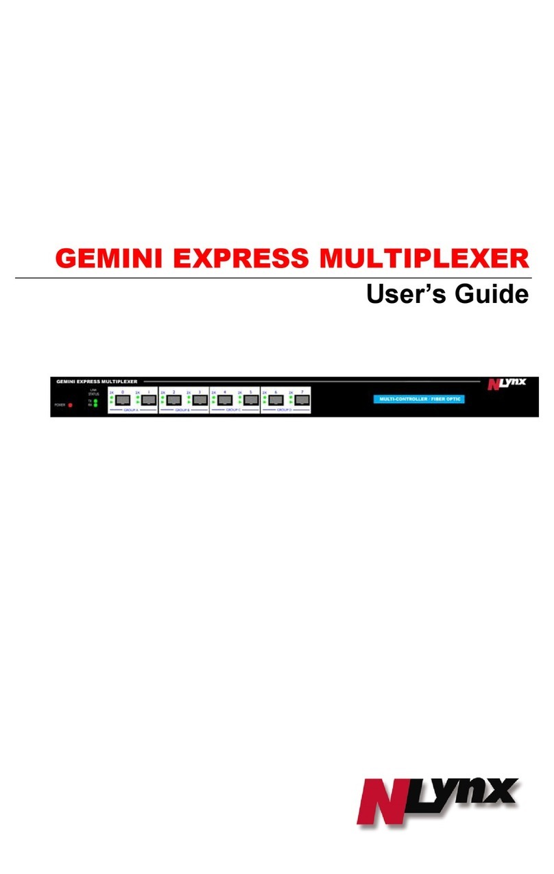
BASF EXACTUS IFM8-IA User manual

EXACTUS
®
IFM8-IA and IFM8-I Industrial Mux User’s Guide
Ver. 1.9
BASF Corporation
Temperature Sensing Group
46820 Fremont Blvd.
Fremont, CA 94538-6540
Phone: (510) 490-2150
Fax: (510) 252-1871
BASF Corporation
Temperature Sensing Group
4011 SE International Way, Suite 604
Portland, OR 97222
Phone: (503) 794-4073
Fax: (503) 794-5591
http://www.catalysts.basf.com/tempsensing
Copyright© 2014 BASF Corporation. All rights reserved.
Exactus and TemperaSure are registered trademarks of BASF Corporation. The data contained in this publication are based on our current
knowledge and experience. In view of the many factors that may affect processing and application of our product, these data do not relieve
processors from carrying out their own investigations and tests; neither do these data imply any guarantee of certain properties, nor the suitability of
the product for a specific purpose. Any descriptions, drawings, photographs, data, proportions, weights, etc. given herein may change without prior
information and do not constitute the agreed contractual quality of the product. It is the responsibility of the recipient of our products to ensure that
any proprietary rights and existing laws and legislation are observed.
Although all statements and information in this publication are believed to be accurate and reliable, they are presented gratis and for guidance only,
and risks and liability for results obtained by use of the products or application of the suggestions described are assumed by the user. NO
WARRANTIES OF ANY KIND, EITHER EXPRESS OR IMPLIED, INCLUDING WARRANTIES OF MERCHANTABILITY OR FITNESS
FOR A PARTICULAR PURPOSE, ARE MADE REGARDING PRODUCTS DESCRIBED OR DESIGNS, DATA OR INFORMATION SET
FORTH. Statements or suggestions concerning possible use of the products are made without representation or warranty that any such use is free of
patent infringement and are not recommendations to infringe any patent. The user should not assume that toxicity data and safety measures are
indicated or that other measures may not be required. ©2014 BASF Corporation.

1
Introduction
The EXACTUS®Industrial Mux (IFM8-IA or IFM8-I) is designed as a data transport device
allowing communication between a host system and up to eight pyrometers. In most situations,
the Industrial Mux can be connected and operate without any setup or configuration changes.
Some of the features that can be configured on Industrial Mux include:
Activation of the analog outputs.
Activation of an instrument monitoring system which detects, and alarms, if any instrument
should fail or otherwise stop communicating.
Configuration of settings which will power down the pyrometer electronics, should their
internal temperature become too high or too low.
Adjustment of pyrometer voltage to compensate for excessive cable resistance.
This guide is divided into sections which provide information on:
1. Product Overview
2. Product Specifications
3. Default Parameters
4. Configuration Communication
5. Configuration Menu
6. Alarm Configuration
7. Analog Output Wiring
8. Mounting
9. Maintenance
10. Warnings
Appendix 1 MODBUS/TCP Implementation
1. Product Overview
The Industrial Mux (IFM8-IA) communicates with up to 8 Exactus® units. It contains four
interfaces for external equipment: current loop (isolated 0-20mA, 16 bit, 8 channels), RS-485
(isolated, 960K), Ethernet (dual 10/100 Mb/s.), and 2 relays (each NO/COM/NC).
Hardware Configuration (see Figure 1-2):
A. Run Status LED (Run)
B. Error Status LED (ERR)
C. Power Status LED (PWR)
D. Reset Button (R)
E. Input 24VDC Power Connection
F. Relay 1 [Form C]
G. Relay 2 [Form C]
H. 2 LAN Ports (LAN1, LAN2) [Ethernet IP and Modbus TCP]
I. 8 Powered RS422 Pyrometer Ports (CH1 to CH8)
J. 1 Isolated RS458 Port (RS485)
K. 1 Auxiliary RS422 Port (AUX)
L. 8 Analog Outputs [Individually Isolated 0-20mA, 16 bit resolution]
Reset Button Function:
1. Depress/Release <3 seconds to reboot Mux with user-selected parameters.
2. Depress/Release >3 seconds to reboot and restore factory default settings. (Including IP
address)

2
Figure 1-1: IFM8-IA Balloon View
Note: Pyrometer channel numbering sequence varies on some hardware configurations.

3
Figure 1-2: IFM8-IA Overview

4
2. Product Specifications
General Specifications
Operating Temperature 0 to 70°C
Storage Temperature -20 to 90°C
Humidity 5 to 95% (non-condensing)
Environmental Air No corrosive gasses permitted
Agency Approvals CE EN61010-1, CB IEC61010-01, EMC
EN61326-1, Pending UL 61010-01 and CSA
C22.2 61010-1
Mechanical/Certifications
Size: H x W x D 63.5mm x 173mm x 90mm, 2.5" x 6.8" x 3.55"
Weight with 4-20mA output option 900g, 32oz
Weight without 4-20mA output option 725g, 26oz
DIN Rail Mount 35mm rail
Input Power
Input Voltage Range +24VDC (+20VDC to +30VDC)
Power Consumption with 8 Pyrometers 14.0 watts, 600mA (+24VDC)
Pin Assignments Pin 1 +V
Pin 2 -V circuit ground
Pin 3 earth/chassis ground
Terminal Type - Removable 3 pin, 5.00/5.08mm plug
NOTE: Relay drive current (17mA for each relay) is not factored into power rating because
relays are only active during an error condition. When active, the system shuts down power to
the pyrometers causing power consumption to drop.
Relays
Number of Outputs 2
Type of Output 2 - Form-C (NO/COM/NC)
Maximum Switching Voltage 300V AC/DC
Contact Current Rating 8A at 24VDC
Maximum Inrush Current 15A (300 ms)
Minimum Load Current 20mA at 24VDC
Rated Carry Current 8A (70°C)/5A (85°C)
Interrupting Rating (ohmic load) max. 190W (24 VDC)
85W (48 VDC)
Fuse No fuse
Commons 2 Isolated
Pin Assignments Pin 1 NO
Pin 2 COM
Pin 3 NC
Terminal Type - Removable 3 pin, 5.00/5.08mm plug

5
TCP/IP Ports
The Industrial Mux has two RJ-45 Ethernet connectors, but only one MAC address and one
TCP/IP address. The ports function as two ports on a switch. Packets entering one connector and
not bound for the IFM8-IA are passed to the other connector, thus the IFM8-IA can be daisy-
chained.
LAN Ports
Communications 10/100 Base T Ethernet
Data Transfer Rate 10/100 Mbps
Link Distance 100 meters
Ethernet Port Connectors RJ45
Port Type Switch
Ethernet Protocols TCP/IP, Modbus TCP/IP, Telnet configuration,
DHCP (Default Protocol IP Address assigned)
Exposed Ethernet Ports
23: Telnet Port for configuration
502: Modbus/TCP Port
6789 : Mux Server Port
6790 : UDP Announcement Port
Pyrometer Ports
Number of input Ports (channels) 8
Connectors RJ-45
Pin Assignments
Pin 1 Tx+ (A) to pyrometer
Pin 2 Tx- (B) to pyrometer
Pin 3 Rx+ (A) from pyrometer
Pin 4 +24VDC (Optional)
Pin 5 Ground
Pin 6 Rx- (B) from pyrometer
Pin 7 Supply +6 to 9.5VDC (configurable),
150mA Max.
Pin 8 Ground
LED Indicators Green: Data from pyrometer
Amber: Data to pyrometer
Electrical Protocol RS-422 Full Duplex
Bit Protocol Asynchronous, 8-bit, 1 stop
Max. Data Rate 921,600 bits/second
Isolation None – pyrometer ground is power
supply/digital ground
Protection ESD protection on all communication lines,
Pyrometer power supply protected against
shorts, +24V not protected

6
Aux Port
Configuration same as Pyrometer Ports Optional
Electrical Protocol RS485 half or full duplex Optional
LED Indicators Green: Data in, Amber: Data out
Analog Output
Number of Outputs 8
Output Range 0-20mA
Resolution 16-bits 0.32uA/bit
Output Type Current modulator
Isolation Individually Isolated Channels
Loop Power External power supply required
Load Impedance (total) 1000ohm max load for 24VDC supply
Output signal at power-up and power down 0mA
Max Update Rate per Channel 4 KHz
Settling Time, Full Scale Change < 5 us
Absolute Accuracy 0.2% of reading, 4-20mA
Accuracy vs. Temperature ±15ppm/°C, 4-20mA
Linearity Error (End to End) ±0.01% of full scale, Monotonic, 4-20mA
Output Stability and Repeatability ±0.4uA after 10min. Warm-up typical
Output Ripple 0.003% of Full Scale
Reverse Polarity Protection Yes, up to 85V
Over-Current Protection Yes, limited to 40mA
Maximum Voltage At Output Pins 48VDC (≤24VDC recommended)
Minimum Voltage At Output Pins 4VDC
Terminal Type - Removable 4 pin, 5.00/5.08mm plug
RS-485 Port
Connector RJ-45
Pin Assignments
Pin 1 D+ (optional Full duplex +TX A)
Pin 2 D- (optional Full duplex -TX B)
Pin 3 (optional Full duplex +RX A)
Pin 4 (optional +24VDC)
Pin 5 (optional Trigger)
Pin 3 (optional Full duplex -RX A)
Pin 7 (optional +6 to 9.5VDC configurable,
150mA Max.)
Pin 8 Ground
LED Indicators Green: Data in
Amber: Data out
Electrical Protocol RS-485 Half Duplex (optional Full duplex)
Bit Protocol Asynchronous, 8-bit, 1 stop
Max. Data Rate 9600 to 921,600 bits/second
Isolation Yes (Internally selectable – port must be non-
isolated to use Pyrometer supply or +24V)
Protection ESD protection on all communication lines,
Pyrometer power supply protected against
shorts, +24V not protected

7
3. Default Parameters
The Exactus® Industrial Mux ships with the following default parameters:
Analog output is enabled. Note: Not all Industrial Mux units will include analog outputs.
(Only Model number IFM8-IA include the analog output ports)
Temperature alarm is set to power down all pyrometers when any pyrometer electronics
temperature drops below 0ºC (32ºF) or goes above 75ºC (167ºF).
The coil for Relay 1 is programmed to energize if the pyrometer temperature limits are
exceeded. Pyrometers will remain powered down until power to the Industrial Mux is cycled
off and back on.
The Pyrometer Supply Voltage is set to 6200mV – adequate for standard pyrometer
power/communication cables up to 15 meters (49 ft).
Note: If these defaults are adequate, no further configuration is necessary.
4. Configuration Communication
If configuration of the Industrial Mux is necessary, a program such as HyperTerminal which is
included with some versions of Microsoft®Windows, can be used. Some versions of the
Exactus® TemperaSure® software include a ‘Configure Mux’ menu in the Advanced Mode of
operation (see figure 4-0).
Figure 4-0: Configure Mux option

8
The following instructions are written for setting up HyperTerminal on Windows XP. Similar
steps can be used for other versions of Windows.
1. Connect a CAT5 cable to either of the ports LAN1 or LAN2 and to an Ethernet input on
the computer. The cable can be of any LAN type.
2. Set the IP address of the PC:
a. Right-click on My Network Places and choose ‘Properties’ from the pop-up menu.
See Figure 4-1.
Figure 4-1: Selecting Properties of My Network Places
b. Double-click on the connection. If there is more than one connection, you can
determine which connection to use by unplugging the LAN cable from the Mux,
and the Status will change to “Network Cable Unplugged”. See Figure 4-2.
Figure 4-2: Network Connections Screen

9
c. The following screen (Figure 4-3) will appear. Click the ‘Properties’ button.
Figure 4-3

10
d. Double-click the “Internet Protocol (TCP/IP)” line (Figure 4-4), this will bring up
the screen shown in Figure 4-5:
Figure 4-4
Figure 4-5

11
e. Click on the radio button ‘Use the following IP address’ and then set the IP address
using the following rules:
i. The first 3 numbers of both the IP address and the Default Gateway must
agree with the first three numbers of the Mux’s address (Default Address =
192.168.1.80).
ii. The last number of the IP address must not be the last number of the
Industrial Mux (e.g. if the Default Address is used, this would be ‘80’).
iii. The last number of the Default Gateway must be 1.
iv. The Subnet Mast must be 255.255.255.0 as shown above.
f. Click OK on all the dialog boxes that are up. Eventually, the Network Connections
dialog (shown in Figure 4-2) will report that the Status is ‘Connected’.
3. Configure the Mux using Windows HyperTerminal
a. Launch Windows HyperTerminal. You should be able to access it using the path
shown in Figure 4-6.
Figure 4-6

12
b. Choose a name (such as IndMux) and an icon as shown in Figure 4-7 and click OK.
Figure 4-7
c. Select the ‘TCP/IP (Winsock)’ option from the “Connect using:” drop-down box,
then enter the Mux’s IP address and click “OK” (See Figure 4-8):
Figure 4-8
d. When you hit the OK buttons, you should get the menu shown in Figure 4-9
Note: Menu structures will very slightly from the illustration dependent on firmware version.

13
Figure 4-9: Configuration Menu
e. After you make changes to the Industrial Mux configuration, be sure the select ‘9.
Save Changes’. As noted, this will reboot the Industrial Mux.
f. HyperTerminal may not automatically display user keystrokes to the screen. To
turn on the echo feature, press the “Properties” button (circled in red in Figure 4-10
below), and select the Settings Tab and press the “ASCII Setup... button” (circled in
blue in Figure 4-10 below) and then select the radio button for “Echo typed
characters locally” (see Figure 4-11):

14
Figure 4-10
Check the “Echo typed characters locally” check box and close the dialog windows.
Figure 4-11

15
5. Configuration Menu
The Configuration Menu is shown in Figure 4-9 above. Below is a description of each menu item:
Network Configuration: Used to set the IP address and other network parameters of the
Industrial Mux. This selection is only used when configuring the Mux for use on your network
rather than connecting directly to a pc.
oIf used on a DHCP enabled network and Option 1 is “No”, the Mux will obtain an
IP address automatically when connected to the network.
Figure 5-1: Network Configuration sub-menu
Pyrometer Supply Voltage (mV): This is the voltage that supplies power to each Exactus®
pyrometer. (Only adjust after consulting with factory and if the pyrometer
communication cable is longer than 15meters; otherwise; it should remain at default
value of 6200mv.)
Mode Options: Used to configure the alarms for individual pyrometers. More detail is
provided in Alarm Configuration section.
Mux Ambient Alarm Configuration: Brings up the Mux Internal Temperature Configuration
Menus; this screen allows a user to define the allowable operating temperatures for industrial
Mux and how the Mux will react to over-temp conditions.
oInternal Temp Upper Limit: Temperature which will trigger error condition.
oInternal Temp Error Closes Relay 1: Will over-temp condition close Relay1?
oInternal Temp Error Closes Relay 2: Will over-temp condition close Relay2?
oRelay polarity: Unlike the other alarms, the polarity of the relay output is
selectable for the Mux over-temp condition. The reason is that if the Mux
overheats, it may become unable to keep a contact closed. By allowing for
selectable polarity, the user can choose to keep the relay in its activated state during

16
normal operation and have an alarm condition open the relay, so if the Mux alarm is
activated the alarm output is active.
Figure 5-2: Mux Internal Temperature Configuration Menu
Restore to Factory Default Values: Restores all settings to the Factory Defaults but you must
follow this with selecting Save Changes.
Save Changes: Saves all settings to their current values and reboots the Industrial Mux. After
saving, a message will be displayed saying ‘rebooting’. You may now end the HyperTerminal
session. If more changes are needed, you will have to click the disconnect icon followed by
the connect icon to reestablish the connection; these icons are located at the top of the
HyperTerminal display.
6. Alarm Configuration
Selecting ’Mode options’ from the Configuration Menu (See Figure 4-9) will bring up the Alarm
configuration menu, shown in Figure 6-1.
Pyrometer Internal Temperature: Selecting Option 3 brings up the Pyrometer Internal
Temperature configuration setup screen shown in Figure 6-2; this screen allows a user to
define the allowable operating temperatures for individual pyrometers. Alarm
temperatures can be configured individually for each pyrometer, as can the action which
will occur should the pyrometer’s temperature goes outside the allowable range. When the
Power Down option is chosen for an instrument, and the condition occurs, all pyrometers
connected to the Industrial Mux will be powered off. The user must cycle the power to the
Mux in order to reset the pyrometers. Depending on the operating speed of the pyrometer,
and other environmental factors, the measured temperature of the electronics can be 5 to
12ºC above the ambient air temperature. The submenu for each pyrometer configuration is
self-explanatory.

17
Figure 6-1: Alarm configuration menu
Figure 6-2: Pyrometer Internal Temperature Alarm Configuration Menu

18
Pyrometer Analog Watchdog: If the Pyrometer Analog Watchdog is activated (Option 4),
the Industrial Mux will watch for missed readings from the pyrometer, an indication that
the pyrometer has failed in some way. If missed readings occur, the analog output will be
forced to the Analog Safe Value and, if programmed to do so, energize one of the relays.
When the Pyrometer Analog Watchdog (Item 4 in Figure 6-1) is enabled, then item “5.
Pyrometer Watchdog Actions” should be configured. This offering has a self-explanatory
submenu for setting the watchdog alarm configuration.
Force Analog Output: Temporarily forces all analog output channels to a user configured
value (0-20mA) for testing purposes.
Analog Safe Value: This is the milliamp output that the analog outputs should go to if
there is a failure with one of the pyrometers

19
7. Analog Output Wiring
The analog outputs for the Exactus® Industrial Mux do not generate a voltage to drive the analog
output and must receive the voltage externally. Many data logging systems are configured to
supply this voltage; if yours is not, you can use the same power supply driving the Industrial Mux
to provide the power. This is outlined in the schematic shown in Figure 7-1:
Figure 7-1: Schematic for providing power to analog output loops – only use if plant data system
does not already provide the loop power.
This manual suits for next models
1
Table of contents
