Viessmann 52292 User manual

Bedienungsanleitung
Operation Manual
AC
~
DC
=
DCC MM
52292
Doppel-Multiplexer
für 2 Lichtsignale mit Multiplex-Technologie
Double-multiplexer
for 2 colour light signals with
multiplex-technology
1. Wichtige Hinweise / Important information ........................................................ 2
2. Einleitung / Introduction..................................................................................... 3
3. Anschluss / Connection..................................................................................... 5
4. Konguration / Conguration............................................................................. 10
5. Betrieb / Operation ............................................................................................ 10
6. Signal-Logik / Signalling logic............................................................................ 15
7. Verwendbare Signale / Suitable signals ............................................................ 20
8. DIP-Schalter Funktionen / DIP-switch functions................................................ 22
9. Gewährleistung / Warranty................................................................................ 23
10.Technische Daten / Technical data................................................................... 23

2
DE EN
1. Wichtige Hinweise
Bitte lesen Sie vor der ersten Anwendung des Produktes
bzw. dessen Einbau diese Bedienungsanleitung aufmerk-
sam durch. Bewahren Sie diese auf, sie ist Teil des Pro-
duktes.
1.1 Sicherheitshinweise
Vorsicht:
Stromschlaggefahr!
Die Anschlussdrähte niemals in eine Steckdose ein-
führen! Verwendetes Versorgungsgerät (Transfor-
mator, Netzteil) regelmäßig auf Schäden überprüfen.
Bei Schäden am Versorgungsgerät dieses keinesfalls
benutzen!
Alle Anschluss- und Montagearbeiten nur bei abge-
schalteter Betriebsspannung durchführen!
Ausschließlich nach VDE/EN-gefertigte Modellbahn-
transformatoren verwenden!
Stromquellen unbedingt so absichern, dass es bei
einem Kurzschluss nicht zum Kabelbrand kommen
kann.
Für die Montage sind Werkzeuge nötig.
1.2 Das Produkt richtig verwenden
Dieses Produkt ist bestimmt:
- Zum Einbau in Modelleisenbahnanlagen und
Dioramen.
- Zum Anschluss an einen Modellbahntransformator (z. B.
Art.-Nr. 5200, 5201) bzw. an einer Modellbahnsteuerung
mit zugelassener Betriebsspannung.
- Zum Betrieb in trockenen Räumen.
- Zur Ansteuerung von Licht-Signalen mit Multiplex-
Technologie.
Jeder darüber hinausgehende Gebrauch gilt als nicht
bestimmungsgemäß. Für daraus resultierende Schäden
haftet der Hersteller nicht.
1.3 Packungsinhalt überprüfen
Kontrollieren Sie den Lieferumfang auf Vollständigkeit:
- Doppel-Multiplexer für 2 Lichtsignale mit
Multiplex-Technologie
- 2 Schrauben
- Anleitung
1. Important information
Please read this manual completely and attentively be-
fore using the product for the rst time. Keep this manual.
It is part of the product.
1.1 Safety instructions
Caution:
Electrical hazard!
Never put the connecting wires into a power socket!
Regularly examine the transformer for damage. In
case of any damage, do not use the transformer!
Make sure that the power supply unit (transformer,
power supply) is switched off when you mount the de-
vice and connect the cables!
Only use VDE/EN tested special model train trans-
formers for the power supply!
The power sources must be protected to
avoid the risk of burning cables.
Tools are required for intallation.
1.2 Using the product for its correct pur-
pose
This product is intended:
- For installation in model train layouts and dioramas.
- For connection to an authorized model train trans-
former (e. g. item-No. 5200, 5201) or a digital com-
mand station.
- For operation in dry rooms only.
- For connection to a colour light signal with
multiplex-technology.
Using the product for any other purpose is not approved
and is considered inappropriate. The manufacturer is not
responsible for any damage resulting from the improper
use of this product.
1.3 Checking the package contents
Check the contents of the package for completeness:
- Double-multiplexer for 2 colour light signals with
multiplex-technology
- 2 Screws
- Manual

3
2. Einleitung
Beim Doppel-Multiplexer (Art.-Nr. 52292) handelt es
sich um ein Steuermodul mit integriertem Digitaldecoder
(MM, DCC) für 2 Viessmann Hauptsignale mit Multiplex-
Technologie, z. B. Ks-Signale (Art.-Nr. 4042 – 4046) und
Standard-Lichtsignale (Art.-Nr. 4721 – 4728). Das Modul
steuert 2 unabhängige Hauptsignale und erkennt die an-
geschlossenen Signale automatisch. Bilden Haupt- und
Vorsignal eine Einheit (Hp/Vr-Kombinationen), können
diese auch mit eigenen Adressen unabhängig voneinan-
der gesteuert werden.
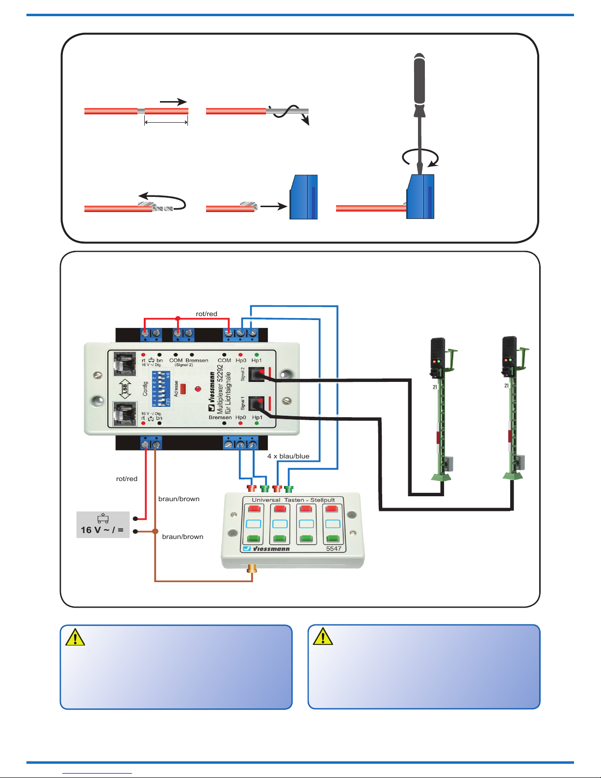
Dieses Modul ist die ideale Steuerung für die Viessmann
Signalbrücken (Art.-Nr. 4750 und 4755). Es steuert alle
montierten Signale (Art.-Nr. 4751 – 4753) zuverlässig und
verfügt über analoge Eingänge für das Tastenstellpult
(Art.-Nr. 5547).
Die Signale können auch über Gleiskontakte und durch
digitale Schaltbefehle über das Gleis geschaltet werden.
Der SpeedBus (LSB) ermöglicht den komfortablen An-
schluss und Betrieb am Viessmann Commander (Art.-Nr.
5300) mit automatischer Anmeldung inklusive Darstellung
im Gleisplan.
Das Modul hat keinen realen Signalbus wie (Art.-Nr.
5229) Multiplexer für Lichtsignale mit Multiplex-Techno-
logie. Es besitzt dafür einen virtuellen Signalbus, siehe Ka-
pitel 5.8. Der Signalanschluss erfolgt über eine einzige
Steckverbindung. Ein weicher Lichtwechsel zwischen den
Signalbildern sowie weitere Eigenschaften sind einstell-
bar. Signalbilder und Adressen nden Sie auf den Seiten
20 und 21.
Der Doppel-Multiplexer erkennt automatisch den an-
geschlossenen Signaltyp und konguriert sich entspre-
chend. In Verbindung mit dem Viessmann Commander
(Anschluss am LSB) kann sich das Modul automatisch
digital kongurieren.
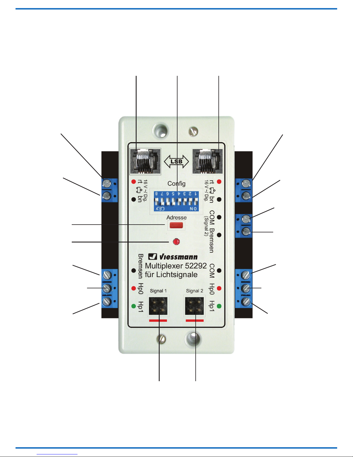
Bei Verwendung anderer Digitalzentralen bzw. im analo-
gen Betrieb werden Optionen über DIP-Schalter (siehe
Abb. 5) und gegebenenfalls auch Digitaladressen manu-
ell eingerichtet. Bei diesem Vorgang werden gleichzeitig
die Eigenschaften des zu steuernden Signals konguriert:
- Sofortiges oder weiches Überblenden der
Signalbilder.
- Gekoppeltes Signal (nur Hp0 und Hp2).
- Bahnhofs- oder Blockstrecken-Logik.
- Bremsmodul ja/nein.
Die einmal eingestellte Konguration und das aktuelle
Signalbild werden intern gespeichert und bei jedem Spiel-
beginn wieder zurückgeholt.
2. Introduction
The double-multiplexer (item-No. 52292) is a
control module with integrated digital decoder (MM, DCC)
for 2 Viessmann home signals suitable for multiplex-
technology, e. g. Ks-signals (item-No. 4042 – 4046) and
standard colour light signals (item-No. 4721 – 4728). The
module controls to 2 independent home signals and de-
tects the connected signals automatically. If a home sig-
nal and a distant signal are combined on one mast they
can still be controlled separately by assigning different
addresses to them.
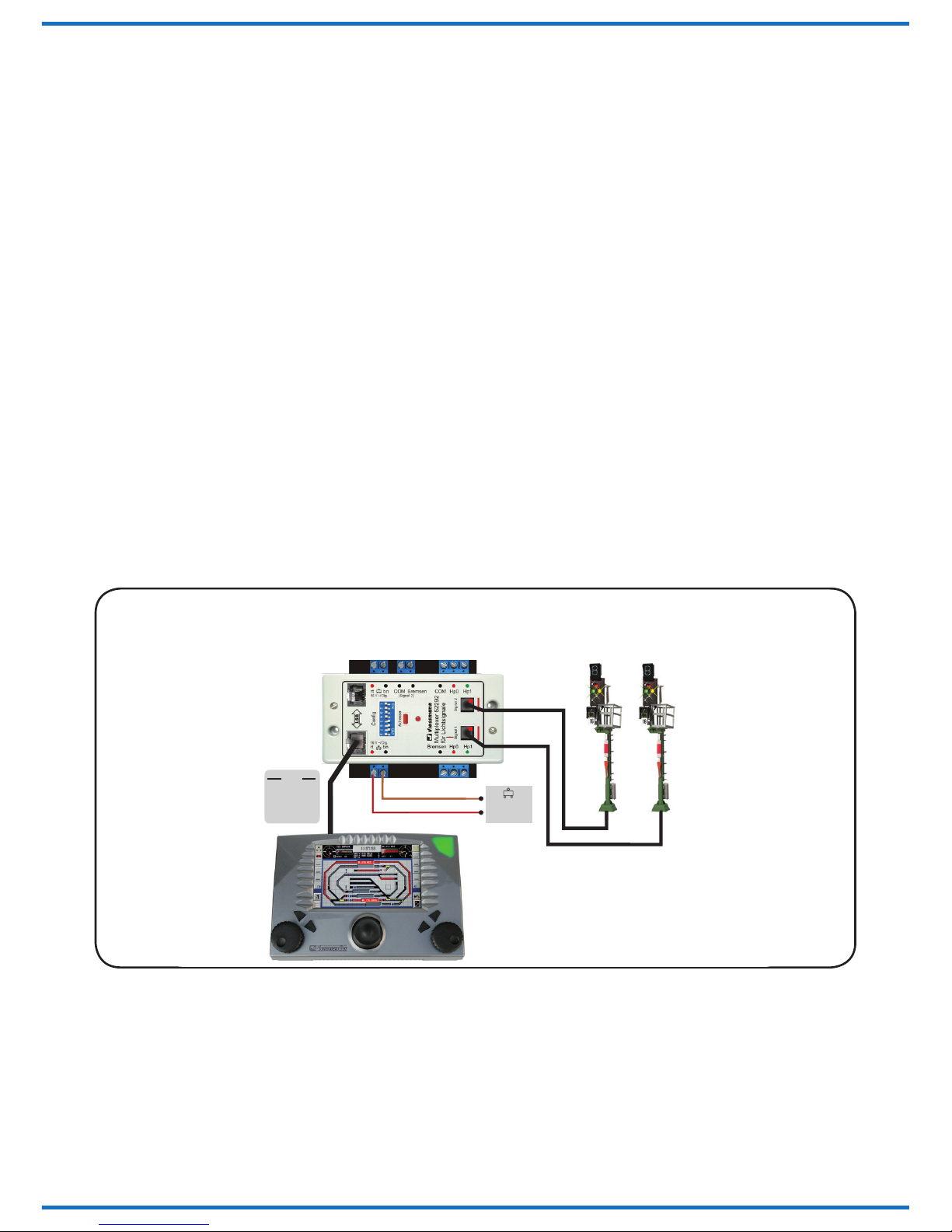
This module is the ideal option for controlling the Viess-
mann signal bridges (item-No. 4750 and 4755). It reliably
controls all signal types (item-No. 4751 – 4753) installed
on the signal bridge and also has analogue inputs for
a push button panel such as the Viessmann (item-No.
5547).
The signal can also be digitally controlled via track con-
tacts. The Speed-Bus (LSB) facilitates the comfortable
electrical connection and operation with automatic detec-
tion and recognition of the signal by the Viessmann Com-
mander (item-No. 5300) including the images symbol in
the track diagramm.
This module cannot be connected via real signal bus like
(item-No. 5229) multiplexer for colour light signals with
multiplex-technology. Instead of this it has a virtual signal
bus, see chapter 5.8.
The signals are connected by simply inserting the plug
into the appropriate socket of the module.
A soft change between signal aspects as well as other
parameters can be adjusted.You will nd possible signal
aspects and addresses on pages 20 and 21.
The double-multiplexer auto-detects the type of signal
connected and congures itself accordingly. When con-
nected to the Viessmann Commander via the LSB the
double-multiplexer will congure itself automatically (pro-
gramming the digital address).
Using other digital command stations or when operating
in analogue mode various options can be switched on or
off by setting DIP-switches (see g. 5). If applicable digi-
tal addresses may also be assigned manually. During this
process the parameters of the signal to be controlled will
be congured simultaneously:
- Immediate or soft change of signal aspects.
- Coupled signal (only Hp0 and Hp2) with 2 aspects
only
- Yard- or block signalling logic.
- Brake module yes/no.
The set conguration and the signal aspects will be
saved in the module and will be restored whenever the
control system is switched on again.

4
Anschluss rt:
rot = Phase
Connection rt:
red = phase
Anschluss bn:
braun = Masse
Connection bn:
brown = ground
LSB Anschluss
LSB connection
LSB Anschluss
LSB connection
DIP-Schalter
DIP-switches
Taste Adresse
Button address
Steckplatzanschluss Signal 1
Plug-in connection for signal 1
Steckplatzanschluss Signal 2
Plug-in connection for signal 2
Status-LED
Status-LED
Anschluss rt:
rot = Phase
Connection rt:
red = phase
Anschluss bn:
braun = Masse
Connection bn:
brown = ground
Gemeinsamer
Rückleiter für
Steuerleitung
Common return
for control cable
Eingang Bremsen
Input brake
Eingang Bremsen
Input brake
Eingang Signalbild Hp0
Input signal aspect Hp0
Eingang Signalbild Hp1
Input signal aspect Hp1
Eingang Signalbild Hp0
Input signal aspect Hp0
Eingang Signalbild Hp1
Input signal aspect Hp1
Gemeinsamer
Rückleiter für
Steuerleitung
Common return
for control cable
2.1 Anschlussbelegung 2.1 Connection assignment

5
2.2 Vorsignal
Hinweis
Einzeln stehende separate Vorsignale können am
Doppel-Multiplexer nicht angeschlossen werden.
Verfügen die am Doppel-Multiplexer angeschlossenen
Hauptsignale über ein Vorsignal am gleichen Mast, dann
gehört dieses Vorsignal „am Mast“ funktional zum fol-
genden Hauptsignal und kann auch darüber angesteuert
werden. Es erhält somit die erforderlichen Informationen
über die Digitaladresse des folgenden Hauptsignals und
zeigt das entsprechende Signalbild an.
Der Vorsignalbegriff wird über die jeweilige Digitaladres-
se des folgenden Hauptsignals erfasst. In den Stellungen
„Halt“, „Rangierbetrieb“ oder „Nur Rangierbetrieb erlaubt“
wird das Vorsignal am eigenen Mast automatisch dunkel
geschaltet. Diese „Dunkeltastung“ entspricht dem Vorbild,
denn wer nicht weiterfahren darf, braucht die Stellung
des nächsten Hauptsignals nicht zu kennen.
2.3 Update
Der Doppel-Multiplexer ist aktualisierbar. Mit dem
Viessmann Commander und einem Windows PC können
Sie jederzeit selbst eine neue Software-Version über den
LSB auf den Doppel-Multiplexer aufspielen. Die Beschrei-
bung nden Sie im jeweiligen Update-Paket für den Com-
mander und die einzelnen Schritte im entsprechenden
Menü auf dem Commander sowie in den Informationen
zum Update auf unserer Homepage.
3. Anschluss
Schließen Sie den Doppel-Multiplexer (siehe Abb. 2
(analog) bzw. Abb. 3 (digital)) an eine Stromversorgung
an. Stecken Sie den Signalstecker in die entsprechende
Buchse des Doppel-Multiplexers. Achten Sie auf die kor-
rekte Polarität. Die Markierung am Stecker muss mit
der Markierung am Doppel-Multiplexer übereinstimmen.
Sollte der Stecker umgedreht eingesteckt werden (ver-
tauschte Polung) entstehen keine Schäden. Allerdings
wird das Signal dann nicht richtig erkannt und deshalb
inkorrekt angesteuert. Nach erfolgtem Anschluss des
Signals an die Signalbuchse halten Sie die rote Taste
„Adresse“ solange gedrückt, bis Sie die Stromversorgung
eingeschaltet haben. Der Multiplexer liest nun das an-
geschlossene Signal ein. Nach erfolgreicher Identizie-
rung speichert er den dazugehörigen Signaltyp ab. Zum
Anschluss des Doppel-Multiplexers an die Steuerung Ih-
rer Modellbahn (Stellpulte, Digitalzentrale) beachten Sie
bitte die nachfolgenden Kapitel 3.1 – 3.4 sowie die Abbil-
dungen 1 – 4.
2.2 Distant signal
Note:
Individually installed distant signals cannot be con-
nected to the double-multiplexer.
If the signals connected to the double-multiplexer consist
of a home signal as well as a distant signal mounted to
the same mast, then the distant signal is logically linked
to the following home signal. Therefore it also can be
controlled like the following home signal by assigning the
same address to both signals.
Thus the distant signal will always show the correspon-
dig aspect to the following home signal. In case of a
signal aspect showing “stop” or “shunting movement” or
”only shunting movement” allowed” the distant signal at
the own mast will be masked automatically. A “masked”
signal complies the principle of the real railway. If you
cannot proceed on your journey route, the aspect of the
proximate signal must not be known.
2.3 Update
The double-multiplexer is updatable. With the
Viessmann Commander and a Windows PC you can in-
stall the latest software version onto the double-multiplex-
er via the LSB. You will nd the description in the relevant
update package for the Commander and the individual
steps in the menu of the Commander. For more informa-
tion please visit our homepage.
3. Connection
Connect the double-multiplexer (see g. 2 (analogue) or
g. 3 (digital)) to a power supply. Insert the plug of the
signal into the appropriate socket of the double-multiplex-
er. Please observe the correct polarity. The mark on the
plug must be aligned with the mark on the double-multi-
plexer. Inserting the plug the wrong way around (wrong
polarity) will not result in any damage. However, the sig-
nal cannot be detected correctly and control of the signal
will be unpredictable. After successful connection of the
signal to the signal socket press the red button “Adresse”
as long as you have turned on the power supply. The
multiplexer starts the installation of the signal automati-
cally. If the signal has been identied correctly the cor-
responding signaltype will be stored. Please observe the
following chapters 3.1 – 3.4 and g. 1 – 4 regarding the
connection of the double-multiplexer to your control sys-
tem (push button panels, digital command station).

6
1. 2.
3. 4. 5.
Litzen einschiebenLitzen umbiegen
Litzen verdrillenKabel abisolieren
Schraube festziehen
Insert litz wiresBend litz wires
Twist litz wiresCable insulation
Tighten screw
5 mm
Fig. 1
Abb. 1 Kabel befestigen
Fasten the cable
Nur für Litzen bis
0,14 mm³!
Only for litz wires
up to 0,14 mm³!
Analoger Anschluss Analogue connectionAbb. 2 Fig. 2
braun/brown
4 x blau/blue
rot/red
rot/red
braun/brown
16 V ~ / =
52292 z. B./e. g. 4721
5547
Hinweis
Bei Ersteinrichtung oder Änderung des Signals drü-
cken Sie die rote Taste „Adresse“ und halten Sie die-
se gedrückt. Schalten Sie dann die Stromversorgung
ein. Das Signal wird automatisch identiziert und der
Signaltyp anschließend dauerhaft abgespeichert.
Note
During the rst installation or changing the signal,
press the red button “Adresse” and hold it. Then turn
on the power supply. The identication of the signal
will start automatically. Afterwards the signaltype will
be stored permanently.

7
3.1 Konventioneller (analoger) Betrieb
Im Analogbetrieb bietet der Doppel-Multiplexer eine ein-
geschränkte Funktionalität. Beide Signale haben je 2
Begriffe, die über die analogen Eingänge steuerbar sind:
Hp0 (rot) und Hp1 (grün). Mehrbegrifge Signale, die auf
gekoppelt konguriert sind (DIP-Schalter 2 und 3 on),
schalten zwischen Hp0 (rot 0 = stop), und Hp2 (grün und
gelb = Langsamfahrt).
Den ersten und zweiten Begriff schalten Sie im analogbe-
trieb z. B. mit Hilfe des Viessmann Tastenstellpults (Art.-
Nr. 5547 (für vier 2-begrifge Signale)). So entsprechen
Farbe und Anordnung der Tasten dem jeweiligen Signal-
bild und dessen Stellmöglichkeiten (rot und grün). Analog
lassen sich über ein Stellpult am 52292 maximal 2 Be-
griffe schalten, was die Multiplex-Hauptsignale und die
Lichtsperrsignale betrifft.
Eine Steuerung der dritten und vierten Begriffe ist im ana-
logen Betrieb mit dem 52292 nicht möglich (Ausnahme
DIP-Schalter 2 und 3 sind on, d. h. das Signal ist auf ge-
koppelt konguriert).
Moderne Ks-Signale haben teilweise 4 oder mehr Signal-
begriffe und sollten sinnvollerweise digital angesteuert
werden.
Die beiden COM Anschlüsse des Doppel-Multiplexers
sind intern miteinander verbunden. Sie müssen mit dem
Anschluss „rt“ verbunden werden.
Hinweis für Gleichstrombetrieb:
Beachten Sie beim Betrieb mit Gleichstrom
unbedingt die Polarität:
Rot = Plus
Braun = Minus
3.2 Diorama-Modus
Zur Belebung von Dioramen oder Schaustücken kann es
gewünscht sein, die Signalstellung in einer willkürlich ab-
laufenden Sequenz zu verändern. Um diesen Modus zu
aktivieren, verbinden Sie einfach die 4 Analoganschlüsse
(Hp0 und Hp1) miteinander und mit dem braunen Kabel
vom Trafo (siehe Abb. 3a) und schalten anschließend die
Stromversorgung ein.
Dieser Modus bleibt solange aktiv bis die Stromversor-
gung wieder ausgeschaltet wird.
3.3 Digitaler Anschluss (am Gleis)
Beim Digitalbetrieb verbinden Sie die Klemmen „rt“ und
„bn“ mit dem Gleisausgang einer Digitalzentrale oder
eines Boosters (siehe Abb. 3).
Parallel zu einer Digitalzentrale können Sie ein externes
Tastenstellpult an den Doppel-Multiplexer anschließen
und so auch von Hand, 2 Signalbegriffe steuern. Aller-
dings wird in diesem Fall die Stellinformation nicht an die
Digitalzentrale gemeldet.
3.1 Conventional (analogue) operation
In analogue mode the double-multiplexer only offers lim-
ited functionality. Both signals only have 2 aspects that
can be controlled via the analogue inputs: Hp0 (red) and
Hp1 (green). Multi-aspect signals congured as locked
signals (DIP-switches 2 and 3 on) can switch between
Hp0 (red = stop) or Hp2 (green and yellow = proceed at
limited speed).
You can activate the rst and second signal aspect in
analogue mode e. g. with the aid of Viessmann push
button panel (item-No. 5547) (for four 2-aspect signals).
Thus colour and arrangement of the push buttons cor-
respond with the signal aspects (red and green). In ana-
logue mode you can only switch 2 signal aspects with the
52292. This concerns the multiplex home signals and the
colour light block signals.
Activating the third and fourth signal aspect cannot be
accomplished with the 52292 (one exception: If the DIP-
switches 2 and 3 are switched on and therefore the sig-
nal) is congured for a coupled type 2-aspect signal.
Some modern Ks-signals may have 4 or more signal as-
pects and should therefore be controlled in digital mode.
The COM ports of the double-multiplexer are linked to-
gether. They have to be connected with the “rt” pin.
Note for DC current operation:
Please observe absolutely the polarity, when operat-
ing with DC current:
red = plus
brown = minus
3.2 Diorama mode
In order to enliven dioramas or displays it may be desir-
able to change the signal aspects in an automated but
arbitrary sequence. In order to activate this mode simply
connect all 4 analogue inputs (Hp0 and Hp1) with each
other and with the brown wire from the transformer (see
g. 3a) and then turn on the power supply.
This mode remains active until the power supply is turned
off again.
3.3 Digital connection (directly to the
track)
For digital operation please connect the terminals “rt” and
“bn” with the track outputs of your command station or a
booster (see g. 3).
In addition you may also connect a push button panel to
your double-multiplexer for manual control 2 signal as-
pects. However, the manually activated signal aspect will
not be reported to the command station.

8
Abb. 3a Anschlussschema für Diorama-Modus
Connection diagram for diorama-modus
braun/brown
rot/red
rot/red
braun/brown
16 V ~ / =
52292
Fig. 3a
Digitaler Anschluss am Gleis
Digital connection (directly to the track)
Fig. 3
Abb. 3
Mot./DCC
Digitalzentrale/Booster
rot/red braun/brown
Digital command station/Booster
52292
z. B./e. g. 4046

9
3.4 Digitaler Anschluss am LSB
Sofern Sie den Viessmann Commander als Digitalzen-
trale verwenden, sollten Sie den Doppel-Multiplexer über
den leistungsfähigen SpeedBus LSB anschließen (siehe
Abb. 4). Nutzen Sie zur Verbindung von LSB-Geräten bit-
te unsere speziellen LSB-Kabel (Art.-Nr. 5390 – 5393).
Diese sind mit Steckern konfektioniert und sofort einsetz-
bar. Die beiden LSB-Buchsen des Doppel-Multiplexers
sind parallel geschaltet. Verbinden Sie eine der beiden
Buchsen per LSB-Kabel mit dem Commander.
An die andere Buchse können Sie weitere LSB-Geräte
anschließen. Die Verbindung zum Commander kann
auch indirekt über weitere LSB-Geräte erfolgen. Der Dop-
pel-Multiplexer meldet sich dann automatisch am Com-
mander an und konguriert sich selbst (Autokongura-
tion).
Die 2 Stelleingänge des Doppel-Multiplexers Hp0 und
Hp1 lassen sich optional auch als Rückmeldekontakte für
den Betrieb einer Blockstrecke verwenden (siehe Abb. 6).
Die Eingänge „Bremsen“ können für das zielgenaue
Schalten eines Bremsmoduls, (z. B. Art.-Nr. 5232 (Mär-
klin-Motorola)) oder eines Bremsgenerators (DCC) für
das jeweilige Hauptsignal verwendet werden. Beach-
ten Sie bitte die Hinweise im Abschnitt 6.3 und 6.4. Die
Bremsmodule bzw. die Bremsgeneratoren werden jeweils
über ein monostabiles Relais (z. B. Art.-Nr. 5227) am je-
weiligen Schaltausgang des Art.-Nr. 52292 angeschlos-
sen.
3.4 Digital connection via LSB
If you use the Viessmann Commander as digital com-
mand station, we recommend connecting the double-mul-
tiplexer via the powerful SpeedBus LSB (see g. 4). For
connection we recommend our special LSB cables (item-
No. 5390 – 5393). They are ready-made complete with
plugs. The LSB sockets of the double-multiplexer are par-
allel connected. Therefore you can plug in the LSB cable
into either LSB socket. Use the other one for extending
the connection to other LSB devices.
It is immaterial if you connect the double-multiplexer di-
rectly to the LSB socket of the Viessmann Commander or
to any other LSB device that is already connected to the
Viessmann Commander. As mentioned before, the
double-multiplexer will be automatically detected by the
Viessmann Commander and auto-congures itself.
The 2 inputs Hp0 and Hp1 of the double-multiplexer may
also be used as feedback inputs for operating block sec-
tors (see g. 6).
The inputs “Bremsen” (“braking”) may be utilized for pre-
cise switching of a brake module (e. g. item-No. 5232
(Märklin-Motorola)) or a brake generator (DCC) for the
respective home signal. Please observe the remarks in
the chapter 6.3 and 6.4. The brake modules respectively
the brake generators will be connected via a monostable
relay (e. g. item-No. 5227) to the corresponding output of
the item-No. 52292.
Abb. 4 Digitaler Anschluss am LSB
Digital connection via LSB
braun/brown
LSB
5390 –
5391 –
5392 –
5393 –
16 V ~ / =
LSB
28 cm
60 cm
215 cm
600 cm z. B./e. g. 5200
rot/red
Fig. 4
52292
5300
z. B./e. g. 4046

10
4. Konguration
Nach Anschluss des Doppel-Multiplexers an eine Strom-
versogung muss dieser konguriert werden. Nur bei An-
schluss über den LSB an den Commander kann die Kon-
guration automatisch erfolgen.
Informationen zum Anschluss des Doppel-Multiplexers
an den Viessmann Commander nden Sie im Referenz-
handbuch zum Commander (Art.-Nr. 53002).
4.1 Optionen
Die möglichen Signaloptionen werden über die DIP-
Schalter („Mäuseklavier“) des Doppel-Multiplexers einge-
stellt (siehe Tabelle auf Seite 22). Die Stellungen der DIP-
Schalter werden nur nach Aus- und Wiedereinschalten
des Moduls eingelesen und übernommen.
5. Betrieb
5.1 Allgemeines
Das Modul benötigt zur Ansteuerung im Märklin-
Motorola- und im NMRA-DCC-Betrieb pro Signal bis
zu 4 direkt aufeinander folgende Digitaladressen. Bei
einem mehrbegrifgen Signal, das mehr als eine Adresse
benötigt, ist die erste Adresse immer eine ungerade Zahl.
5.2 Anschluss externer Kontakte
Es können bis zu 3 externe Kontakte oder Taster pro
Signal angeschlossen werden, über die das Signalmo-
dul z. B. auch vom Zug aus geschaltet werden kann.
Zwei für die Stellungen „rot“ und „grün“, der dritte An-
schluss („Bremsen“) ist für den Bremskontakt, der beim
Anschluss eines Bremsmoduls bzw. Bremsgenerators
die Umschaltung des Fahrstroms von „Fahren“ (Zentra-
le/Booster) auf „Bremsen“ (Bremsmodul/Bremsgenera-
tor) auslöst. Ohne Bremsmodul/Bremsgenerator wird die
Fahrstromunterbrechung sofort wirksam, wenn das Si-
gnal auf „Halt“ gestellt wird. Die Ein-/Ausschaltung bzw.
die Umschaltung des Fahrstroms übernimmt ein mono-
4. Conguration
The double-multiplexer must be congured after connect-
ing it to a power supply. An automatic conguration of the
double-multiplexer is executed, when connected to the
Commander by the LSB only.
You will nd information about the connection of the
double-multiplexer to the Viessmann Commander in the
reference manual of the Commander (Item-No 53003).
4.1 Options
All possible signal options are set with the DIP-switches
on the double-multiplexer (refer to the table on page 22).
The settings of the DIP-switches will be read out and
stored only after the power is turned off and on.
5. Operation
5.1 General information
The module may require up to 4 consecutive digital
addresses for each signal in either digital mode
(Märkling-Motorola/DCC). The rst address of a multi-
aspect signal requiring more than one address is always
an uneven number.
5.2 Connection of external contactors
You may connect up to 3 external contacts or push but-
tons for each signal connected to the item-No. 52292.
This allows manual switching or activation also e. g. by
the trains. There are 2 inputs for the “stop” and “proceed”
aspects, the third one is for “braking”. The braking input
is used for triggering the change over from normal “driv-
ing” (powered by the command station or the booster) to
“braking” (powered by the brake module / brake genera-
tor). Without a braking device the track current will be
interrupted immediately once the signal is set to “stop”.
The track current is switched by a monostable relay to be
plugged directly onto the side of the double-multiplexer
ON
12345678
WnP
DIP-Schalter
Ein
Aus
DIP-switches
/ On
/ Off
Fig. 5
Abb. 5

11
stabiles Relais, das direkt am seitlichen Ausgang des
52292 angesteckt wird (z. B. Art.-Nr. 5227) (siehe Abbil-
dung 7).
Das Relais (Art.-Nr. 5227) besitzt je 2 Umschaltkontakte
für jedes der beiden separaten Relais dieser Einheit. Ein
Relais wird für die signalabhängige Schaltung des Fahr-
stroms wie oben beschrieben verwendet, das zweite
kann für das zweite Signal am Doppel-Multiplexer einge-
setzt werden.
Mit den Umschaltkontakten kann jede Stromform, d. h.
Gleichstrom, Wechselstrom und auch Digitalstrom, ge-
schaltet werden. Die maximale Strombelastbarkeit der
Kontakte beträgt 2 A.
5.3 Programmierung
Der Doppel-Multiplexer muss am Gleisausgang einer
Zentrale angeschlossen sein.
Während der Programmierung darf kein LSB-Kabel
angeschlossen sein!
Ein Drücken der roten Taste „Adresse“ für ca. 2 Sekun-
den stellt das Modul auf Empfang im Programmiermodus
und scannt gleichzeitig die angeschlossenen Signale.
Beachten Sie, dass je nach Signaltyp eine unter-schied-
liche Anzahl von Digitaladressen benötigt wird. Eine
Faustregel besagt, dass jedes Signal halb so viele Adres-
sen (aufgerundet) benötigt, wie es Begriffe anzeigen
kann.
Die erste gesendete Digitaladresse einer Zentrale wird
immer als Basisadresse gespeichert, die restlichen be-
nötigten Adressen (kann je nach automatisch erkanntem
Signaltyp unterschiedlich sein) werden automatisch im
Doppel-Multiplexer gespeichert. Wie schon erwähnt, rich-
tet sich die Anzahl nach der Art des angeschlossenen Si-
gnals. Man sollte im Digitalsystem Platz für die zusätz-
lichen Adressen frei lassen, wenn man die Adressen ma-
nuell einstellen möchte (DIP-Schalter 6 off). Die automa-
tische Programmierung (DIP-Schalter 6 on) sorgt selbst
dafür, dass entsprechende Lücken zwischen den Adres-
sen zum nächsten Signal eingehalten werden.
Bitte beachten Sie dabei:
- Blocksignale und Sperrsignale haben 2 Begriffe,
brauchen dafür also nur eine Digitaladresse.
- Doppelte Adressvergabe ist zu vermeiden, da sie zur
Beeinussung der jeweiligen doppelt addressierten
Signale führt.
- Ausnahmen siehe Kapitel 5.7 auf Seite 13.
- Einfahr-, Ausfahr- und Ks-Signale können 3 oder 4
Begriffe anzeigen, deshalb brauchen diese 2 aufei-
nander folgende Digitaladressen.
- Das Ks-Mehrabschnittssignal (Art.-Nr. 4045) benötigt
4 aufeinander folgende Adressen.
(e. g. item-No. 5227) (see g. 7).
The relay (item-No. 5227) consists of 2 relays with 2
sets of change over contacts each. One relay is used for
switching the track current subject to the signal aspect.
The second relay may be used in the same manner for
the second signal connected to the double-multiplexer.
The relay contacts can handle any type of current, that is
DC, AC or digital current. The maximum current is 2 A.
5.3 Programming
The Viessmann double-multiplexer must be connected to
the track output of a digital command station.
During programming the LSB must be disconnected!
Pressing the red button “Adresse” for about 2 seconds
sets the module into reception mode (programming) while
it scans the connected signals.
Please note that the number of required addresses de-
pends on the type of signals connected to the module. As
a rule of thumb each signal needs about half as many ad-
dresses as its number of possible signal aspects.
The rst address transmitted by the command station is
stored as the basis address. The remaining required ad-
dresses will be stored automatically in the double-multi-
plexer. As already mentioned, the number of addresses
depends on the type of signal. It is advisable to leave
sufcient address numbers open when programming
addresses manually (DIP-switch 6 off). In automatic pro-
gramming mode (DIP-switch 6 on) the module automati-
cally reserves the right number of addresses before pro-
gramming the basis address of the next signal.
Please note:
- Block signals and colour light stop signals only have 2 as-
pects and therefore only one address is required.
- In order to avoid unintentional incorrect signalling
avoid assigning the same address to different signals.
- Also note the exceptions listed in the chapter 5.7 on
page 13.
- Home-, exit- and Ks-signals can show 3 or 4 aspects.
Therefore they require 2 consecutive addresses.
- The Ks-multi sector signal as entry signal (item-No.
4045) requires 4 consecutive addresses.

12
5.4 Digitaladresse (Märklin-Motorola)
Das Modul (Art.-Nr. 52292) unterstützt bis zu 253
Motorola-Adressen.
Zum Eingeben einer Adresse im Märklin-Motorola-Format
drücken Sie die rote Taste „Adresse“ so lange, bis die
rote LED langsam blinkt.
Geben Sie jetzt mit Ihrem Digitalsystem einen Märklin-
Motorola Stellbefehl mit der Adresse, die Sie für das erste
Signal vorgesehen haben.Es speichert den ersten eintref-
fenden, gültigen Signalstellbefehl als seinen eigenen ab.
Als Zeichen dafür erlischt die LED am ersten Signal und
das zweite Signal blinkt nun grün.
Wenn alle Anschlüsse am Doppel-Multiplexer mit Si-
gnalen belegt sind und diese Vorsignale „am Mast“ besit-
zen, sind bis zu 4 Programmiervorgänge notwendig.
5.5 Digitaladresse NMRA-DCC
Zum Eingeben einer Adresse für das DCC-Format drü-
cken Sie die rote Taste „Adresse“ solange, bis die rote
LED langsam blinkt. Drücken Sie nun diese Taste erneut
solange, bis die rote LED schnell blinkt – damit ist der
Doppel-Multiplexer in den DCC-Modus gewechselt und
zum programmieren bereit.
Nun blinkt das Signal bzw. die Signale mit der grünen
LED und erwarten Ihre Eingabe. Dies variiert je nach Ein-
stellung der DIP-Schalter.
Geben Sie jetzt mit Ihrem Digitalsystem einen DCC-Stell-
befehl mit der Adresse, die Sie für das erste Signal vor-
gesehen haben. Das Modul unterstützt bis zu 2048 DCC-
Adressen. Es speichert den ersten eintreffenden, gültigen
Signalstellbefehl als seinen eigenen ab. Als Zeichen da-
für erlischt die grüne LED am ersten Signal und es blinkt
nun die grüne LED am Vorsignal am Mast oder die des
zweiten Signals.
Bei der Konguration auf ein mehrbegrifges Signal über-
nimmt es eine ungerade Digital-Adresse als erste und
die darauf folgende gerade als zweite. Deshalb würde
bei einem mehrbegrifgen Signal ein Stellbefehl für die
Adresse 001 oder für die Adresse 002 das Modul in bei-
den Fällen auf die Adressen 001 und 002 programmie-
ren. Die Kombination der Adressen 002 und 003 ist nicht
möglich, da dies zu Überschneidungen mit dem Adress-
bereich anderer Decoder führen könnte.
5.6 Beenden der Adressierung
Mit dem Empfang aller (maximal 4 pro Modul) gültigen
Digitalbefehle beendet das Steuermodul die Adressein-
gabe automatisch. Wurden die Signale im Märklin-Moto-
rola Protokoll programmiert, so wechselt das Modul nicht
mehr in das DCC-Format. Um den Adresseinstellungs-
modus ohne Änderungen zu verlassen, drücken Sie die
rote Taste „Adresse“ so lange, bis die rote LED am Dop-
pel-Multiplexer erlischt. Alternativ drücken Sie die Taste
mehrmals (max. 8 mal) bis Sie sich durch alle Signale
durchgetippt haben.
5.4 Programming for Märklin-Motorola
The module (item-No. 52292) supports up to 253
addresses in Motorola format.
To enter an address in the Märklin-Motorola-mode press
the red button “Adresse” until the red LED blinks slowly.
Now issue a digital command in Märklin-Motorola-mode
with the address to be assigned to the rst signal. Once
the module has received this rst command the control
LED of the rst signal will extinguish and the green LED
of the second signal will start blinking.
4 programming sequences are required if all outputs
of the double-multiplexer are connected to signals and
provided there are 2 home signals and one distant signal
each on their masts.
5.5 Programming for NMRA-DCC
To enter a DCC address, push the red button “Adresse”
until the red control LED starts to blink slowly. Press the
button again until the red LED starts to blink faster. This
indicates that the module is in DCC mode and ready for
programming.
Now the green LEDs of the signal respectively the signals
start blinking and expect your data input, which varies
subject to the setting of the DIP-switches.
Enter a DCC command to the address you wish to as-
sign to the rst signal which is connected to the module.
The module supports up to 2048 DCC-addresses. It waits
for the rst valid command and stores its new address.
The module registers the rst address as its own and the
green control LED of the rst signal extinguishes. Then
the green LED of the distant signal, which is mounted on
the mast of the rst signal, starts blinking. If there is no
distant signal, then the green LED of the second signal
starts blinking.
When conguring the module for a multi-aspect signal,
the rst address is always an uneven number and the
consecutive number is the second address. Therefore
the command for address 001 or 002 would always be
interpreted as address 001 and 002. A combination of the
addresses 002 and 003 is not possible.
5.6 Terminating programming
Once the module has received all 4 valid commands
it automatically terminates the address programming
mode. If programming was carried out in the Märklin-
Motorola-format then the mo-dule does not change into
the DCC format anymore. In order to exit the addressing
mode without any changes simply press the red button
“Adresse” until the red LED on the double-multiplexer
extinguishes. Alternatively you press the button up to 8
times until you have gone through all signals.

13
5.7 Factory setting
Set the module back to factory setting by turning on the
power while pressing the red button “Adresse”. In factory
setting the Motorola address is 1 and the options are con-
gured according to the setting of the DIP-switches.The
pre-congured signals will be erased and the connected
signals and the DIP-switches will be read in again.
5.8 Manual setting of individual
addresses for the signals
If the DIP-switch 6 is turned off you may program all
signal heads individually and to any address you may
choose. Please note that multi-aspect signals require
more than one address and that they have to be con-
secutive. However, the basis address of each signal may
be chosen as you desire.
This free assignment of addresses allows you to real-
ize a special feature, namely the virtual Signal- Bus: To
control the distant signal with the address of the following
home signal. If the (following) home signal is set, then the
same command will activate the distant signal. Thus the
4 aspects of the following home signal will be correctly
displayed by the distant signal.
5.9 Manual programming
- Press the the red button “Adresse” for a long time.
- The red LED of the module and the green LED
of the rst signal start blinking. That indicates that the
rst signal is now ready for programming. Should no
signal be connected to the output for the rst signal,
then the second signal will start blinking.
- Each press of the button “Adresse” switches the mod-
ule from one signal to the next. If a distant signal is
mounted on the mast of the rst home signal, it should
be programmed to the address of the following home
signal. Once all signals have been programmed, the
module changes to the other digital format (from Mo-
torola to DCC or reverse).
- Once you have gone through all signals or if you
press the red button “Adresse” a bit longer, the mod-
ule leaves the programming mode.
5.7 Werkseinstellung
Setzen Sie das Modul auf Werkseinstellungen zurück,
indem Sie bei gedrückter roter Taste „Adresse“, die Be-
triebsspannung einschalten. In der Werkseinstellung ist
das Modul auf die Motorola-Adresse 1 und die Optionen
gemäß der Stellung der DIP-Schalter konguriert. Vorher
kongurierte Signale werden hierdurch gelöscht und die
angeschlossenen Signale und die DIP-Schalter werden
neu eingelesen.
5.8 Adressen für die einzelnen Signale
manuell einstellen
Wenn der DIP-Schalter 6 ausgeschaltet ist, kann man
alle Signalköpfe einzeln auf beliebige Adressen program-
mieren. Bitte beachten Sie, dass mehrbegrifge Signale
ggf. mehrere Adressen pro Signalkopf brauchen. Diese
Adressen sind immer aufeinanderfolgende Adressen. Die
Signalköpfe können allerdings beliebige Anfangsadres-
sen haben.
Durch diese freie Adresszuordnung können Sie eine we-
sentliche Funktion realisieren, nämlich den virtuellen Si-
gnalbus: Ein Vorsignal lässt sich gezielt auf die gleiche
Adresse eines folgenden Hauptsignals programmieren.
Wenn nun das folgende Hauptsignal gestellt wird, dann
wirkt dies ebenso auf das Vorsignal mit der gleichen
Adresse. Damit zeigt das Vorsignal die 4 Begriffe des fol-
genden Hauptsignals richtig an.
5.9 Manuelle Programmierung
- Rote Taste „Adresse“ lange drücken.
- Die rote LED am Modul fängt an zu blinken,
genauso wie die grüne LED am ersten Signal. Das
bedeutet, dass jetzt das Hauptsignal des ersten Si-
gnals programmiert werden kann. Falls hier kein Si-
gnal angeschlossen ist, wird automatisch das nächste
Signal ausgewählt.
- Mit jedem Druck auf die Taste „Adresse“ wechselt
man zum nächsten Signal. Ist ein Vorsignal am Mast
eines Hauptsignals, muss dieses mit der Adresse des
nachfolgenden Hauptsignals adressiert werden. Sind
alle Signale adressiert, wechselt der Decoder auf das
andere Protokoll (von Motorola auf DCC oder umge-
kehrt).
- Durch langes Drücken der roten Taste „Adresse“ bzw.
wenn man durch alle Signale durch getippt hat, ver-
lässt man den Programmiermodus wieder.

14
Hinweis:
Ein Digitalbefehl von der Zentrale programmiert das
Signal, das gerade ausgewählt ist und deshalb grün
blinkt.
Langsames Blinken bedeutet Motorola,
schnelles Blinken DCC.
Wenn das Vorsignal eines Signals auf unabhängige
Steuerung gestellt ist (DIP-Schalter 4 und 5 on) dann
kann man auch das Vorsignal auswählen und auf
eine weitere unabhängige Adresse programmieren.
Mehrbegrifge Signale brauchen mehr als eine Adres-
se, man sollte also entsprechende Lücken zwischen
den Adressen frei halten, damit nicht 2 Signale gleich-
zeitig geschaltet werden!
5.10 Adressen für alle Signale
automatisch mit einem Befehl einstellen
Wenn der DIP-Schalter 6 eingeschaltet ist, kann man die
Adressen für alle Signale mit einem Digitalbefehl einstellen:
- Rote Taste „Adresse“ für Protokollauswahl lange drü-
cken, siehe Kapitel 5.3.
- Die rote LED beginnt zu blinken, genauso wie alle
grünen Signal-LEDs.
- Ein Digitalbefehl von der Zentrale programmiert alle
Signale mit aufeinanderfolgenden Adressen.
Hinweis:
Langsames Blinken der roten LED am 52292 im Pro-
grammiermodus bedeutet Motorola-Format, schnelles
Blinken DCC-Format. Nochmaliges Drücken der roten
Taste „Adresse“ bewirkt den Wechsel des Doppel-
Multiplexers in das jeweils andere Protokoll (von Mo-
torola auf DCC oder umgekehrt).
Beispiel:
Nehmen wir an, es sind 2 Einfahrsignale mit Vorsignal
angeschlossen und die Vorsignale sind auf unabhän-
gig konguriert (DIP-Schalter 4 und 5 on). Wenn man
nun einen Schaltbefehl auf Adresse 9 sendet, wird
das erste Hauptsignal auf die Adressen 9 und 10 und
die anderen Signale automatisch auf die Folgeadres-
sen programmiert. D. h., das Vorsignal am Mast auf
Adressen 11 und 12, das zweite Hauptsignal auf 13
und 14 und dessen Vorsignal am Mast auf 15 und 16.
Note:
A command from the command station programmes
the currently selected signal, whose green LED is
blinking.
Slow blinking indicates Motorola-,
fast blinking DCC-mode.
If a distant signal is congured to independent control
(DIP-switches 4 and 5 on), then you may also select
this distant signal and program it to its own independ-
ent address.
Multi-aspect signals need more than one address, so
keep sufcient numbers free to avoid unintentional
switching of other signals (with the same address)!
5.10 Automatic programming of all
signals with one command
If the DIP-switch 6 is set to “on”, you may program the
addresses of all signals with one digital command:
- Press the red button “Adresse” for a long time to se-
lect the protocol, see chapter 5.3.
- The red LED and the green LEDs of the signals start
blinking.
- A command from the command station programs all
signals with consecutive addresses.
Note:
Slow blinking of the red LED of the module indicates
the programming mode in Motorola- format. Fast
blinking indicates DCC. Another press of the red but-
ton “Adresse” causes the module to change over into
the respective other data format (from Motorola to
DCC or reverse).
Example:
Lets assume there are 2 entry signals with distant sig-
nals connected to the module.The distant signals are
congured for independent operation (DIP-switches
4 and 5 are on). If you now send a command to ad-
dress 9, the rst home signal will be programmed to
the addresses 9 and 10 and all other signals con-
nected to this module to consecutive addresses.That
means, the rst distant signal to 11 and 12, the sec-
ond home signal to 13 and 14 and the second distant
signal to 15 and 16.

15
5.11 Viessmann SpeedBus LSB
Die Verbindung des Doppel-Multiplexers mit dem Viess-
mann Commander erfolgt über den LSB- Anschluss. Bei-
spiel: Im Gleisbild sollen 2 Signale automatisch platziert
werden. Zum Erkennen der am Doppel-Multiplexer ange-
schlossenen Signale muss der LSB bei gedrückter roter
Taste „Adresse“ am 52292 eingesteckt werden. Eine wei-
tere Stromversorgung an den Buchsen „rt“ und „bn“ ist
beim Anmeldevorgang nicht gestattet!
Im Display des Commanders wird sich ein Fenster für
das automatische Anmelden und Platzieren des ersten
Signals öffnen. Schieben Sie das Signal mit dem Stift
oder dem Navigator an die im Gleisbild dafür vorgese-
hene Stelle und bestätigen Sie abschließend die Plat-
zierung mit Druck auf den Navigator. Danach öffnet sich
automatisch das Fenster für das zweite Signal, sofern
vorhanden. Damit sind der Programmiervorgang und die
Positionierung der Signale abgeschlossen. Über die of-
fene LSB-Buchse am Doppel-Multiplexer ist eine Verbin-
dung mittels LSB-Kabel zu einem weiteren Doppel-Multi-
plexer möglich.
6. Signal-Logik
Es gibt nicht nur verschiedene Signaltypen, sondern es
können auch gleiche Typen – je nach Standort – unter-
schiedliche Aufgaben übernehmen. Dadurch unterschei-
det sich ihr Verhalten im Betrieb. Es gibt zwei Logik-Modi:
Die Bahnhofssignal Logik und die Blockstrecken-Logik.
Der Doppel-Multiplexer kann auf beide Logik-Modi einge-
stellt werden.
6.1 Die Bahnhofsignal Logik
Im Grundzustand steht das Bahnhofssignal auf „Halt“.
Es reagiert auf die Einstellung an Ihrer Digitalzentrale
oder auf die Taster-Eingänge Hp0 und Hp1, mehrbegri-
ge Signale auch auf Hp2 und Sh1. Diese Eingänge sind
immer aktiv. Der Eingang Hp0, der das Signal auf „Halt“
stellt, hat Vorrang vor allen anderen, so dass das Signal
unbedingt auf „Halt“ stehen bleibt, wenn dieser Eingang
betätigt wird.
Der Eingang „Bremsen“ ist nur dann aktiv, wenn Sie ein
Bremsmodul einsetzen und Sie das Signal entsprechend
konguriert haben (siehe Abschnitt 6.3 und 6.4).
Bei „Halt“ steuert das Signalmodul ein angeschlossenes
Zugbeeinussungsrelais (z. B. Art.-Nr. 5228) so an, dass
der Fahrstrom im angeschlossenen Signalabschnitt aus-
geschaltet wird. Bei „Fahrt“ – und gegebenenfalls auch
bei „Langsamfahrt“ und „Rangierverbot aufgehoben“ –
schaltet es den Fahrstrom ca. 1,5 Sekunden später (Re-
aktionszeit des Lokführers) wieder ein.
Setzen Sie bei einem Signal mit Bahnhofssignal-Logik
Mehrbereichssignale oder Signale ein, die das Vorsignal
für das folgende Signal am Mast tragen, müssen die-
se mit dem ihnen zugeordneten Hauptsignal konguriert
sein, damit die Vorsignale das korrekte Signalbild des
nachfolgenden Hauptsignals anzeigen.
5.11 Viessmann SpeedBus LSB
Connect the double-multiplexer via the LSB with the
Commander. E. g. you will place 2 signals automatically
on the track diagram of the Viessmann Commander. In
order to activate the auto-detection of the connected
signals by the double-multiplexer you must insert the
LSB plug while simultaneously pressing the red button
“Adresse” on the module. During this process no other
power supply may be connected to the terminals “rt” and
“bn” of the module!
A window for automatic registration and to place the rst
signal will open on the Commander display. A symbol for
the rst signal will appear. Move the signal symbol with
the aid of the stick or the navigator to the desired location
on the track diagram. Conrm the position by pressing
the navigator. Subsequently the window for the second
signal opens automatically if a second signal is connect-
ed to the module. Programming and positioning of the
signals is concluded after placing the second signal on
the track diagram. You can connect another double-multi-
plexer via LSB-cable with the open LSB-socket.
6. Signalling logic
There are not only different types of signals but it also
happens, that the same type of signal is - subject to its lo-
cation - serving a different purpose. For this reason, their
behaviour during operation may vary. There are 2 logic
modes: The yard signalling logic and the block signalling
logic. The double-multiplexer can be set for both types.
6.1 Yard signalling logic
The normal aspect of a yard signal is “stop”.It responds
to the commands from the digital command station or the
push buttons Hp0 and Hp1, multi-aspect signals also to
Hp2 and Sh1. These inputs are always active. The input
Hp0, setting the signal to “stop”, has always priority over
all others. Thus the signal will denitely show the “stop”
aspect if this input is activated.
The input “braking” is only active if you use a brake mod-
ule and have congured the signal accordingly (see chap-
ter 6.3 and 6.4).
If the signal is set to “stop” a track sector relay (e. g. item-
No. 5228, will cut traction current from that track sector.
If the signal shows any of the other aspects, the traction
current will be reconnected after about 1,5 seconds (reac-
tion time of the engineer).
If you use multi-sector signals or signals carrying the
distant signal of the following home signal on their mast
congured to yard logic, these signals have to be cong-
ured with their corresponding home signal. That way the
distant signals will always show the same aspect as their
corresponding home signals.

16
Abb. 6 Automatische Signalsteuerung in Blockstrecken
Automatic signal control in block sectors
Fig. 6
◄
◄
◄
◄
◄
◄
◄
◄
◄
◄
◄
◄
◄
= Gleistrennung/Track cutt-off
Anschlussschema gilt nur für Dreileiter Version.
Connection diagramm is only valid for 3 rail version!

17
6.2 Blockstrecken-Logik
Für den Einsatz der Blockstrecken-Logik muss Ihre Anla-
ge unbedingt mit einer Gleisbesetztmeldung ausgerüstet
sein, die eine kontinuierliche Besetzt-/Frei-Information
liefert. Bei Märklin Gleisen z. B. mittels Kontaktstrecken
durch eine isolierte Außenschiene (siehe Abb. 6) oder bei
Zweileiter-Systemen mit Gleisabschnitten, die von Strom-
fühlern überwacht sind. Hierzu eignet sich besonders der
Viessmann Gleisbesetztmelder (Art.-Nr. 5206 (8-fach)).
Jeder Blockabschnitt (siehe Abb. 6) besteht aus 2 Tei-
len, dem Brems- und dem Stopp-Abschnitt. Der Brems-
Abschnitt wird an den Eingang Hp0 und der Stopp-Ab-
schnitt an den Eingang „Bremsen“ angeschlossen. Der
Anschluss Hp1 am Doppel-Multiplexer für Block 1 hat
eine Verbindung zum Bremsanschluss des Doppel-Mul-
tiplexers für Block 2, damit beim Verlassen des Zuges im
Doppel-Multiplexer-Abschnitt für Block 2 das Signal in
Block 1 wieder auf Fahrt gestellt wird.
Dasselbe gilt auch für weitere Blockabschnitte.
Im Grundzustand steht das Blocksignal auf „Fahrt“.Mel-
det der Gleisbesetztmelder über Hp0 einen der folgenden
Abschnitte „besetzt“, dann stellt sich das Signal davor au-
tomatisch auf „Halt“. Meldet der Gleisbesetztmelder wie-
der eine freie Strecke, geht das Signal auf „Fahrt“ zurück.
Diese automatische Umschaltung auf „Fahrt“ geschieht
auch dann, wenn z. B. durch Umschalten einer Weiche
der Gleisbesetztmelder auf einen anderen Fahrweg um-
geleitet wird und dann auf die Besetztmeldungen eines
anderen Steuermoduls reagiert, dessen zugehöriger
Streckenabschnitt frei ist.
Im Blockstreckenbetrieb kann die Zentrale die Signale
nicht beeinussen.
6.3 Einsatz des Digital-Bremsmoduls
5232 im Märklin-Motorola-Betrieb
Sie können das Viessmann Bremsmodul (Art.-Nr. 5232)
unabhängig von der eingestellten Signal-Logik einsetzen.
Es sorgt dafür, dass ein Zug vor einem auf „Halt“ stehen-
den Signal nicht abrupt stehenbleibt, sondern vorbildge-
recht langsam bis zum Stillstand abbremst. Dazu muss
die Verdrahtung der Anlage unbedingt so ausgeführt sein,
wie es die Anleitung des Bremsmoduls vorschreibt. Das
bedeutet eine Unterteilung des Abschnittes vor dem Si-
gnal in mindestens einen Brems- und einen Stopp-Ab-
schnitt.
Beide zusammen müssen so lang sein wie der längste
zu erwartende Zug einschließlich des Anhalteweges. Das
Bremsmodul (Art.-Nr. 5232) und eine evtl. erforderliche
Gleisbesetztmeldung können (siehe Abb. 7) gleichzei-
tig an die Gleisabschnitte vor dem Signal angeschlossen
werden. Dadurch kann das Bremsmodul sowohl in der
Bahnhofs- wie auch der Blockstrecken-Logik eingesetzt
werden.
Schaltungsbeispiele für den Einsatz des Bremsmoduls
nden Sie auch in der Anleitung des Digital-Bremsmoduls
(Art.-Nr. 5232).
6.2 Block signalling logic
If you want to use block signalling logic, your layout must
be equipped with track occupancy sensors continuously
providing the occupied/clear information. With Märklin
tracks this can be achieved by isolating one outer track
(g. 6) while track without centre contacts require current
sensors in individual sectors. We recommend the Viess-
mann track occupancy detector (item-No. 5206) for 8
separate track sectors.
Each block sector consists of 2 parts, the braking sector
and the stop sector (see g. 6). The braking sector has
to be connected to the Hp0 input and the stop sector to
the braking (= Bremsen) input. The socket Hp1 of the
double-multiplexer for block 1 is connected to the brake
socket of the double-multiplexer for block 2. Thus the
signal in block 1 will be set to proceed once a train has
left block 2.
The same is true for all further blocks.
The normal position of the block signal is proceed. If the
track occupancy detector reports the following block as
occupied via the socket Hp0, then the signal will be auto-
matically set to “stop”. As soon as the occupancy detec-
tor reports the track as clear, then the signal aspect will
change to “proceed”.
This automatic change of aspect also occurs, when due
to switching a point the relevant occupancy detector mon-
itors another track sector and therefore responds to the
occupancy feedback of another control module, whose
monitored track sector is clear.
While operating in block signalling logic the command
station cannot override the signal aspects.
6.3 Using a digital brake module 5232 in
Märklin-Motorola-mode
You may use the Viessmann brake module (item-No.
5232) regardless of the signalling logic.
It assures that a train slows down and stops ahead of
a signal showing “stop”. The wiring of the layout has to
be done as shown in the operation manual of the brake
module.At least one braking sector and one stop sector
are required.
Together they have to be as long as the longest train on
the layout plus the braking distance. The brake module
(item-No. 5232) and a track occupancy module can be
connected to the same track sector at the same time (see
g. 7). Thus the brake module can also be used regard-
less of which signalling logic is being employed. You nd
more connection diagrams in the operation manual of the
Viessmann brake module (item-No. 5232).

18
5227
Config
Adresse
Signal 2
(Signal 2)
Signal 1Signal
Viessmann
Multiplexer 52292
f r Lichtsignale ü
rt bn Hp1
Hp0COM
rtrt bn
Bremsen Hp0 Hp1
16 V ~/ Dig.
16 V ~/ Dig.
LSB
COM Bremsen
5227
Relais, doppelt,
monostabil, 2x2UM
viessmann
Bremsabschnitt
mind. 1 Zuglänge
mind. 1 Loklänge
Braking sector
Stop sector
min. 1 train length
min. 1 loco length
1
2
2
1
rot/red
rot
/red
rot/red
rot/red
rot/red braun //brown
zu zweitem Gleis
to second track
Fahrstrom
Traction current
Halteabschnitt
Digital-Bremsmodul 5232 im Märklin-Motorola-Betrieb
Digital brake module 5232 in Märklin-Motorola-mode Fig. 7
Abb. 7
5232
52292
Spannung/Voltage
mind. 15 V bei
Verwendung von 5227
min. 15 V when using 5227
5227
◄
◄
◄

19
6.4 Einsatz eines Bremsgenerators
im DCC-Betrieb
Sie können einen DCC-Bremsgenerator unabhängig von
der eingestellten Signal-Logik einsetzen. Der Bremsge-
nerator sorgt dafür, dass ein Zug vor einem auf „Halt“
stehenden Signal nicht abrupt stehen bleibt, sondern vor-
bildgerecht langsam bis zum Stillstand abbremst. Dazu
muss die Verdrahtung der Anlage unbedingt so ausge-
führt sein, wie es die Anleitung des Bremsgenerators vor-
schreibt.
Normalerweise wird der Abschnitt vor dem Signal in ei-
nen Brems- und einen Stopp-Abschnitt unterteilt. Beide
zusammen müssen so lang sein wie der längste zu er-
wartende Zug einschließlich des Anhalteweges.
Für die Einleitung des Bremsvorganges ist außerdem ein
Kontakt oder eine Gleisbesetztmeldung vorzusehen. Der
Doppel-Multiplexer ist für den Einsatz eines Bremsgene-
rators vorbereitet. Haben Sie ihn für den Einsatz eines
Bremsgenerators konguriert, dann steuert das Modul
das Zugbeeinussungsrelais bei „Stopp“ nicht sofort an,
sondern wartet, bis der Zug den Halteabschnitt erreicht
hat.
6.4 Using a brake generator
in DCC mode
You may use the brake generator regardless of the sig-
nalling logic. The brake generator assures that a train
slows down and stops ahead of a signal displaying “stop”.
The wiring of the layout has to be done as shown in the
operation manual of the brake generator.
At least one braking sector and a stop sector are re-
quired. Together they have to be as long as the longest
train on the layout plus the braking distance.
A track contact or track occupancy sensor is required.
The double-multiplexer supports the use of a brake gen-
erator. Assuming the module is congured for operation
with a brake generator and the signal shows the “stop”
aspect, then the track control relay will not react immedi-
ately, but wait until the train has reached the stop sector.

20
7. Verwendbare Signale
Signals suitable
Begriff
Aspect
Bedeutung
Meaning
Adresse
Address
Eingang
Input
Adressen/Addresses
B= Basis-Adresse/Basis-address [B+1] = Basis-Adresse + 1 etc./Basis-address + 1 etc.
4042 Ks-Einfahrsignal Ks-entry signal
Hp0 Halt stop [B] rot/red (-) Hp0
Ks1 Fahrt proceed [B] grün/green (+) Hp1
Ks1 + Zs3 Fahrt mit x km/h proceed with x km/h [B+1] grün/green (+) Hp2
4043 Ks-Ausfahrsignal Ks-departure signal
Hp0 Halt stop [B] rot/red (-) Hp0
Ks1 Fahrt proceed [B] grün/green (+) Hp1
Ks1 + Zs3 Fahrt mit x km/h proceed with x km/h [B+1] grün/green (+) Hp2
Sh1 Zughalt, Rangieren erlaubt stop, shunting permitted [B+1] rot/red (-) Sh1
4045 Ks-Einfahrsignal (Mehrbereich) Ks-entry signal (multi sector)
Hp0 Halt stop [B] rot/red (-) Hp0
Ks1 Fahrt proceed [B] grün/green (+) Hp1
Ks1 + Zs3 Fahrt mit x km/h proceed with x km/h [B+1] grün/green (+) Hp2
Ke Betriebsruhe no trafc [B+3] rot/red (-) -
4046 Ks-Ausfahrsignal (Mehrbereich) Ks-departure signal (multi sector)
Hp0 Halt stop [B] rot/red (-) Hp0
Ks1 Fahrt proceed [B] grün/green (+) Hp1
Ks1 + Zs3 Fahrt mit x km/h proceed with x km/h [B+1] grün/green (+) Hp2
Sh1 Zughalt, Rangieren erlaubt stop, shunting permitted [B+1] rot/red (-) Sh1
Ke Betriebsruhe no trafc [B+3] rot/red (-) -
4721 Licht-Blocksignal (Bauart 1969) Colour light block signal (type 1969)
Hp0 Halt stop [B] rot/red (-) Hp0
Hp1 Fahrt proceed [B] grün/green (+) Hp1
4722 Licht-Einfahrsignal (Bauart 1969) Colour light entry signal (type 1969)
Hp0 Halt stop [B] rot/red (-) Hp0
Hp1 Fahrt proceed [B] grün/green (+) Hp1
Hp2 Langsamfahrt proceed slowly [B+1] grün/green (+) Hp2
4723 Licht-Ausfahrsignal (Bauart 1969) Colour light departure signal (type 1969)
Hp0 Halt stop [B] rot/red (-) Hp0
Hp1 Fahrt proceed [B] grün/green (+) Hp1
Hp2 Langsamfahrt proceed slowly [B+1] grün/green (+) Hp2
Sh1 Zughalt, Rangieren erlaubt stop, shunting permitted [B+1] rot/red (-) Sh1
Other manuals for 52292
2
Table of contents
Other Viessmann Multiplexer manuals