BASTIL Instruments Waver User manual

Waver
wavefolding
drone mixer
█3 INPUT MIXER
█2 BIPOLAR VCAS
█SIGNAL CLIPPER & FEEDBACK
█WAVE FOLDER
█PULSE WIDTH MODULATOR
MIX–SHAPE–BREAK

Contents:
█HARDWARE
█MIX
█SHAPE
█BREAK
█QUICK START
█TIPS AND TRICKS
█BLOCK DIAGRAM
2

HARDWARE
A IN Bipolar VCA
1a A INPUT JACK
Input to A VCA.
1b A AMPLITUDE FADER
Apply voltage to the A amplitude CV level.
1c A CV INPUT JACK
Add or subtract voltage from the A amplitude CV level. CV range = +/-5V
The signal plugged into this jack is normalized to the C CV input jack.
x
1d A CV POT
Attenuvert CV from the A CV jack.
NOTE: because this is a bi-polar VCA, when the amplitude CV goes negative,
the A input signal inverts.
B IN Direct input to mixer with switch to bypass shape section
2a B INPUT JACK
Input to mixer.
2b B AMPLITUDE FADER
Manually set amplitude of B input signal.
2c B PASS PUSHBUTTON
Press to bypass shaper.
C IN Bipolar VCA
3a C INPUT JACK
Input to Z VCA.
3b C AMPLITUDE FADER
Apply voltage to the C amplitude CV level.
3c C CV INPUT JACK
Add or subtract voltage from the C amplitude CV level.
CV range = +/-5V
The A CV input signal is normalized to this jack. Plugging in a cable to C CV will disconnect this normalization.
3d C CV POT
Attenuvert CV from the C CV jack.
NOTE: because this is a bi-polar VCA, when the amplitude CV goes negative, the C input signal inverts
4 MIX OUTPUT JACK
This jack outputs a mix of inputs A,B,C and BREAK. This signal can be used as a pre-shaper mix out, but has also
been designed to be used for making feedback loops to any unused input.
SHAPE SECTION
5a SHAPE CROSS FADER
Fade from clean mix to wave folded mix to folded and squared mix.
3

5b SHAPE CV INPUT JACK
Apply CV modulation to the SHAPE level.
5c SHAPE CV POT
Attenuate CV from the SHAPE CV jack.
5d SHAPE OUTPUT JACK
Final output signal post shaper with soft clipping and bass boost.
BREAK CONTROL
6a BREAK CV JACK
Apply CV modulation to the BREAK level. CV range = +/-5V.
6b BREAK CV POT
Attenuate CV from the BREAK CV jack.
6c ! PUSHBUTTON
Press to activate feedback distortion mode.
MIX
3 input signal mixer with bi-polar amplitude control and a shaper bypass switch
Waver has 3 main inputs labeled A, B and C, each with their own level fader. Inputs A and C pass through bi-polar
VCAs with dedicated CV jacks.
Input B has no CV but has a B PASS switch that allows channel B to be punched in and out of the shaper section.
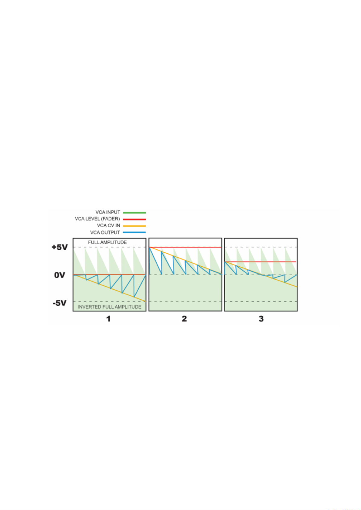
NOTE: Bi-polar VCAs invert the incoming signal when negative voltages are applied to the CV inputs. This is also
known as a thru-zero VCA or signal multiplier. Notice how the VCA LEVEL fader can be used to oset the CV level in
the images below.Take note of image 3 where the output goes silent as the CV crosses zero.
4
SHAPE
Voltage controlled wave shaper
Add harmonic complexity to your mix with wave folding and squaring
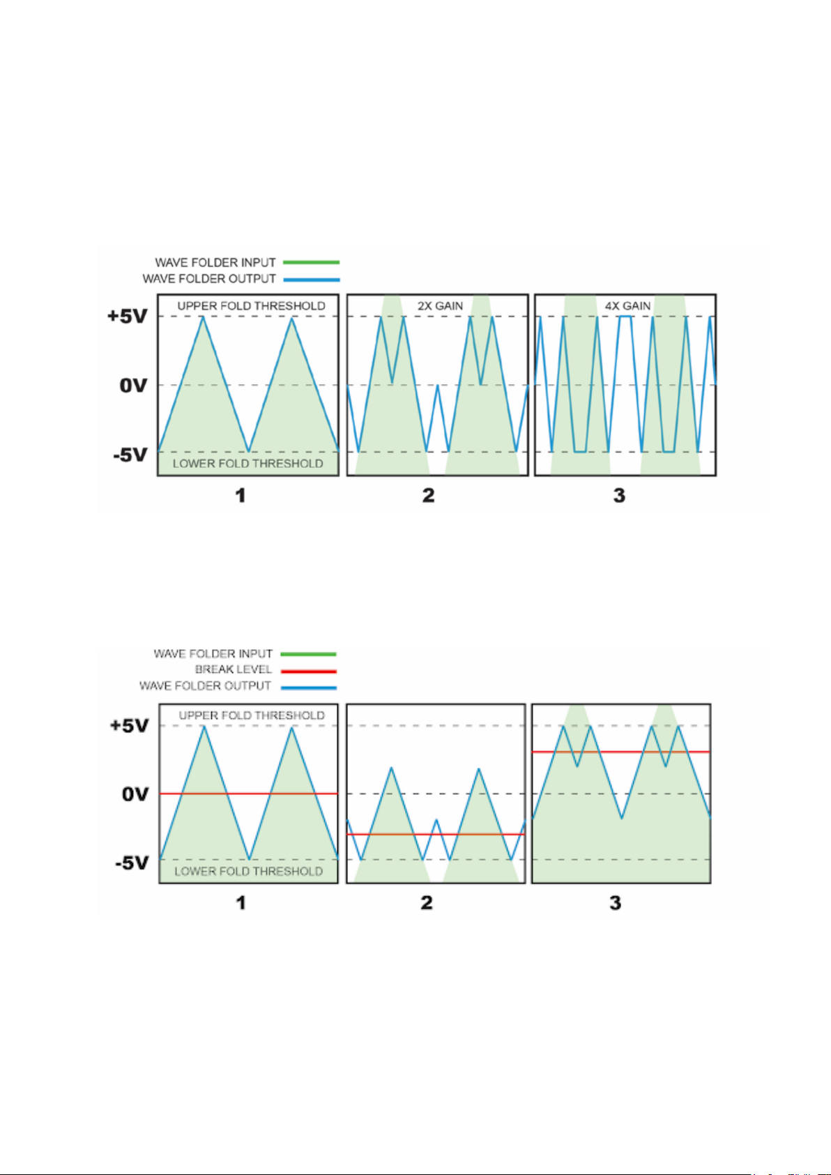
WAVE FOLDER
A, B, C and BREAK are mixed then passed on to the SHAPE section where the mixed signal passes through a wave-
folder. This function increases harmonic complexity by folding a wave form when it exceeds a given threshold. This
introduces high harmonic content and frequency multiplying eects. The diagram below shows how increasing the
amplitude of the incoming multiplies the signal frequency.
Wave folding can also be achieved by osetting the waveform with the Break level. This is similar to the eect above
but with a more subtle sonic eect. The drawing below shows the wave being oset up and down, in turn causing
the top and bottom peaks of the wave to fold.
5

SQUARE SHAPER
The output of the wave folder is routed to a square shaper stage that converts the waveform into a 3 step square
wave. This gives the sound a harder and harsher sound, but can also be used as a exible pulse width modulator
when processing simple waveforms.
BREAK
Signal disruption
Break has two modes, clipping and feedback which will disrupt your signal in dierent ways. Feedback mode is
activated by pressing the button marked “!”.
Clipping mode applies a DC oset to the mix pre-shaper. This can be used to oset the audio signal into a clipping
region where it becomes sonically thinner and quieter (see image below). You can think of this sort of like an inverse
VCA where applying voltage decreases the density and volume of the sound.
Feedback creates similar sound dissolving eects as well as distortion and input synced suboctave oscillation. In this
mode the square output of the shaper is looped back to the input of the mix via the break knob. External CVs can be
used to modulate the amount of feedback.
This image shows the input signal being negatively oset by adjusting the BREAK level in oset mode. This eect
can range from subtle to extreme depending on the amplitude of the incoming signal and the amount of oset ap-
plied.
6

QUICK START
How to make pulsing, mind melting drones
█Plug slightly detuned VCOs into A IN and C IN
█Create a sequence of gates to trigger a kick drum and 4 envelopes.
█Plug the kick drum into B IN and press the B PASS button.
█Plug rhythmically triggered envelopes into all other inputs.
█Play with all the levels.
█Press B PASS to rout the kick into the shaper section.
█Unplug the envelope from the break CV input. Adjust the break knob to hear how the drone
gets thinner and more distorted.
█Press the “!” button to activate feedback mode. This works best with steady drones so it may
be better if you turn down the modulation on A and C.
7
TIPS AND TRICKS
MAKE IT DRONE
█Plug 3 slightly detuned triangle wave oscillators into inputs A, B and C.
█Set the shape fader to ‘fold’.
█Play with the input levels and detuning of the oscillators to change the character of the drone.
█Plug rhythmically synced LFOs or envelopes into any or all of the CV inputs.
PULSE WIDTH MODULATION
█Set the shape fader all the way to “square” (to the right)
█Plug a triangle wave to input A. Play with the volume fader to change the pulse width.
█Adjust the BREAK knob while in offset mode (“!” light is off). This will change the pulse width in
a less pronounced way.
█Plug an envelope or LFO into C IN and adjust the C volume fader. The A, B and C inputs aren’t
only for audio and this patch makes it especially obvious why.
█Plug another envelope or LFO into A CV
VCA CV TRICKS
See the diagram above. Ponder the diagram above... This shows how the fader offset level affects the
behavior of the CV signal. If the offset fader is all the way down as it is in image 1 then the amplitude
will increase (albeit inverted) with a down sloping envelope. If the fader is UP (image 2) then the volume
will DEcrease with the same envelope. And if offset is in the middle you can get a decrease and then
increase with that same envelope. So you can change from a fade in to a fade out just by adjusting the
fader.
█Plug a VCO into A IN and a positive (uni-polar), repeating envelope into A CV.
█Set the fader all the way down and turn the A CV attenuverter halfway to the left. You will hear
the sound fade out with the envelope.
█Raise the fader all the way and you will hear the sound fade IN with the envelope.
█Set the fader in the middle to hear the interesting effect as the envelope goes above and
below zero.
8

CROSS FADING
The A CV input signal is normalized to the C CV jack. Both of these inputs are attenuverted so
by turning A CV knob right and C CV knob left you will be inversely modulating the amplitude of
inputs A and C which will result in crossfading your inputs.
█Plug two audio signals into A and C. Set A and C faders to the middle position.
█Plug an LFO or envelope to A CV. Adjust the A CV knob to the right of center. Adjust the C CV
knob to the left of center.
█The LFO can now be used to cross fade between input A and input C.
DUAL MODULATION EXTREME
Apply several levels of modulation to a single input signal. This trick sort of ipps the module on
its head. You will use A CV as your main audio in and A IN and C IN as CV inputs. It’s confusing
but it works and sounds great.
█Set SHAPE fader to ‘mix’.
█Plug two different LFOs or envelopes to A IN and C IN.
█Set A and C faders all the way down.
█Plug an audio signal into A CV. This will be normalized to C CV as well.
█Play with the A CV and C CV attenuverters to change the amount of modulation to the audio
signal.
█Now adjust the fader levels. This will add the IN signals to the main mix which will have a
strong effect on the signal when its folded. Try it.
RING MODULATION
Inputs A and C are fed through bi-polar VCAs. This means that if the CV input goes negative the
amplitude of the input signal will increase but will be inverted (as opposed to a standard VCA
which goes silent if the CV drops below zero).This is the function a ring modulation employs to
get its signature sound.
█Plug an oscillator or drum voice into input A and set fader A all the way down.
█Plug a simple waveform, like a sine wave, into A CV and turn the A CV attenuator up.
█You’re ring modulating now buddy.
TECH NOTE:
One thing to keep in mind that differentiates the WAVER VCAs from standard ring mods is that
the A and C faders are DC offsets for the VCAs (most ring mods have volume control for the input
but no amplitude CV offset control. I find this configuration a bit less intuitive but far more flexible
and useful). So even if you feed a negative voltage to CV jack, the offset level may keep the total
voltage from going negative. To achieve negative voltage modulation you may need to put the
fader all the way down to zero.
STEREO OUTPUT
Under the right conditions the SHAPE and MIX outputs can be used together to create interest-
ing stereo images. The key is to play with the BREAK and SHAPE settings. As these are adjusted
the stereo image will move and transform. Works especially well when audio signals are used to
plugged into the BREAK and SHAPE CV jacks.
9
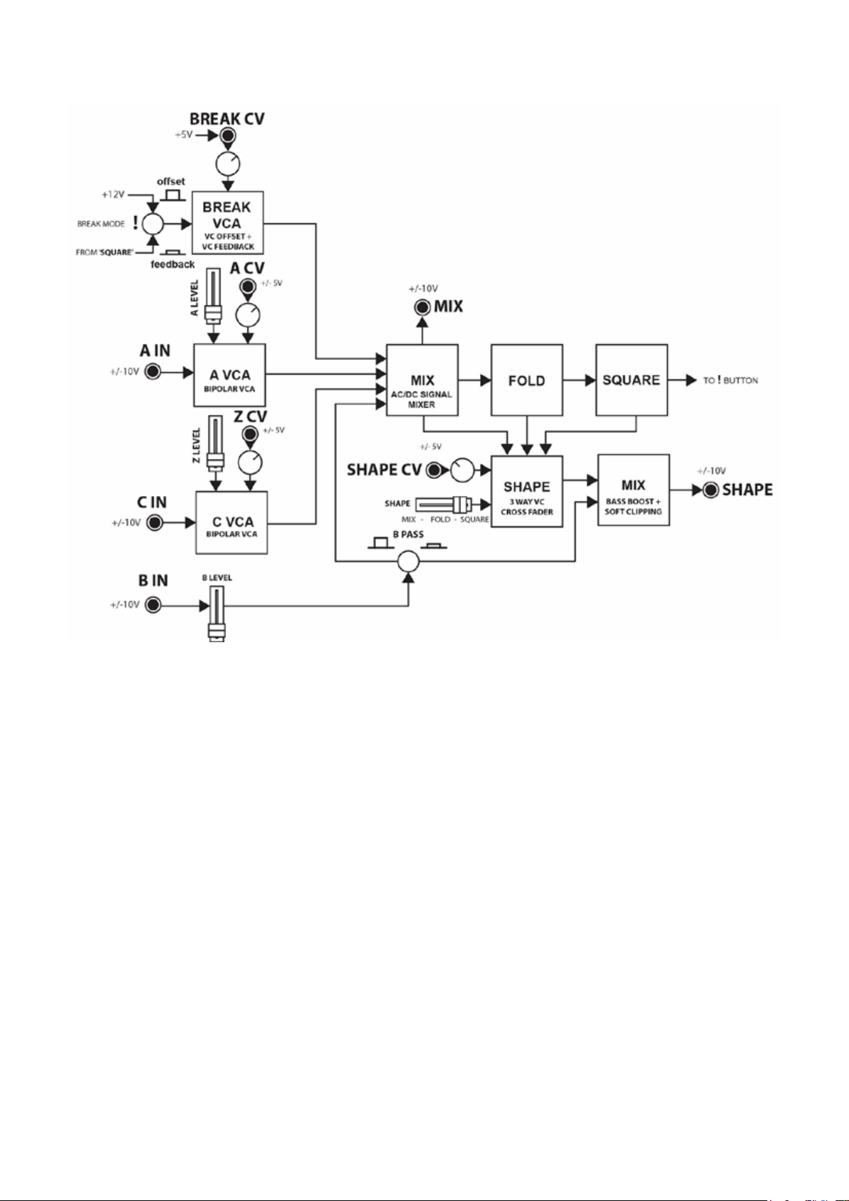
BLOCK DIAGRAM
10
Table of contents


