Yamaha MC802 User manual

YAMAHA
.
MC-Series
Mixing
Consoles
~~1,=a
=[:
:)(I
I)~
~¥~i"=
]~D~
~¥~i~
]~D~
Operating
Manual
I . .
MC1602 .

Congratulations!
You
are
the
proud
owner
of
a Yamaha MC-series Mixing Console. Whether
you
chose the
8,
12 or 16-channel model,
your
Yamaha
mixing
console
is
a high-quality
product that will give
you
superior perfonnance in
(l
wide range
of
applications.
In
addition to offering a versatile mixingsystem, the MC-series consoles
offer
electron-
ically balanced inputs and stereo outputs to maintain
optimum
signal quality over
long cable runs, a versatile 3-band equalizer with sweepable mid-frequency EQ on
each
input
channel, three independent A
UX
submix systems for external effects
routing
or
additional power amplifier feeds,
cue
switches
for
independent monitor-
ing
of
all
input
channels and busses, and a built-in talkback system
for
convenient
communication.
Of
course, the MC-series mixing consoles also
offer
(he high standard
of
quality and
great sound that Yamaha
is
famous for.
We
urge
you
to read this operation manual
thoroughly
in
order to
make
the
most
of
the mixer's
many
features
and
controls.
------CONTENTS------
PRECAUTIONS.
_. . . . . . . . . . . . . . . . . . . . . . .
..
2
FRONT
PANEL CONTROLS .
.........
.
..
, . .
..
3
Input Channels. . . . . . . . . . . . . . . . . . . . . . .
..
3
Master Control Section
...................
6
REAR PANEL CONNECTORS
AND
CONTROLS.
.
..
9
APPLICATION EXAMPLE
........
. .
...
....
. .
11
BLOCK
DIAGRAM
........................
12
LEVEL
DIAGRAM
.
........................
13
DIMENSION CHART .
......................
13
SPECIFICATIONS .
........................
14
SERVICE .
......................
.
......
,
15

PRECAUTIONS
1.
AVOID
EXCESSIVE
HEAT,
HUMIDITY,
DUST
AND
VIBRATION
Keep
the
unit
away
from
locations
where
it
is
likely
to
be
exposed
to
high
temperatures
or
humidity-such
as
near
radiators,
stoves,
etc.
Also avoid
locations
which
are
subject
to
excessive
dust
accumulation
or
vibration
which
could
cause
mechanical
damage.
2.
AVOID
PHYSICAL SHOCKS
Strong
physical
shocks
to
the
unit
can
cause
damage.
Handle
it
with
care.
3. DO NOT OPEN
THE
UNIT
OR ATTEMPT REPAIRS OR
MODIFICATIONS
YOURSELF
This
product
contains
no
user·serviceable
parts.
Refer
all
maintenance
to
qualified
Yamaha
service
personnel.
Open.
ing
the
unit
and/or
tampering
with
the
internal
circuitry
will void
the
warranty.
4. MAKE SURE POWER
IS
OFF
BEFORE
MAKING
OR
REMOVING
CONNECTIONS
Always
turn
the
power
OF
F
prior
to
connecting
or
dis·
connecting
cables.
This
is
important
to
prevent
damage
to
the
unit
itself as well as
other
connected
equipment.
5.
HANDLE
CABLES
CAREFULLY
Always
plug
and
unplug
cables-including
the
AC
cord-by
gripping
the
connector,
not
the
cord.
6. CLEAN
WITH
A SOFT
DRY
CLOTH
Never
use
solvents
such
as
benzine
or
thinner
to
clean
the
unit.
Wipe
clean
with
a
soft,
dry
cloth.
7. ALWAYS USE
THE
CORRECT POWER SOURCE
Make
sure
that
the
power
source
voltage
specified
on
the
rear
panel
matches
your
local AC
mains
supply.
U.S. &
Canadian
Models:
120V
AC,
60Hz
General
Model:
110
-
120/220
-
240
V
AC,
50/60Hz
2

RONT PANEL CONTROLS
--:
:.----
I
nput
Channels
---
o
PAD
Switch
This
switch
attenuates
the
signal
applied
to
the
corresponding
rear
-
panel
HI-Z
or
LO-Z
input
by
20
dB
prior
to
the
head
amplifier
and
input
gain
control.
The
PAD
switch
effectively
increases
the
range
of
input
signal levels
that
can
be
handled
by
the
mixer,
preventing
overloading
of
the
input
circuitry
when
receiving high-level signals_
f)
GAIN
Control
This
control
adjusts
the
input
sensitivity
of
each
input
channel
between
-60
dB
(0.775
mV)
and
-20
dB (77.5 mV)
when
the
PAD
switch
is
OFF
(between
-40
dB
and
0
dB
when
the
PAD
switch
is
ON).
Continuously
variable
gain
control
allows
optimum
matching
with
virtually
any
microphone
or
line
source.
~
CLIP
LED
Indicator
The
CLIP
indicator
LED lights
when
the
post
-
EO
signal
of
the
corresponding
channel's
input
reaches
a level 3
dB
below
the
clipping
level
of
the
channel's
circu
i
try.
If
the
CLIP
indicator
lights
more
than
only
briefly
on
high
-level
transients
it
is
necessary
to
decrease
the
input
sensi-
tivity
of
the
channel
using
the
GAIN
control
and
PAD
switch
or,
if
this
does
not
provide
sufficient
attenuation,
to
reduce
the
output
level
of
the
source
connected
to
that
channel's
input.
o
3-band
Equalizer
The
equalizer
section
provided
on
each
input
channel
comprises
shelving
LOW
and
HIGH
con-
trols
,
and
a
peaking
MID
control
with
a MID
FREO
control
that
permits
sweeping
the
midrange
center
frequency
from
350
Hz
to
5
kHz
.
Control
Ma)(imum
Frequenc8
Tvpe
Boost/Cut
HIGH
±15dB
10kHz
Shelving
MID
±l5dB
0.35
- 5
kHz
Peaking
LOW
±l5dB
100Hz
Shelving
l .
FR
Q
~
V
·
'0
"-
'\. ;
-
r
V.
_
\.
IX/
I
~
,
..
-. x:
-_
\.
L
/
'\.
-V \ ,
- 10
'"
-
•
~
10 1
00
1
0.
rAEOUENCY(~11
3

" AUX Controls
(1,2
&
31
The MC-series mixing consoles have three independent AUX busses which are fed by the
corresponding AUX
controls
on the
input
channels_ Each AUX
control
determines
the
level of
the
signal sent from
that
channel to
the
correspondingly numbered AUX mixing buss, which in
tum
feeds the correspondingly
numbered
AUX SEND control and AUX SEND jack on the
console's rear panel.
The
AUX controls can be used
to
determine the
amount
of
signal from the
corresponding input channel sent
to
external effect devices
or
power amps fed by the AUX
SEND
jacks_
• AUX 1
is
factory pre-wired for pre-EO/pre-fader operation, so the AUX 1 signal
is
not
affected by the setting of the channel EO controls
or
fader_ An internal jumper allows the
AUX 1 control
to
be rewired for post-EO/post-fader operation_
* AUX 2 and AUX 3 are factory pre-wired for post-EO/post-fader operation, so the AUX 2
and AUX 3 signals are affected by
the
setting
of
the
channel EO controls and fader_Internal
jumpers aI/ow the AUX 1 control
to
be rewired for pre-EO/pre-fader operation_
• An internal POST EO jumper allows the AUX controls to be' further re-configured for
post-EO/pre-fader operation_
• REFER THE ABOVE-MENTIONED REWIRING JOBS TO OUALIFIED YAMAHA SER-
VICE PERSONNEL!
o PAN Pots
The
PAN
pot
determines the position
in
the stereo sound field
at
which the
sound
from
that
channel
is
heard_
Rotated
fully counterclockwise the channel signal will be delivered from the
left stereo
output
only, and will be heard
at
the far left of the sound
field_
If
the
PAN
pot
is
turned fully clockwise, the sound from
that
channel will appear
at
the far right
of
the stereo
sound field. If the
PAN
pot
is
set
at
its
center
position, the channel signal will be
sent
equally
to
both the left and right channels, causing the sound
to
appear at
the
center
of the sound
field_
Intermediate
PAN
pot
settings cause
the
sound
to
be heard
at
the corresponding position,
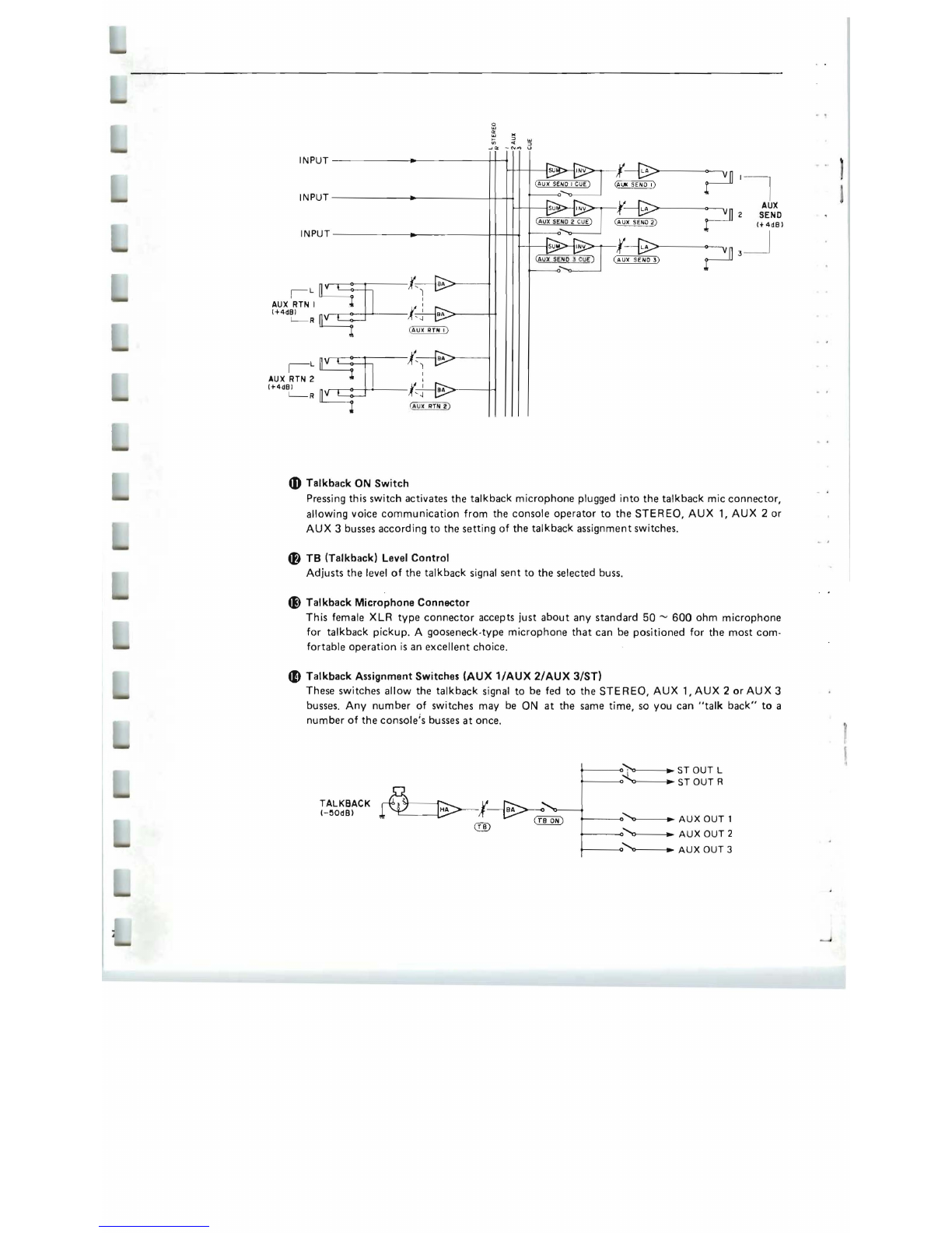
8 CUE Switch
When the
CUE
switch
is
pressed, the pre-EO/pre-fader signal from
that
channel
is
fed
to
the
PHONES
output
via
the CUE/PHONES level cOrltrol. The channel cue signal will be added
to
any
other
active cue signal.
If
you
want
to
monitor
only the signal from a single channel, make
sure
all
other
CUE
switches are turned OFF_
4

o Channel
Fader
This
is
the
main
level
control
for
each
input
channe
l.
It
determines
the
level
of
the
signal
sent
from
the
corresponding
input
channel
to
the
master
stereo
buss.
The
settings
of
the
input
channel
faders
determine
the
"mix"
or
balance
of
sound
levels
between
the
instruments
or
other
sources
connected
to
the
inputs.
*
If
a
channel
is
not
being
used,
its
fader
should
be
set
to
the
minimum
position
to
prevent
unwanted
noise
from
being
added
to
the
main
program
signal.
,48V
0
CC
'"
'"
"
::>
>-
r--LO
Z
CH
VI
::>
...lCC
-N",
IN/OUT
(-6dB)
~
20
dB
@ill)
'"
INPUT
CH
INSERT
""
U
Mca
02
INPUT MCI2
02
LCI602
HI Z
LO
lli
MID
HIGH
V
~(_M_ID
__
_
____
~~~~_-
~--~~~~~
FR_E_Q
)
{@
f~f-+-+~

---
Master Control Section
---
~~
I
1
~
J I 0
OP(A
I'I..
-~+
vu
AU
X/C
UE
1
7
!)
3 1 0 0 PE
A.l(,
-~+
~
..
vu
>0
~.
- +
vu
L ST R
a
EJ
a
G
METER
o
10
..
AUX
SEND1
..
10
10
o AUX SEND
(1.2
& 3) Controls & CUE Switches
These adjust the overall
output
level
of
the
auxiliary
"mixes"
set up using the AUX 1, AUX 2 and AUX 3 con-
trols on the
input
channels. AUX SEND 1 sets the overall
level of the AUX 1
mix
signal appearing
at
the AUX
SEND 1 jack, AUX SEND 2 sets the overall level of the
AUX 2 mix signal appearing at the AUX SEND 2 jack,
and AUX SEND 3 sets the overall
level
of the·AUX 3
mix appearing
at
the AUX SEND 3 jack. These controls
should be used
to
optimally match
the
AUX SEND out-
put
level of the mixing console
to
the
input
sensitivity
of
the effect unit, signal processing device or amplifier used.
The
CUE
switches associated with each AUX SEND con-
trol can
be
used
to
send the corresponding AUX SEND
signal to the PHONES jack
via
the CUE/PHONES level
control. The A
UX
cue signal will be added
to
any
other
active cue signal. If you
want
to
monitor only
the
signal
from a single AUX buss, make sure
all
other
CUE switches
are turned 0 F
F.
4m)
AUX RTN 1 & AUX RTN 2 Controls
These controls adjust the level
of
the signal received
at
the
rear-panel AUX
RTN
jacks and mixed into the main
stereo program. Since stereo AUX returns are provided
(AU X
RTN
1 L &
R,
AUX RTN 2 L &
R)
the
AUX RE·
TU RN controls simu Itaneously .adjust the level of the
signals appearing
at
the corresponding
Land
R return
inputs. The returned
Land
R channel signals are
sent
to
the
Land
R stereo buss lines. If only a single-channel
signal
is
returned
(i
.e. a plug
is
inserted into only the L or
R return jack), the signal will be fed
to
both
the
Land
R
channels of the stereo buss.
R
PHONES
L
STERE
O
6

4D
Talkback
ON
Switch
Pressing this swi
tch
activates
the
talkback
microphone
plugged
into
the
talkback
mic
connector,
allowing voice
communication
from
the
console
operator
to
the
STEREO,
AUX 1, AUX 2
or
AUX 3 busses
according
to
the
setting
of
the
talkback
assignment
switches.
4B
TB (Talkback) Level
Control
Adjusts
the
level
of
the
talkback
signal
sent
to
the
selected buss.
~
Talkback
Microphone
Connector
This
female XLR
type
connector
accepts
just
about
any
standard
50
-
600
ohm
microphone
for
talkback
pickup
. A
gooseneck-type
microphone
that
can
be
positioned
for
the
most
com-
fortable
operation
is
an
excellent
choice
.
4D
Talkback
Assignment
Switches
(AUX
1/AUX
2/AUX
31ST)
These
switches
allow
the
talkback
signal
to
be fed
to
the
STEREO,
AUX 1, AUX 2
or
AUX
3
busses.
Any
number
of
switches
may
be ON
at
the
same ti
me,
so
you
can
"talk
back"
to
a
number
of
the
console's
busses
at
once
.
~--~~~--~
••
STOUTL
t------<;-l;,
~
STOUT R
TALKBACK
(
-
~OdB)
~1~'-
~
® (
TO
ON)
t-------<>
...
-----I.~
AUX
OUT
1
~--~:--..,
~
AUX
OUT
2
~----O~
~
AUX
OUT
3
INPUT--
----
------.-
----
------rr1
INPUT-----------4~--------
_+
~
INPUT------------.---
--
------~444
BO>-----+1
r--L
n~.t
~
~
BA
AUX
RTN2
~
:
(t4dB)
~
JI
I
BA>------+-i
'---
R
,
F~
~
1~
~
mi
l
v
-----I.:?-----
-A
UX
"'~02
SEND
(
AU
'
SEND
2)
r--
(t4dB)
(
r.~n'
~

r -
r
~
VU Meters
and
METER Assign Switches (AUX
1/AUX
2/AUX
3/CUE)
The
MC-series mixi
ng
console
feature
three
VU
meters
wi
th
built
-
in
LED peak indicators for
monitoring
signal levels.
The
rightmost
meter
pair (L ST
R)
continuously
monitors
signals
on
the
main
stereo
program buss.
The
AUX/CUE
meter
can
be switched
to
monitor
signals on
the
AUX 1, AUX 2, AUX 3
or
CUE busses by pressing
the
corresponding
METER assign
switch.
'"
::>
u
INPUT
-
-------1
(METER)
AUXSEND1--
-
_---~
AUXSEND2-
--_--
-~
AUXSEND3-
-
-_----~
AUX
I
4D
CUE/PHONES
Control
and
PHONES
Jack
The
CUE/PHONES
control
adjusts
the
level
of
the
cue signal
sent
to
the
PHONES jack so you
can
set
the
most
confortable
headphone
monitoring
level. The stereo
phone
jack
accepts
any
standard
stereo
headphones
.
*
The
STEREO
cue signal appears
in
stereo
at
the
phones
jack, while
the
channel
and
AUX
cue
signals are monaural.
"'
::>
u
'"
::>
u
oJ'"
INPUT
---
....
----1
STOUT_
....
---f-1
AUX
SEND
1-
-
-_
-
---t
AUXSEND2----
--
--t
AUXSEND3--------t
f~
1
!
A~
PHONES
t H '
jl '
....
~
(CUE/PHONES )
4D
STEREO
CUE Switch
Turning
this switch
ON
sends
the
main
stereo
program buss signal,
in
stereo,
to
the
stereo
PHONES jack
~
i
a
the
CUE/PHONES
control.
The
STEREO
CUE switch can normally be
turned
ON
to
permit
headphone
monitoring
of
the
main
stereo
program,
but
it must be
turned
OFF
to
individually
monitor
input
channel
or
AUX buss
cue
signals,
8

4E)
STEREO
Master Faders
The
STEREO master faders independently adjust
the
level of the left and right channel main
stereo program buss signals appearing
at
the
STER
EO
OUT connectors.
'"
~
~
ST
L
V>
-''''
INPUT
Ll
AUX
RTN 1
ST
F1
ST
OUT
AUX
RTN 2
1+4dB)
ST
SUB
IN
RJ
REAR
PANEL CONNECTORS
AND
CONTROLS
U,S
, & Canadian models
9

41>
POWER
Switch
Flip
up
to
turn
power
ON,
and
down
to
turn
power
OFF.
The
VU
meter
lamps
will light
when
the
power
is
ON.
~
PHANTOM
MASTER
Switch
Turn
this
switch
ON
to
apply
+48
volts
De
to
the
LO·Z
XLR
input
connectors
when
using
phantom·powered
condenser
microphones.
*
NEVER
turn
the
PHANTOM
MASTER
switch
ON
when
applying
line·sources
to
the
LO·Z
inputs.
~
HI-Z
and
lO-Z
Input
Connectors
Each
input
channel
offers
a
choice
of
two
input
connec-
tors:
a
balanced
LO·Z
(low-impedance)
XLR-type
connec-
tor
and
a HI·Z
(high.impedance)
tip-ring·sleeve
1/4"
phone
jack.
The
LO-Z
inputs
are
primarily
intended
for
use
with
professional
low-impedance
microphones
or
electronic
instruments
having
low·impedance
balanced
outputs.
The
HI-Z
inputs
will
accept
either
balanced
or
unbalanced
signals
from
high.impedance
microphones,
musical
instruments
or
other
source
equ
ipment.
o INPUT CH
INSERT
IN/OUT
Jacks
These jacks
permit
inserting
compressors,
limiters
or
other
types
of
external
signal
processing
equipment
between
the
head
amplifier
and
EO stage
of
each
input
channel.
The
jacks
are tip-ring-sleeve
types
in
which
the
tip
is
SEND
(the
output
from
the
head
amplifier),
the
ring
is
RETURN
(the
input
to
the
EO
stage),
and
the
sleeve
is
ground.
External
equipment
may
be
inserted
using
"Y"
cables
which
branch
the
SEND
and
RETURN
lines
from
a
tip.
ring·sleeve
phone
plug
to
two
separate
mono
phone
plugs.
INSERT
OUT
(tip)
/
C!JI
{\
II
INSERT
IN
(ring)
fJ)
AUX
SEND
(1,2
&
3)
Jacks
These
jacks
deliver
th~
AUX
1,
AUX
2
and
AUX
3 mixes,
respectively,
to
feed
an
external
effect
device
or
power
amplifier.
Nominal
output
level/impedance
is
+4
dB/
600
ohms
.
~
AUX
RETURN
1
(l
& R) &
AUX
RETURN
2
(l
& R)
Jacks
The
mono
or
stereo
output
from
effect
units
fed
by
the
AUX
SEND
jacks
can
be
returned
to
the
main
stereo
program
mix via
these
jacks
.
Note
that
each
AUX
RE-
TURN
offers
independent
return
inputs
for
the
left
and
right busses,
accommodating
the
return
signal
from
effect
units
featuring
stereo
outputs.
Nominal
input
level/im-
pedance
is
+4
dB/600
ohms.
~
AUX
SUBIN
&
ST
SUB
IN
Jacks
These
five
jacks
permit
"cascading"
two
Me-series
mixing
consoles
to
increase
the
number
of
available
input
chan·
nels.
The
AUX
OUT
jacks
from
the
first (slave)
console
should
be
connected
to
the
corresponding
AUX
SUB
IN
jacks
of
the
second
(master)
console,
and
the
STEREO
outputs
from
the
slave
console
should
be
connected
to
the
corresponding
ST
SUB
IN
jacks
on
the
master
console.
~
STEREO
OUT
l & R
Connectors
The
Me-series
mix ing
consoles
provide
balanced
XLR
con·
nector
outputs
from
the
main
stereo
buss.
The
signal
delivered
is
a
stereo
mix
of
the
input
channel
signals
and
the
signals
returned
to
the
AUX
RETURN
jacks.
The
STE
REO
OUT
signal will
normally
be used
to
drive a
power
amplifier
and
speaker
system,
powered
keyboard
speakers
or
a
main
house
mixing
console.
Nominal
output
level/load
impedance
is
+4
dB/600
ohms.
NOTE:
The
Me-series
mixing
console
X
LR
connectors
are
wired
according
to
DIN
specifications.
Pin 1
is
shield
(ground),
pin
2
is
hot
(signal high)
and
pin 3
is
cold
(signal
lowl.
10

APPLICATION EXAMPLE
In
the
system
shown
below
the
MC1602
is
used
as
the
main
console
in a
sound
reinforcement
system.
Three
vocal micro-
phones,
six
drum
microphones,
a
microphone
from
the
guitar
amplifier
and
another
from
the
bass
amplifier
are
connected
to
11
of
the
16
available LO-Z
inputs
.
The
line-level
stereo
outputs
from
an
on-stage
keyboard
mixer
and
the
stereo
outputs
from
an
electronic
percussion
system
are
fed
to
four
HI-Z
inputs.
A
total
of
15
input
channels
are
thus
used,
leav-
ing
one
free -
just
in
case.
The
AUX
1 mix
system
feeds
on-stage
power
amplifiers
and
monitor
speakers
for
the
STAGE
MONITOR
SPEAKERS
performers.
The
AUX
2
system
is
used
to
drive a digital .
.,
reverb/effects
u
nit
to
add
ambience
and
effects
where
neces-
sary.
The
AUX
3
system
feeds a
tape
recorder
to
make
a
rough
mono
recording
of
the
performance.
The
STEREO
OUT
connectors
drive
the
main
house
power
amplifiers
and
speaker
system.
This
is
just
one
possible
way
of
setting
up
the
MC1602
for
a
sound
reinforcement
application.
The
actual
setup
you
use
will,
natu
rally.
be
dictated
by
your
own
particu
lar
system
requirements
.
POWER
AMP
DIGITAL
REVERB/
EFFECT
UNIT
o@o
D
ST
OUT
L
AUX
SEND
1
TAPE
RECORDER
'--y-J
'-r'
STEREO
OUT
FROM
KEYBOARD
MIXER
STEREO
OUT
FROM
ELECTRONIC
PERCUSSION
SYSTEM
"---y--I
VOCAL
MICS
ELECTRIC
GUITAR
AMP MIC
ELECTRIC
BASS
AMP
MIC
HOUSE
SPEAKER
SYSTEM
11

BLOCK
DIAGRAM
t48
v
r
LO
Z INPUT
CH
INSERT
CH
"C8
02
IN/OUT
,-
6d8
1
INPUT
=~:~~~
HI
Z
-::-+:
==
~
gJ;"
u
w
"
HL
5TEOE~L
ADER 0
I LA "
ST • ST OUT
srE.E~.
t+4dB)
0
LO'W
MID
HIGh
(MID
FREQ r
rAoER
J
V " R
,.,
-
LA
(
CH
CUE
)
~
r--
L
AUX
RTN 2
1+4dB)
~
R
8A.:;>
----
-
--
-
-l
?'
I
~
__
~~~__
AUX
~n
2 SEND
r-
It4dBI
?,
_i
i L
STSUBIN
lt4dB)
~
R
i
AUX
'
AUX
SUB
IN AUX 2
1+4dB)
L AUX 3
TALKBACK g -
y~
1-50dB)
~;f.
~
~
""'
------
-*,f--,H-i
l~
®
@W
1
¥~npHONES
t~~
(C
UE/PHONE
S)
12

LEVEL
DIAGRAM
PAN
STEREO
URI
FADER
-.
DIMENSION
CHART
J
I MC802 :
4~01l7-3/4'1
r-
..
r---
-
----MC
1202
:
~90(23
-
1/4
'I
- -
-------c
..
..,1
MCI602
:
730(28-3/4"
. j
"ID
....
...
,
0
N
;;;
on
"<D
on
Q Q 0 0 0 0 0
.-
Q Q 6 q
.Q
0 0
0 q 0 Q 9 Q 0 0 0
P b b
9-
<>
Q 0 0
°1
-'
-'
0 6 0
<>
0 0 0 0
@2l
0 0
0 0 q 0 9 0 0 0
-'
0 0 0 q 0 q 0 0 0 0 0
0 o. 0 Q 0 Q 0 0 0
0 6 ° b ° Q 0 0 0 0 0 0
0
.:;
-'
@
Unit
:
mm
(Inch)
13

SPECIFICATIONS
Total
Harmonic
Less
th
an 0 .1%,
20H
z -
20kHz@+14dB
Distortion
into
600
ohm
s.
Frequency
Response
+1,
-
3dB
.
20H
z -
20kH
z @
+4dB
into
600
ohm
s
Hum
and
Noise'
(20Hz
-
20kHz,
Rs=150
ohms,
Input
Gain
max
.,
Input
Pad @OdB,
Input
Sensi
tivity
~OdBI
-128dB
-92dB
-72dB
-64dB
-67dB
-64dB
equiva
l
ent
input
noise.
res
i
du
al
output
noise (balanced
outputs)
.
at
STEREO
OUT
wi
th
master
fader
at
nominal
level
and
all
cha
nnel
fad
e
rs
at
min
i
mum
le
vel.
at
STEREO
OUT
with
master
fader
and
one
channel
fader at
nom
i
na
l level
at
AUX
SEND
with
AUX
SEND
level
control
at
nominal
level
and
all
channel
AUX
controls
at
minimum
level.
at
AUX
SEND
with
AUX
SEND
and
one
AUX
control
at
nom
inal
leve
l.
Maximum
Voltage
Gain
84dB
CH
IN
to
STEREO
OUT
84dB
CH
IN
to
AUX
SEND
1
94dB
CH
IN
to
AUX
SEND
2,
3
20dB
AUX
RETURN
1,2
to
STEREO
OUT
10dB
SUB
IN
to
AUX
SEND
1 - 3
10dB
SUB
IN
to
STEREO
OUT
Input
Channel
Gain
Control
-
20
-
-60dB
variation
in
gain,
stop
to
stop
.
Input
Channel Pad
Switch
0/20dB
of
attenuation
.
Input
Channel
Equalization
15dB
maximum
boost
Or
cut
in each
of
three
bands.
HIGH
:
10kHz
(shelving)
MID:
350Hz
-
5kHz
(peaking)
LOW
:
100Hz
(shelving)
Crosstalk
-60dB
at
lkHz,adjacent
input
channels.
-GOdB
at 1
kHz,
input
to
output
.
VU
Meters (0
VU
=
+4dB
Output)
3
illuminat
ed meters.
STEREO
L,
STEREO
R,
AUX
l /
AUX
2/
AUX
3/
CUE
(swi
tchable)
Clip
Indicators
RED
LED
built
into
each
input
c
hannel.
Lights
when
post·EO
channel signal
is
3dB
below
clipping
level .
Phantom
Power
+48
VDC
applied
to
electronically
balanced
inputs
via
6.8
k-<>hm
limiting
resistors. Master
ON/OFF
switch
.
Power
Requirements
U .S.
8.
Canadian
models
:
120V
AC
,
60Hz
General
model
:
110-
120
/
220
-
240V
AC
,
50
/
60Hz
Power
Consumption
MC1602
:
60
watts
MC1202
:
50
watts
MC802
:
40
watts
Dimensions
(W
x H x
D)
MC1602
:
730
mm
x 151
mm
x 531
mm
(28
-3/4" x 6" x
20
-
7/8")
MC1202
:
590
mm)(
151
mm)(
531
mm
(23
-1/
4")(
6")(
20
-7/
8")
MC802
:
450
mm)(
151
mm)(
531
mm
(17-3
/4 "
)(
6")(
20
-7/
8")
Weight
MC1602
:
18
kg.
(39
.7 Ibs.l
MC1202
:
15
kg.
(33
.1 Ibs.l
MC802
:
12
kg_
(26.4
Ibs.l
• Measured
with
.a -
6dB
/
octav
e
LPF
@
12
.
7kHz
.
.0dB
= 0.
775Vr
.m
.s.
•
Specifications
subject
to
change
without
notice
.
14

•
INPUT
CHARACTERISTICS
INPUT
INPUT
LEVELS
INPUT
SOURCE
SENSITIVITY'
•
MAXIMUM
CONNECTOR
PAD
GAIN
IMPEDANCE
IMPEDANCE
RATED
LEVEL
NON
CLIPPING
TYPE
LEVEL
-
60dB
50~600
ohms
-80dB
(0.08mV)
-60dB
(0.8mV)
-34dB
(15.5mV)
XLR-3
-
31
type
OFF(OdB)
LO
·Z
4k
ohms Microphones (Balanced)
CHINPUT
-4OdB
(7 .
75mV)
-20dB
(77
.5mV)
+6dB
(1.55V)
and
20dB
HI
·Z
10k
ohms
or
Phone Jack
(TRS)
ON(2OdB)
600
ohms Lines
-2OdB
(77.5mV)
OdB
(775mV)
+26dB
(15.5V)
(Balanced)
INPUT
CH
INSERT
IN
10k
ohms
600
ohms Lines -
26dB
138.8mV)
-6dB
(388mV)
+20dB
(7.75V)
Phone Jack
(TRS)
(Unbalanced)
ST
SUS
IN,
AUX
SUS
IN
10k
ohms
600
ohms Lines
-6dB
(388mV)
+4dB 11.23V)
+20dB
17
.
75V)
Phone Jack
(Unbalanced)
AUX
RTN
10k
ohms
600
ohms Lines
-16dS
(123mV)
+4dB
(1
.
23V)
-Phone Jack
(Unbalanced)
TALKSACKIN
4k
ohms
50
~600 ohms
-70dB
10
.
25mV)
-50dB
(2.45mV)
-24dB
(48.
9mV)
XLR-3-31
type
Microphones IUnbalanced)
•
OUTPUT
CHARACTERISTICS
OUTPUT
OUTPUT
IMPEDANCE
LOAD
IMPEDANCE
OUTPUT
LEVELS
CONNECTOR
TYPE
RATED
LEVEL
MAXIMUM
NON·
CLIPPING
LEVEL
STOUT
150
ohms
600
ohms Lines +4dB 11.23V)
+24dB
(12.3V)
X
LR
-3-32
type
IBalanced)
AUX
SEND
1-3
150
ohms
600
ohms Lines +4dB
(1
.
23V)
+20dB
(7.75V)
Phone Jack
(Unbalanced)
INPUT
CH
INSERT
OUT
600
ohms
10k
ohms Lines
-6dB
(388mV)
+20dB
(7.75V)
Phone Jack
ITRS)
(Unbalanced)
8 ohms Phones
lmW
20mW
Stereo Phone
Jack
(Unbalanced)
PHONES
100
ohms
40
ohms Phones 3mW
130mW
••
Input
level required
to
produce rated
+4dB
output
level .
•
OdS
~
0.
775Vr.m
.
s.
SERVICE
This
product
is
supported
by
Yamaha's
worldwide
network
of
factory
trained
and
qualified
dealer
service
personnel.
In
the
event
of
a
problem,
contact
your
nearest
Yamaha
dealer.
YAMAHA
HAMAMA
TSU,
JAPAN
is
8709
r:I
Printed
in
Taiwan
Other manuals for MC802
3
This manual suits for next models
2
Other Yamaha Music Mixer manuals

Yamaha
Yamaha DM 2000 Version 2 Firmware update

Yamaha
Yamaha MC802 User manual

Yamaha
Yamaha EM-1620 User manual

Yamaha
Yamaha 03D User manual

Yamaha
Yamaha MG124CX User manual

Yamaha
Yamaha IM8-40 User manual

Yamaha
Yamaha EMX620 User manual

Yamaha
Yamaha MG Series User manual

Yamaha
Yamaha M7CL StageMix V1.5 User manual

Yamaha
Yamaha MG206C User manual

Yamaha
Yamaha DS2416 User manual

Yamaha
Yamaha EMX3500 User manual

Yamaha
Yamaha MG10 User manual

Yamaha
Yamaha TF5 User manual

Yamaha
Yamaha Ncs500-FD User manual

Yamaha
Yamaha RIVAGE PM10 User manual

Yamaha
Yamaha PM3500M User manual

Yamaha
Yamaha MG10 User manual

Yamaha
Yamaha PM5D User manual

Yamaha
Yamaha MW10 Assembly instructions