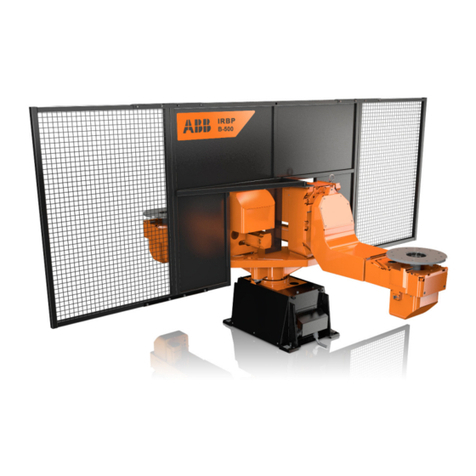
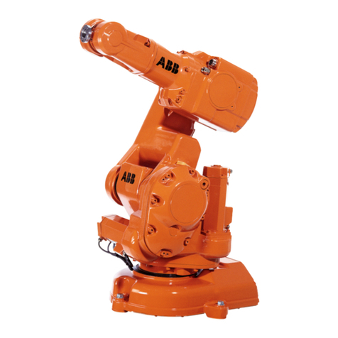
Battenfeld UNIROB R8 User manual

Operating Manual
UNIROB R8 – UNILOG B2
Version R82GBV00 04/03
Read before using the robot and
keep it near the robot for reference purposes.
Robot - Type R8 / B2 6-10-20
Controller type UNILOG B2
Robot No.: 26358
Model: 2003

Battenfeld GmbH
Scherl 10 • D-58527 Meinerzhagen
Tel. ++49 2354/72-0 • Fax ++49 2354/72-234
Battenfeld Kunststoffmaschinen Ges.m.b.H.
Wr.Neustädter Straße 81• A - 2542 Kottingbrunn
Tel. ++43 2252/404-0 • Fax ++43 2252/404-261
www.battenfeld.com
DIN EN ISO 9001
Injection moulding
R82GBD1A.PMD

Index
A:PB2GBI1A.P65
B: PB2DEI1A.P65
E: 180202 / Ruder
G: 190202 / G. Krajnik
Section - IN1
Page - 1
Chapter 1 General information
Chapter 2 Safety
Chapter 3 Technical Data
Chapter 4 Transport - Installation
Chapter 5 Structure and function
Chapter 6 Comissioning
Chapter 7 Maintenance
Chapter 8 Spares / Plans
Chapter 9 Customer service
Chapter 10 Extra chapter for special modules
?
0

A:PB2GBI1A.P65
B: PB2DEI1A.P65
E: 180202 / Ruder
G: 190202 / G. Krajnik
Section - IN1
Page - 2
Index

Table of contents
A: R82GBI2A.PDM
B: R82DEI2A.PDM
E: 080403 / T. Wenger
G: 020403 / TCS
Section - TC
Page 1
1.0 General
1.1 Introduction
1.2 Use
1.3 Symbols
1.4 Copyright
1.5 Confirmation of receipt
1.6 Declaration of Conformity
2.0 Safety
2.1 Safety regulations
2.1.1 General
2.1.2 Installation
2.1.3 Operation and maintenance
2.1.4 Safety - Personnel
2.1.5 Safety regulations –
Pneumatic systems
2.1.6 Safety regulations –
Electrical systems
3.0 Specifications
3.1 Machine description
UNIROB B2 industrial robot
3.1.1 Kinematics
3.1.2 Handling loads
3.1.3 Mechanical interface
3.1.4 Delivery side selection
3.2 Robot axles
3.2.1 Linear axles
3.2.2 Auxiliary axes
3.3 Performance data /
Mechanical interfaces /
Technical features
3.3.1 Linear axes (main axes)
Main axis paths – Axis
lengths
3.3.2 Drives / Repeat accuracy
3.3.3 Maximum speeds of main
and linear axes
3.3.4 Maximum speeds of rotating
and auxiliary axes
3.4 Pneumatic system
3.4.1 Compressed air connection
3.4.2 Creating a vacuum
3.4.3 Pneumatic valves
3.4.4 Pressure monitoring
3.4.5 Central configuration
3.5 Guideways on main axes
3.6 Motors / Gearing
3.6.1 Maintenance-free servo
three-phase a.c. motors for
main linear axes
3.6.2 Planetary gearing for the X
(Z) and Y and Z axis drive

A: R82GBI2A.PDM
B: R82DEI2A.PDM
E: 080403 / T. Wenger
G: 020403 / TCS
Section - TC
Page 2
Table of contents
3.7 Drive elements on main axes
3.7.1 X + Z-axis
3.7.2 Y-axis immersion pipe
3.8 Mechanical interface
3.8.1 Gripper interfaces
3.8.2 Manual gripper quick change
3.9 R8/B2 robot options
3.10 EUROMAP 12
3.10.1 Robot / Injection moulding
machine interface
3.10.2 Injection moulding machine
signals
3.10.3 Handling device signals
4 Transport - Installation
4.1 General
4.1.1 Storage
4.1.2 Unloading
4.1.3 Securing devices
4.1.4 Crane transportation
4.1.5 Transport weight
4.1.6 Injection moulding machine
assembly
4.1.7 Installation layout
4.1.8 External stand
4.1.9 Removing protective
coatings
4.2 Connecting to the power
supply
4.3 Commissioning
4.3.1 Connecting to the power
supply
4.3.2 Harting connector
4.3.3 Lubrication points
4.3.4 Compressed air supply
4.3.5 Activating the main switch
4.3.6 EMERGENCY STOP test
4.3.7 Power ON
5 Assembly and Operation
5.1 Modules
5.2 Pneumatic system
5.2.1 Directional control valves
5.2.2 Vacuum suction nozzle
5.2.3 Cleaner
5.3 Electrical systems
5.3.1 Electric motors
5.3.2 Control cabinet
5.3.3 Terminal box 1
5.3.4 Terminal box 2
?

Table of contents
A: R82GBI2A.PDM
B: R82DEI2A.PDM
E: 080403 / T. Wenger
G: 020403 / TCS
Section - TC
Page 3
5.4 Unirob B2 controller
5.4.1 Manual Control Device
(MCD)
5.4.2 PCS General
5.4.3 CP476 status display
5.4.4 CAN CP476 node number
switch
5.4.5 Digital inputs and outputs
5.5 B2 Control System
Handbook
5.5.1 Manual Control Device
(MCD) – Key functions
5.5.2 Start-up display
5.5.3 Status pages
5.5.4 Teach, Edit, Save, Load,
Delete, Print programs
5.5.5 Creating token programs
5.5.5.1 Token commands: Gripper
(GRP), Robot (ROB),
Injection Moulding Device
(IMD)
5.5.5.2 PCS token commands
5.5.5.3 Token commands for additio-
nal devices
5.5.5.4 Palletising program
5.5.6 Examples of programs
5.5.7 Lock areas
5.5.8 Error messages
6 Operation
6.1 Start-up
6.2 Referencing
6.3 Manual operation
6.4 Single step mode
6.5 Automatic operation
6.6 Stopping the program
6.7 Automatic mode STOP
6.8 EMERGENCY STOP
0

A: R82GBI2A.PDM
B: R82DEI2A.PDM
E: 080403 / T. Wenger
G: 020403 / TCS
Section - TC
Page 4
Table of contents
7 Maintenance
7.1 General
7.2 Transport, Storage and
Waste Disposal
7.2.1 Lubricants
7.2.2 Electrical components
7.3 Electrical systems
7.3.1 Electromechanical limit
switch
7.3.2 Proximity switches
7.3.3 Indicator lights
7.3.4 Control cabinet
7.3.5 Battery change
7.4 Pneumatic system
7.4.1 Compressed air servicing
unit
7.4.2 Pneumatic connections
7.4.3 Pneumatic C-axes
7.4.3.1 Settings C – axis (tilting)
7.4.4 Pneumatic B-axes
7.4.4.1 Settings: B - axis (swivel)
7.4.5 Pneumatic installation
components
7.4.6 Sound absorbers
7.5 Linear axis guideways
7.5.1 X, Y and Z axis greasing
points
7.6 Drive units
7.6.1 Belt
7.6.1.1 Belt tension - X, Y, Z axes
7.6.1.2 X and Z axis belt drive
7.6.1.3 Toothed belt replacement
7.6.1.4 Noise
7.6.2 Gears
7.7 Power guide chains
7.8 Maintenance catalogue
8 Spare parts / Diagrams
9 Customer Services
10 Additional section for
special models

Attention! Attention! Attention! Attention!
Important notes for initial operation!
A factory password is required for robot operation.
It enables the user to switch to Password level 1.
PASSWORD: 2002
Further details of the various password levels can be found in Section 5.5.2
Start-up display.
R82GBPAA.PMD


General
A: R82GB0AA.PDM
B: R82DE0AA.PDM
E: 080403 / T. Wenger
G: 020403 / TCS
Section 1
Page 1
General
1.1 Introduction
All persons involved in the operation of the
Battenfeld robot system must read and pay
close attention to each section of this manual.
The complete manual should always be kept
near the robot system for use by machine
operators and service engineers.
The manual should be read thoroughly, paying
special attention to the Section on ”Safety”, in
order to avoid any faults occurring and ensure
smooth operation of the robot system. It is
therefore essential that the manual is available
to all persons who are responsible for operation
of the system. The manual must be studied
before start-up. We cannot accept responsibility
for any damage or stoppages which are due to
failure to read the manual.
We offer operator training courses in our
company. In-house courses can also be
arranged Contact our Training Department for
further details.
Should you encounter any problems in operating
the robot system, please get in touch with our
Service section or one of our agents (Addresses
can be found in the ”Servicing” section).
This operating manual only applies to operation
of the robot system depicted on the title page.
Diagrams and specifications contained in this
manual are subject to change where these are
deemed necessary in improving and developing
the robot system.
1.2 Use
The Battenfeld robot system is generally used in
conjunction with other injection moulding
equipment.
The robot is not designed for any other purpose.
We cannot be held responsible for damage
resulting from improper use. Any risks incurred
in such use shall be borne by the user.

A: R82GB0AA.PDM
B: R82DE0AA.PDM
E: 080403 / T. Wenger
G: 020403 / TCS
Section 1
Page 2
General
1.3 Symbols
The safety symbol can be found in all the work
safety regulations in this operating manual
where operators and service technicians are
exposed to the risk of physical and fatal injuries.
Follow these instructions and take extreme care
in such situations. Ensure that all other users
are familiar with the work safety instructions.
Apart from the instructions found in this
operating manual, it is also important to be
aware of general safety and accident prevention
rules.
The following safety symbols and prohibiting
signs are used on the robot system. They are
intended to warn operators and service
engineers of any dangers which may result in
physical and fatal injuries.
Areas labelled ”Hot surface” indicate there is a
risk of burning. Operators and service engineers
must wear suitable protective clothing (refer to
DIN EN 407).
”Danger of crushing” indicates there is a risk of
being crushed.
or jammed etc.
A ”Do not enter” sign warns that a surface or
area must not be used / entered.
Attention
”Attention” is used throughout this operating
manual where it is especially important that
guidelines, rules, instructions and proper work
procedures and processes are adhered to. It is
also intended to ensure that measures are taken
to prevent the robot system from being
damaged or destroyed.
The high voltage symbol is used in sections of
the operating manual which describe where
operators and service engineers may come into
contact with electrical components and
operating materials. It is important to ensure that
local electrical safety regulations are adhered to.

General
A: R82GB0AA.PDM
B: R82DE0AA.PDM
E: 080403 / T. Wenger
G: 020403 / TCS
Section 1
Page 3
The symbol indicating environmental hazards
indicates that there is a risk of environmental
pollution when disposing of various materials.
Local laws and regulations must be observed
when carrying out any necessary repairs or
maintenance.
1.4 Copyright
The copyrights to this operating manual are the
property of Battenfeld GmbH. The operating
manual is intended for assembly, operating and
monitoring staff. It contains regulations and
diagrams which may not be copied, distributed
or used for competitive purposes – in part or
whole - without prior authorisation, or revealed to
third parties.
1.5 Confirmation of receipt
The confirmation of receipt supplied with this
operating manual serves to verify that the
manual has been received and is complete.
Please sign the Confirmation of receipt to
confirm that you have received the complete
manual and return it to the ”Documentation”
department.
1.6 Declaration of Conformity
The Declaration of Conformity can be found at
the end of this section.

A: R82GB0AA.PDM
B: R82DE0AA.PDM
E: 080403 / T. Wenger
G: 020403 / TCS
Section 1
Page 4
General

General
A: R82GB0AA.PDM
B: R82DE0AA.PDM
E: 080403 / T. Wenger
G: 020403 / TCS
Section 1
Page 5
Fax transmission
To: BKU Documentation Department ++43/2252 404 - 3002
Confirmation of receipt
to confirm that the technical documentation has been received
by the customer
1) Robot - Type _______________________________________ Robot No.: ________________
2) Customer’s address ___________________________________________________________
____________________________________________________________________________
____________________________________________________________________________
3) The robot specified under Item 1 was acquired by our company. Upon receipt of the robot
we were supplied with ___________________________________ (quantity)
operating manual (s) in __________________________ supplied.
_________________________ ___________________________________________
Date Customer’s signature
4) Supplied: _____ ___________________________________________
5) Signature of dealer or importer:
Company stamp / signature
6) The robot was supplied to the cus-
tomer in accordance with the
manufacturer’s guidelines:
_______________________________ Signature if different to 5
Date Signature of service engineer

A: R82GB0AA.PDM
B: R82DE0AA.PDM
E: 080403 / T. Wenger
G: 020403 / TCS
Section 1
Page 6
General

Safety
A: R82GB0BA.PMD
B: R82DE0BA.PMD
E: 080403 / T. Wenger
G: 020403 / TCS
Section 2
Page 1
2 Safety
2.1 Safety rules
2.1.1 General
The injection moulding machine and the robot
are fitted with numerous safety devices to
provide safe operation and to prevent accidents
occurring. The user is responsible for ensuring
that the safety devices are functioning properly.
The robot system has been designed and built
in accordance with currently valid safety
specifications (EN 201) and is an operationally
reliable machine. The system can, however, be
dangerous if it is operated by untrained persons
in an improper manner or not used for the
intended purpose.
Safe operation can only be guaranteed provided
the control program is not modified. Any
unauthorised changes made to the program
shall invalidate any guarantee claims.
The robot system must always be operated in
accordance with current environmental, safety
and accident prevention rules and the specified
operating procedures.
The user may not make any modifications or
changes which may affect the operating safety
of the system.
Intended use of the system shall include
adherence to the assembly, dismantling, start-
up, operation and maintenance procedures
specified by the manufacturer.
The responsible persons and the work
procedures involved in assembly, dismantling,
start-up, operation, conversion and maintenance
of the system must be recorded in the form of
general instructions.
Any modifications and changes which affect
safe operation of the system as well as all
maintenance work must be recorded in an
inspection book and kept for at least 10 years.
It is important to be familiar with the safety
regulations specified in the ”Injection Moulding
Machine” operating manual before using the
SGM with a robot system.
Before using the robot system in conjunction
with an attached peripheral device (e.g.
materials transport device) it is important to be
familiar with the safety regulations in the relevant
operating manual.
Peripheral devices may only be installed and
connected by authorised specialists.
The user is responsible for making sure that the
system is operated as specified in the operating
manual, i.e. in a safe manner in view of the
potential risks involved.

A: R82GB0BA.PMD
B: R82DE0BA.PMD
E: 080403 / T. Wenger
G: 020403 / TCS
Section 2
Page 2
Safety
Tool cranes may only be erected by authorised
persons. Cranes may only be used for the
purpose of mounting and removing tools. Do not
stand under suspended loads! The maximum
load is indicated on a sign on the crane.
The robot system must be disconnected from
all power supply sources whenever it is moved
to another location or moved only slightly.
Reconnect all the power supply points as
specified in the manual before restarting the
system.
If the robot system is transferred to a third party
or company it must be supplied with the
operating manual. We recommend you request
this be confirmed in writing.
2.1.2 Installation
Individual components, modules and the entire
robot system must be securely attached to the
lifting gear whenever any assembly,
disassembly, conversion, adjustment or
maintenance is work carried out in order to
guard against any potential hazards.
Only use suitable lifting gear which is in perfect
working order and has sufficient load capacity.
Do not stand or work under suspended loads.
Loads may only be attached, secured and
transported by experienced authorised
specialists.
The robot system may only be transported using
the eyebolts and elements specified in the
Section entitled ”Transport – Installation”.
The safety measures specified in DIN EN 292-2,
Item 6.1.2 must be taken into account before the
IMM is installed.
It is necessary to ensure that all the IMM power
sources are deactivated (electrical system) or
not in operation (pneumatic system) before
mounting the ”self-supporting protective grating”.
The safety devices must be tested after fitting or
carrying out repairs on electrical systems.
Potential risks may be created if untrained
persons are allowed to make adjustments to the
robot system in an improper manner and
without due regard to its intended use.
Adjustments may therefore only be made by
trained set-up engineers.
Set-up engineers are persons who, based upon
their specialist raining and experience, have a
wide knowledge of the materials, tools and
control systems used in robot systems and who
are also familiar with the relevant national work
protection and accident prevention regulations,
as well as guidelines and generally accepted
technical specifications, such as DIN norms.

Safety
A: R82GB0BA.PMD
B: R82DE0BA.PMD
E: 080403 / T. Wenger
G: 020403 / TCS
Section 2
Page 3
2.1.3 Operation and maintenance
Servicing may only be carried out when the
robot system is not in operation. Here, it is
important to follow the corresponding shut down
procedures.
Before carrying out any work on the robot
system make sure that the drives and auxiliary
devices are secured against accidental start-up,
e.g. by attaching a padlock to the main switch.
The safety devices must always be tested
before the robot system is restarted.
Make sure that all the safety devices are
properly attached before you restart the robot
system after carrying out maintenance work.
Check the gap between the IMM and the ”self-
supporting protective grating”. The gap must be
small enough to prevent anyone from reaching
inside. If it is too large, the grating must be
repositioned by the user.
Safety devices may only be removed when the
IMM and the robot system have been shut down
and secured.
When operating the ejector mechanisms or the
core pullers with the safety door open, it is
necessary to ensure that there are no crushing
or shearing marks on the tool.
Replacement parts must at least meet with the
technical requirements specified by the
manufacturers.
The user must ensure that electrical
components, motors etc. do not come into
contact with liquids.
Before carrying out any repairs, clean the
surrounding area thoroughly, especially the
connections and screw fittings.
Cleaning agents are toxic, inflammable liquids.
Follow the manufacturer’s instructions. Do not
use any aggressive cleaning agents. Use non-
liming cleaning cloths.
Observe the relevant product safety regulations
when handling oil, grease and other chemical
substances.
The user must ensure that process materials
are disposed of in a safe, environmentally
friendly manner.
Always tighten any screw fittings which have
been slackened off during maintenance and
repair work. Check for leaking pipes, loose
screw fittings, signs of wear and damage.
Remedy any defects immediately.

A: R82GB0BA.PMD
B: R82DE0BA.PMD
E: 080403 / T. Wenger
G: 020403 / TCS
Section 2
Page 4
Safety
2.1.4 Safety - Personnel
Every person concerned with the IMM and the
robot system at the user’s plant must have read
and understood the relevant operating manual,
especially the section entitled ”Safety”. This
applies to all persons involved in assembly/
disassembly work, commissioning, operation
and repair activities (servicing, maintenance and
repairs). Users are recommended to require
this be confirmed in writing by each of the
persons concerned.
The IMM and the robot system may only be
operated, serviced and repaired by authorised,
qualified persons who have received special
training on how to deal with potential hazards.
Persons who are to be trained and instructed or
who are participating in general training courses
may only work on the IMM and the robot system
provided they are constantly supervised by
authorised, qualified persons.
Operators must not have long hair, wear loose-
fitting clothing or wear any form of jewellery or
rings. Here there is the risk of injury, e.g. getting
caught in moving parts.
Responsibility for assembly/disassembly,
commissioning. operation and maintenance
activities must be clearly defined and adhered to
in order to avoid any potential
misunderstandings with regard to safety.
When carrying out any form of assembly/
disassembly, conversion and maintenance
activities the IMM and the robot system must be
deactivated at the main switch and secured
against accidental start-up, e.g. by padlocking
the main switch.
During any work involving assembly/
disassembly, conversion, operation and
maintenance activities, inflammable liquids must
not be allowed to come into contact with
components which may create a fire hazard or
explode as a result of high temperatures.
The following systems must be allowed to cool
down to a safe temperature before carrying out
any work involving assembly/disassembly,
conversion or maintenance activities:
• Heating elements and guards.
• Temperature stabilisers, including
fittings, feeder/return pipes and
mountings.
• Water/heat transfer oil-filled surface
cooling on the worm cylinder (optional)
and/or worm feed zone (optional),
including all fittings, feeder/return pipes
and mountings.
• Water/heat transfer oil internal cooling on
the worm (optional), including all fittings,
feeder/return pipes and mountings.
This manual suits for next models
1
Table of contents

