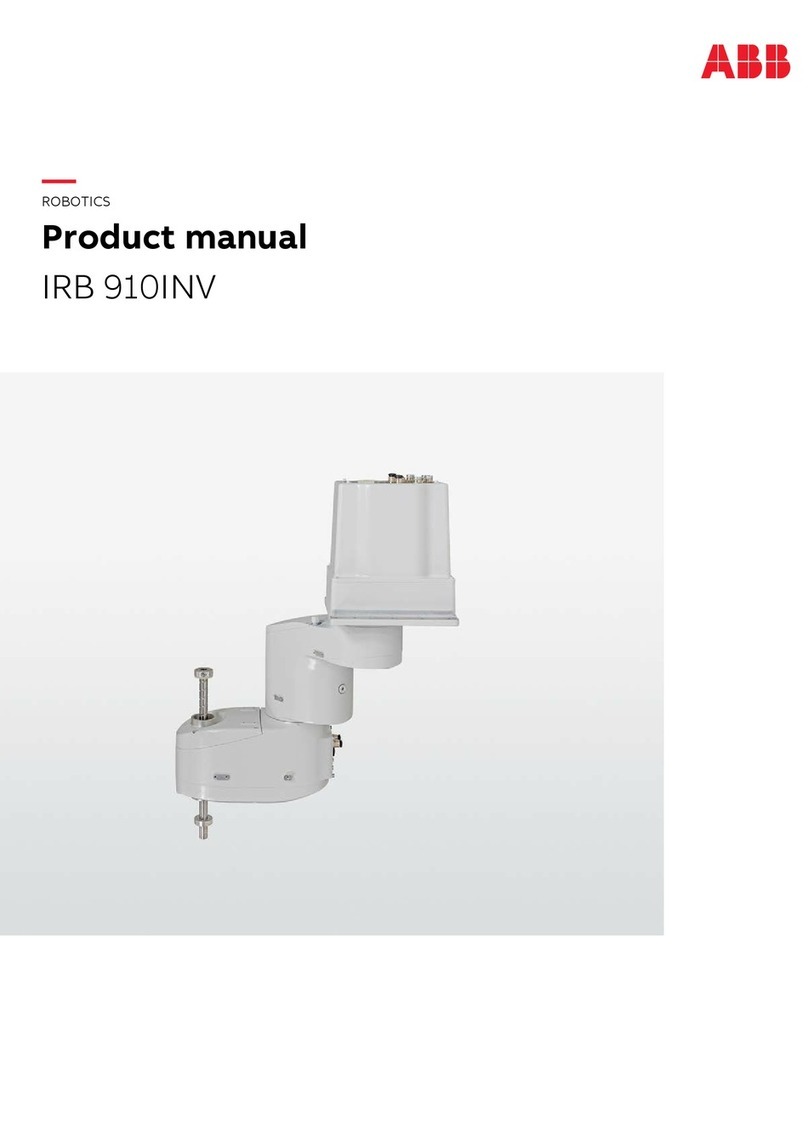
ABB IRB 910INV Owner's manual

ROBOTICS
Product specification
IRB 910INV

Trace back information:
Workspace 23C version a7
Checked in 2023-09-21
Skribenta version 5.5.019

Product specification
IRB 910INV-3/0.35
IRB 910INV-6/0.55
OmniCore
Document ID: 3HAC068057-001
Revision: M
© Copyright 2019-2023 ABB. All rights reserved.
Specifications subject to change without notice.

The information in this manual is subject to change without notice and should not
be construed as a commitment by ABB. ABB assumes no responsibility for any errors
that may appear in this manual.
Except as may be expressly stated anywhere in this manual, nothing herein shall be
construed as any kind of guarantee or warranty by ABB for losses, damage to persons
or property, fitness for a specific purpose or the like.
In no event shall ABB be liable for incidental or consequential damages arising from
use of this manual and products described herein.
This manual and parts thereof must not be reproduced or copied without ABB's
written permission.
Keep for future reference.
Additional copies of this manual may be obtained from ABB.
Original instructions.
© Copyright 2019-2023 ABB. All rights reserved.
Specifications subject to change without notice.

Table of contents
7Overview of this manual ...................................................................................................................
91 Description
91.1 Structure ......................................................................................................... 91.1.1 Introduction to structure ........................................................................... 121.1.2 The robot ............................................................................................... 131.1.2.1 Technical data ............................................................................ 191.2 Standards ........................................................................................................ 191.2.1 Applicable standards ............................................................................... 201.3 Installation ....................................................................................................... 201.3.1 Introduction to installation ......................................................................... 211.3.2 Operating requirements ............................................................................ 221.3.3 Mounting the manipulator ......................................................................... 241.4 Load diagrams .................................................................................................. 241.4.1 Introduction to load diagram ...................................................................... 251.4.2 Load diagram ......................................................................................... 271.4.3 Maximum load and moment of inertia .......................................................... 281.4.4 Maximum TCP acceleration ....................................................................... 291.5 Mounting of equipment ....................................................................................... 341.6 Calibration ....................................................................................................... 341.6.1 Calibration methods ................................................................................. 361.6.2 Fine calibration ....................................................................................... 371.6.3 Absolute Accuracy option ......................................................................... 391.7 Maintenance and troubleshooting ......................................................................... 391.7.1 Introduction to maintenance and trouble shooting ......................................... 401.8 Robot motion .................................................................................................... 411.8.1 Working range and type of motion .............................................................. 431.8.2 Performance according to ISO 9283 ............................................................ 441.8.3 Velocity ................................................................................................. 451.9 Robot stopping distances and times ..................................................................... 451.9.1 Robot stopping distances according to ISO 10218-1 ...................................... 491.9.2 Measuring stopping distance and time ........................................................ 511.9.3 IRB 910INV-3/0.35 ................................................................................... 571.9.4 IRB 910INV-3/0.35 IP54/CR ....................................................................... 631.9.5 IRB 910INV-6/0.55 ................................................................................... 691.9.6 IRB 910INV-6/0.55 IP54/CR ....................................................................... 751.10 Customer connections .......................................................................................
772 Specification of variants and options
772.1 Introduction to variants and options ...................................................................... 782.2 Manipulator ...................................................................................................... 812.3 Floor cables ..................................................................................................... 842.4 User documentation ..........................................................................................
853 Accessories
87Index
Product specification - IRB 910INV 5
3HAC068057-001 Revision: M
© Copyright 2019-2023 ABB. All rights reserved.
Table of contents

This page is intentionally left blank

Overview of this manual
About this product specification
This product specification describes the performance of the manipulator or a
complete family of manipulators in terms of:
• The structure and dimensional prints
• The fulfilment of standards, safety, and operating equipment
• The load diagrams, mounting or extra equipment, the motion, and the robot
reach
• The specification of available variants and options
The specification covers the manipulator using the OmniCore controller.
Usage
Product specifications are used to find data and performance about the product,
for example to decide which product to buy. How to handle the product is described
in the product manual.
The specification is intended for:
• Product managers and product personnel
• Sales and marketing personnel
• Order and customer service personnel
References
Document IDDocument name
3HAC065034-001Product specification - OmniCore C line
3HAC079823-001Product specification - OmniCore E line
3HAC060860-001Product manual - OmniCore C30
3HAC073706-001Product manual - OmniCore C90XT
3HAC079399-001Product manual - OmniCore E10
3HAC068055-001Product manual - IRB 910INV
Revisions
DescriptionRevision
First edition.A
Published in release R19D The following updates are done in this revi-
sion:
• Protection option 3350-540 Base 54 and 3351-1 Cleanroom 1 ad-
ded. 209-2 ABB white standard added.
• Minor changes.
B
Published in release R20C. The following updates are done in this revi-
sion:
• Minor Changes.
• Absacc production data added.
C
Continues on next page
Product specification - IRB 910INV 7
3HAC068057-001 Revision: M
© Copyright 2019-2023 ABB. All rights reserved.
Overview of this manual

DescriptionRevision
Published in release R20D. The following updates are done in this revi-
sion:
• Minor Changes.
• Warranty section updated.
D
Published in release R21A. The following updates are done in this revi-
sion:
• Maximum TCP acceleration added.
• Connector types for CP/CS and Ethernet floor cable wiring are
added.
E
Published in release R21B. The following updates are done in this revi-
sion:
• Performance data according to ISO 9283 updated.
• Modified the air hose diameter description.
• Text regarding fastener quality is updated.
• Added a note to remind users that mechanical stop locations
cannot be adjusted.
• Removed Axis resolution.
• Added a note in manipulator protection chapter.
F
Published in release R21C. The following updates are done in this revi-
sion:
• Removed option 438-4/5/7.
• Option 3209-1 added.
G
Published in release R21D. The following updates are done in this revi-
sion:
• Supported controller OmniCore E10 is added.
H
Published in release R22A. The following updates are done in this revi-
sion:
•Added screwing depth information to attachment screws for robot
foundation.
J
Published in release R22D. The following updates are done in this revi-
sion:
• Updated power consumption data.
• Added Mains cable [3203-x].
K
Published in release R23B. The following updates are done in this revi-
sion:
• Added table for Max down force (Z stroke).
L
Published in release 23C. The following updates are done in this revision:
• The updated robot stopping distances and times are moved to
this document, and removed from the generic document, see
Robot stopping distances and times on page 45.
M
8 Product specification - IRB 910INV
3HAC068057-001 Revision: M
© Copyright 2019-2023 ABB. All rights reserved.
Overview of this manual
Continued
1 Description
1.1 Structure
1.1.1 Introduction to structure
General
The IRB 910INV is ABB Robotics second generation SCARA robot, with 4 axes
and a max payload of 3 kg and 6 kg in two different reach variants 0.35 m and 0.55
m, designed specifically for manufacturing industries that use flexible robot-based
automation, e.g. 3C industry. The robot has an open structure that is especially
adapted for flexible use, and can communicate extensively with external systems.
Clean room robots
xx2000001471
Particle emission from the robot fulfill Clean room class 1 standard according to
DIN EN ISO 14644-1.
Clean room robots are specially designed to work in a clean room environment.
According to IPA test result:
The robot IRB 910INV is suitable for use in clean rooms fulfilling the Air Cleanliness
Class 1 according to ISO 14644-1, when operated at a capacity of 50%.
The robot IRB 910INV is suitable for use in clean rooms fulfilling the Air Cleanliness
Class 1 according to ISO 14644-1, when operated at a capacity of 100%.
Clean room robots are designed in order to prevent from particle emission from
the robot. For example is, frequent maintenance work possible to perform without
cracking the paint. The robot is painted with four layers of polyurethane paint. The
last layer being a varnish over labels in order to simplify cleaning. The paint has
been tested regarding outgassing of Volatile Organic Compounds (VOC) and been
classified in accordance with ISO 14644-8.
Continues on next page
Product specification - IRB 910INV 9
3HAC068057-001 Revision: M
© Copyright 2019-2023 ABB. All rights reserved.
1 Description
1.1.1 Introduction to structure

Classification of airborne molecular contamination, see below:
Outgassing amountParameter
Classifica-
tion in ac-
cordance to
ISO 14644-
8
Normed
based on
1m2and
1s(g)
Total detec-
ted (ng)
Performed
test
Temp (°C)Test dura-
tion (s)
Area (m2)
-6.81.7E-072848TVOC2336004.5E-03
-3.81.7E-0446524TVOC90604.5E-03
Classification results in accordance with ISO 14644-8 at different test temperatures.
IP54 protection
The robot has IP54 as an option. The option will add sealing, machining parts and
gaskets.
Operating system
The robot is equipped with the OmniCore C30/C90/E10 controller and robot control
software, RobotWare. RobotWare supports every aspect of the robot system, such
as motion control, development and execution of application programs,
communication etc. See Operating manual - OmniCore.
Safety
The safety standards are valid for the complete robot, manipulator and controller.
Additional functionality
For additional functionality, the robot can be equipped with optional software for
application support - for example dispensing and cutting, communication features
- network communication - and advanced functions such as multitasking, sensor
control etc. For a complete description on optional software, see the Product
specification - OmniCore C line and Product specification - OmniCore E line.
Continues on next page
10 Product specification - IRB 910INV
3HAC068057-001 Revision: M
© Copyright 2019-2023 ABB. All rights reserved.
1 Description
1.1.1 Introduction to structure
Continued

Manipulator axes
xx1900000084
DescriptionPosi-
tion
DescriptionPosi-
tion
Axis 22Axis 11
Axis 44Axis 33
Product specification - IRB 910INV 11
3HAC068057-001 Revision: M
© Copyright 2019-2023 ABB. All rights reserved.
1 Description
1.1.1 Introduction to structure
Continued

1.1.2 The robot
General
The IRB 910INV is available in two variants and both can only be mounted on
ceiling, no other mounting position is permitted.
Reach (m)Maximum handling capacity
(kg)
Robot type
0.35 m3 kgIRB 910INV-3/0.35
0.55 m6 kgIRB 910INV-6/0.55
Continues on next page
12 Product specification - IRB 910INV
3HAC068057-001 Revision: M
© Copyright 2019-2023 ABB. All rights reserved.
1 Description
1.1.2 The robot

1.1.2.1 Technical data
Weight, robot
The table shows the weight of the robot.
Nominal weightRobot model
IRB 910INV-3/0.35: 19 kgIRB 910INV
IRB 910INV-6/0.55: 22 kg
Note
The weight does not include additional options, tools and other equipment fitted
on the robot.
Mounting positions
The table shows valid mounting positions and the installation (mounting) angle for
the manipulator.
Installation angleMounting position
0° i
Inverted
iA tilt of up to 3° does not affect the payload or reach, but it can have a negative impact on
performance and lifetime. The actual value must be set in the system parameters.
Note
The actual mounting angle must always be configured in the system parameters,
otherwise the performance and lifetime is affected. See the product manual for
details.
Loads on foundation, robot
The illustration shows the directions of the robots stress forces.
The directions are valid for all inverted robots.
Tz
Fz
Txy
Fxy
xx1900000059
Continues on next page
Product specification - IRB 910INV 13
3HAC068057-001 Revision: M
© Copyright 2019-2023 ABB. All rights reserved.
1 Description
1.1.2.1 Technical data

Force in any direction in the XY planeFxy
Force in the Z planeFz
Bending torque in any direction in the XY planeTxy
Bending torque in the Z planeTz
The table shows the various forces and torques working on the robot during different
kinds of operation.
Note
These forces and torques are extreme values that are rarely encountered during
operation. The values also never reach their maximum at the same time!
WARNING
The robot installation is restricted to the mounting options given in following load
table(s).
Inverted
Max. load (emergency stop)Endurance load (in operation)Force
±770/710 N±420/440 NForce xy
190 ±660/220 ±110 N190 ±135/220 ±200 NForce z
±220/320 Nm±220/170 NmTorque xy
±160/190Nm±90/125 NmTorque z
Requirements, foundation
The table shows the requirements for the foundation where the weight of the
installed robot is included:
NoteValueRequirement
Flat foundations give better repeatability of
the resolver calibration compared to original
settings on delivery from ABB.
0.1/500 mmFlatness of foundation
surface
The value for levelness aims at the circum-
stance of the anchoring points in the robot
base.
In order to compensate for an uneven sur-
face, the robot can be recalibrated during in-
stallation. If resolver/encoder calibration is
changed this will influence the absolute ac-
curacy.
The value is recommended for optimal per-
formance.
22 Hz
Note
It may affect the ma-
nipulator lifetime to
have a lower reson-
ance frequency than
recommended.
Minimum resonance
frequency
Due to foundation stiffness, consider robot
mass including equipment.i
For information about compensating for
foundation flexibility, see the description of
Motion Process Mode in the manual that de-
scribes the controller software option, see
References on page 7.
Continues on next page
14 Product specification - IRB 910INV
3HAC068057-001 Revision: M
© Copyright 2019-2023 ABB. All rights reserved.
1 Description
1.1.2.1 Technical data
Continued

NoteValueRequirement
150 MPaMinimum foundation
material yield strength
iThe minimum resonance frequency given should be interpreted as the frequency of the robot
mass/inertia, robot assumed stiff, when a foundation translational/torsional elasticity is added, i.e.,
the stiffness of the pedestal where the robot is mounted. The minimum resonance frequency should
not be interpreted as the resonance frequency of the building, floor etc. For example, if the equivalent
mass of the floor is very high, it will not affect robot movement, even if the frequency is well below
the stated frequency. The robot should be mounted as rigid as possibly to the floor.
Disturbances from other machinery will affect the robot and the tool accuracy. The robot has
resonance frequencies in the region 10 – 20 Hz and disturbances in this region will be amplified,
although somewhat damped by the servo control. This might be a problem, depending on the
requirements from the applications. If this is a problem, the robot needs to be isolated from the
environment.
Storage conditions, robot
The table shows the allowed storage conditions for the robot:
ValueParameter
-25°CMinimum ambient temperature
55°CMaximum ambient temperature
70°CMaximum ambient temperature (less than 24 hrs)
95% at constant temperature
(gaseous only)
Maximum ambient humidity
Operating conditions, robot
The table shows the allowed operating conditions for the robot:
ValueParameter
5°C i
Minimum ambient temperature
45°CMaximum ambient temperature
95% at constant temperatureMaximum ambient humidity
iAt low environmental temperature < 10ºC is, as with any other machine, a warm-up phase
recommended to be run with the robot. Otherwise there is a risk that the robot stops or run with
lower performance due to temperature dependent oil and grease viscosity.
Protection classes, robot
The table shows the available protection types of the robot, with the corresponding
protection class.
Protection class i
Protection type
IP30ii
Manipulator, protection type Standard
IP54 (option 3350-540)
ISO Class 1Manipulator, protection type Clean Room
iAccording to IEC 60529.
ii The protection class of the ballscrew area is IP20. For more information, please contact ABB.
Environmental information
The product complies with IEC 63000. Technical documentation for the assessment
of electrical and electronic products with respect to the restriction of hazardous
substances.
Continues on next page
Product specification - IRB 910INV 15
3HAC068057-001 Revision: M
© Copyright 2019-2023 ABB. All rights reserved.
1 Description
1.1.2.1 Technical data
Continued

Other technical data
NoteDescriptionData
< 70 dB (A) Leq (acc. to the work-
ing space Machinery directive
2006/42/EC)
The sound pressure level outsideAirborne noise level
Power consumption with OmniCore C30/90XT
IRB 910INV-6/0.55IRB 910INV-3/0.35Robot in 0 degree position
8174Brakes engaged (W)
115102Brakes disengaged (W)
Power consumption with OmniCore E10
IRB 910INV-6/0.55IRB 910INV-3/0.35Robot in 0 degree position
5858Brakes engaged (W)
10191Brakes disengaged (W)
16 Product specification - IRB 910INV
3HAC068057-001 Revision: M
© Copyright 2019-2023 ABB. All rights reserved.
1 Description
1.1.2.1 Technical data
Continued

Dimensions of IRB 910INV-3/0.35
Robots with protection class IP30
53
16 h7
30
0
424
213
104
0
175
22.5
228
255
200
180
134
0
35
53
123
135
65
xx1800002818
Robots with protection class IP54 or with protection type Clean Room
53
16 h7
30
0
458
213
101.5
0
175
22.5
228
255
200
180
134
0
35
53
123
135
65
xx1900001540
Product specification - IRB 910INV 17
3HAC068057-001 Revision: M
© Copyright 2019-2023 ABB. All rights reserved.
1 Description
1.1.2.1 Technical data
Continued

Dimensions of IRB 910INV-6/0.55
Robots with protection class IP30
58
30
20
h7
0
22.5
104
281
504
213
0
275
355
200
180
134
0
35
123
135
53
65
xx1900000217
Robots with protection class IP54 or with protection type Clean Room
The figure shows the dimension of the IRB 910INV-6/0.55 for Clean Room/IP54.
58
30
0
22.5
101.5
281
543
213
0
275
355
200
180
134
0
35
123
135
53
65
20
h7
xx1900001541
18 Product specification - IRB 910INV
3HAC068057-001 Revision: M
© Copyright 2019-2023 ABB. All rights reserved.
1 Description
1.1.2.1 Technical data
Continued

1.2 Standards
1.2.1 Applicable standards
General
The product is compliant with ISO 10218-1:2011, Robots for industrial environments
- Safety requirements - Part 1 Robots, and applicable parts in the normative
references, as referred to from ISO 10218-1:2011. In case of deviation from ISO
10218-1:2011, these are listed in the declaration of incorporation. The declaration
of incorporation is part of the delivery.
Robot standards
DescriptionStandard
Manipulating industrial robots – Performance criteria and re-
lated test methods
ISO 9283
Robots and robotic devices – Coordinate systems and motion
nomenclatures
ISO 9787
Manipulating industrial robots – Presentation of characteristicsISO 9946
Other standards used in design
DescriptionStandard
Safety of machinery - Electrical equipment of machines - Part
1: General requirements, normative reference from ISO 10218-
1
IEC 60204-1
Electromagnetic compatibility (EMC) – Part 6-2: Generic
standards – Immunity standard for industrial environments
IEC 61000-6-2
Electromagnetic compatibility (EMC) – Part 6-4: Generic
standards – Emission standard for industrial environments
IEC 61000-6-4
Safety of machinery - Safety related parts of control systems
- Part 1: General principles for design, normative reference
from ISO 10218-1
ISO 13849-1:2006
Protection of electronic devices from electrostatic phenomena
- General requirements
IEC 61340-5-1
Region specific standards and regulations
DescriptionStandard
Safety requirements for industrial robots and robot systemsANSI/RIA R15.06
Safety standard for robots and robotic equipmentANSI/UL 1740
Industrial robots and robot Systems - General safety require-
ments
CAN/CSA Z 434-03
Protection of Electrical and Electronic Parts, Assemblies and
Equipment (Excluding Electrically Initiated Explosive Devices)
ANSI/ESD S20.20
Robots and robotic devices — Safety requirements for indus-
trial robots — Part 1: Robots
EN ISO 10218-1
Product specification - IRB 910INV 19
3HAC068057-001 Revision: M
© Copyright 2019-2023 ABB. All rights reserved.
1 Description
1.2.1 Applicable standards

1.3 Installation
1.3.1 Introduction to installation
General
IRB 910INV is available in two variants and all variants can only be
inverted/suspended. Depending on the robot variant, an end effector with max.
weight of 3 kg or 6 kg, including payload, can be mounted on the lower end of the
ball screw spline shaft (axis 4). See Load diagram on page 25.
20 Product specification - IRB 910INV
3HAC068057-001 Revision: M
© Copyright 2019-2023 ABB. All rights reserved.
1 Description
1.3.1 Introduction to installation
Other manuals for IRB 910INV
1
Table of contents
Other ABB Robotics manuals

ABB
ABB IRB 120 User manual

ABB
ABB M2004 User instructions

ABB
ABB IRB 14000 User manual

ABB
ABB IRB 6600 - 225/2.55 type B User manual

ABB
ABB IRB 760 Series User manual

ABB
ABB IRB 260 User manual

ABB
ABB IRC5 with FlexPendant User manual

ABB
ABB IRC5 Compact User guide

ABB
ABB IRB 6620 Guide

ABB
ABB IRB 4400 User manual

ABB
ABB IRB 2400/10 Owner's manual

ABB
ABB IRB 6620 User manual

ABB
ABB OmniCore IRB 6740 User manual

ABB
ABB IRB 6730 User manual

ABB
ABB Feather Duster User manual

ABB
ABB CRB 1100 User manual

ABB
ABB IRB 6620LX User manual

ABB
ABB OmniCore User manual

ABB
ABB IRB 8700 Owner's manual

ABB
ABB IRB 8700 Series User manual