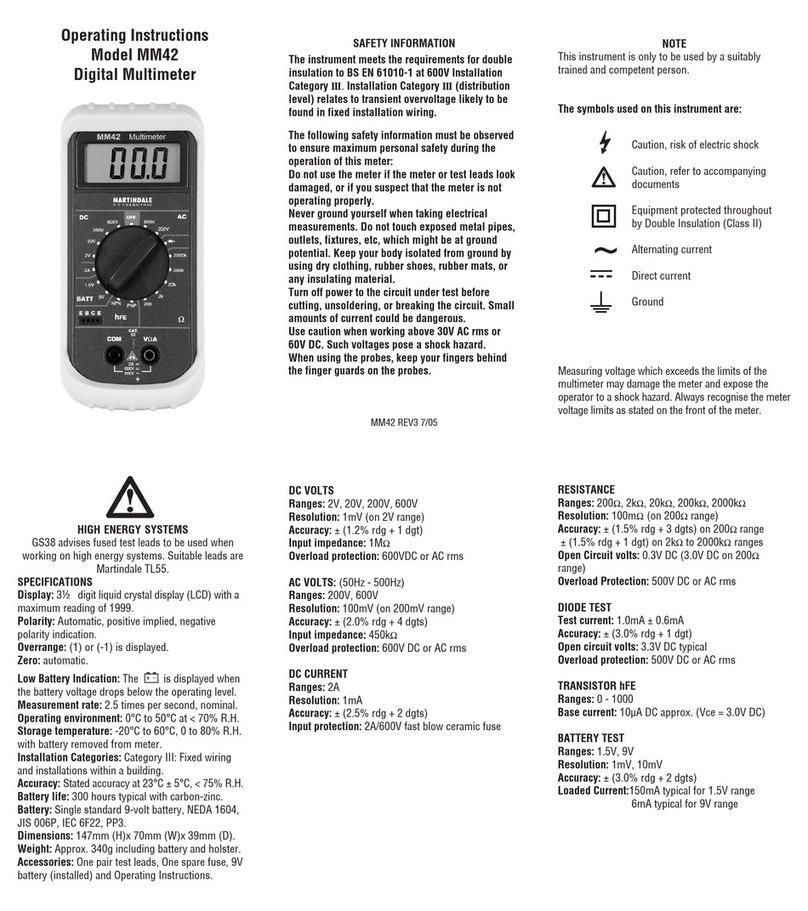
bauhaus 2148888B User manual

Users Manual
Read this manual thoroughly before use
Digital Multimeter

2
SAFETY INFORMATION
This meter has been designed according to IEC 61010
concerning electronic measuring instruments with a
measurement category ( CAT III 300V ) and pollution
degree 2.
To avoid possible electric shock or personal injury,
Warning
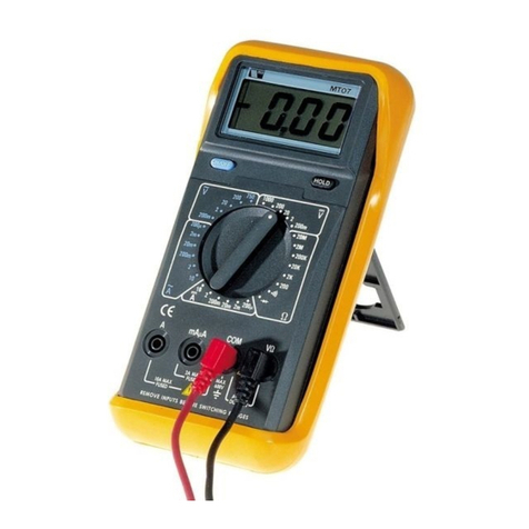
This meter is a compact 3 ½ digit, digital multimeter,
designed to measure DC and AC voltage, DC and AC
current, resistance, diode, continuity and battery.
Some models also have temperature measurement
function, frequency measurement function, non-contact AC
voltage detection function, or live ac wire detection function
This multimeter features backlight, data hold, full-range
overload protection, illumination function, etc
It is an easy to operate, useful testing tool.
INTRODUCTION

3
follow
these guidelines:
Do not use the meter if it is damaged. Before you use
the meter, inspect the case. Pay particular attention to
the insulation surrounding the connectors.
Inspect the test leads for damaged insulation or
exposed metal. Check the test leads for continuity.
Replace damaged test leads before you use the meter.
Do not use the meter if it operates abnormally.
Protection may be impaired. When in doubt, have the
meter serviced.
Do not operate the meter where explosive gas, vapor,
or dust is present.
Do not apply more than the rated voltage, as marked
on the meter, between terminals or between any
terminal and earth ground.
Before use, verify the meter's operation by measuring a
known voltage.
When measuring current, turn off circuit power before
connecting the meter in the circuit. Remember to place
the meter in series with the circuit.
When servicing the meter, use only specified
replacement parts.
Use caution when working with voltage above 30V AC
rms, 42V peak, or 60V DC. Such voltages pose a shock
hazard.

4
When using the probes, keep your fingers behind the
finger guards on the probes.
Connect the common test lead before you connect the
live test lead. When you disconnect test leads,
disconnect the live test lead first.
Remove the test leads from the meter before you open
the battery cover or the case.
Do not operate the meter with the battery cover or
portions of the case removed or loosened.
To avoid false readings, which could lead to possible
electric shock or personal injury, replace the battery
as soon as the low battery indicator ( ) appears.
Do not use the meter in a manner not specified by this
manual or the safety features provided by the meter
may be impaired.
Adhere to local and national safety codes. Individual
protective equipment must be used to prevent shock
and arc blast injury where hazardous live conductors
are exposed.
To void electric shock and personal injury, do not touch
any naked conductor with hand or skin; and do not
ground yourself while using this meter.
Do not use the meter if the meter, a test lead or your
hand is wet.

Caution
To avoid possible damage to the meter or to the
equipment under test, follow these guidelines:
Disconnect circuit power and discharge all capacitors
thoroughly before testing resistance, diode, continuity
or temperature.
Use the proper terminals, function and range for your
measurements.
5
Remaining endangerment:
When an input terminal is connected to dangerous live
potential it is to be noted that this potential can occur
at all other terminals!
CATIII - Measurement Category III is for
measurements performed in the building installation.
Examples are measurements on distribution boards,
circuit breakers, wiring, including cables, bus-bars,
junction boxes, switches, socket-outlets in the fixed
installation, and equipment for industrial use and some
other equipment, for example, stationary motors with
permanent connection to the fixed installation.
Do not use the meter for measurements within
Measurement Categories IV.

6
Electrical Symbols
Alternating Current
Direct Current
Both direct and alternating current
Caution, risk of danger, refer to the operating manual
before use.
Caution, risk of electric shock.
Earth (ground) Terminal
Fuse
Conforms to European Union directives
The equipment is protected throughout by double
insulation or reinforced insulation.
Before measuring current, check the meter's fuses and
turn off power to the circuit before connecting the
meter to the circuit.
Before turning the rotary switch to change functions,
disconnect the test leads from the circuit under test.

7
FRONT PANEL
1. Display
3 1/2-digit LCD, with a max. reading of 1999
2. " AC/DC " Button
Used to switch between DC and AC functions.
3. AC Voltage Detection Button
12
310
11
13
49
1
2
5
6 7 8

4. Backlight Button
Press this button to turn on or off the backlight. The
backlight will turn off automatically about 30 secs later
after it is turned on.
5. Function/Range Switch
Used to select desired function or range as well as to
turn on or off the meter.
To preserve battery life, set this function/range switch
in the " OFF " position when the meter is not in use.
6. " 10A " Terminal
Plug-in connector for the red test lead for current
( 200mA - 10A ) measurements.
7. " COM " Terminal
This terminal is a plug-in connector for the black test
lead. It is also a plug-in connector for the negative (
-
)
plug of the K type thermocouple for temperature
measurements.
8. " VmA " Terminal
This terminal is a plug-in connector for the red test lead
for all measurements except temperature measurements
and the current measurements 200mA. It is also a
plug-in connector for the positive (+) plug of the
K type
thermocouple for temperature measurements.
8

9
9. Illumination Button
Press and hold down this button to turn on the
illumination lamp. To turn off the illumination lamp, just
release this button.
10. AC Voltage Detection Indicator
11. " H " Button
Used to enter/exit Data Hold mode.
12. Holster
13. Illumination Lamp
GENERAL SPECIFICATION
Display: 3 1/2-digit LCD, with a max. reading of 1999
Negative Polarity Indication: Negative sign "
-
" shown
on the display automatically
Sampling Rate: About 2 - 3 times/sec
IP Degree: IP20
Battery: 9V battery, 6F22 or equivalent, 1 pieces
Low Battery Indication: " " shown on the display
Operating Environment: Temperature: 0°C to 40°C
Relative Humidity: < 75%

10
SPECIFICATIONS
Accuracy is specified for a period of one year after
calibration and at 18°C to 28°C, with relative humidity
< 75%.
Accuracy specifications take the form of:
±([% of Reading] + [number of Least Significant Digits])
ResolutionRange Accuracy
200mV
2V
20V
200V
300V
± (0.8% + 5)
100µV
1mV
10mV
100mV
1V ± (1.0% + 5)
DC Voltage
± (0.5% + 5)
Overrange
Indication
"OL" shown
on the display
Storage Environment: Temperature: -10°C to 50°C
Relative Humidity: < 85%
Size: 170×86×40mm
Weight: About 290g ( including battery )

11
DC Current
AC Voltage
200mV
2V
20V
200V
300V
100µV
1mV
10mV
100mV
1V
± (1.2% + 5)
Frequency Range: 40Hz - 400Hz
Response: Average, calibrated in rms of sine wave
Max. Allowable Input voltage: 300V AC rms
ResolutionRange Accuracy
± (1.0% + 5)
Overrange
Indication
"OL" shown
on the display
± (1.5% + 5)
± (2.0% + 5)
± (1.0% + 5)
1
Input Impedance: 10M
Max. Allowable Input Voltage: 300V DC
2mA
20mA
200mA
10A
1µA
10µA
100µA
10mA
ResolutionRange Accuracy Overrange
Indication
"OL" shown
on the display

Overload Protection:
250mA/300V FAST Fuse ( for " VmA "terminal inputs )
10A/300V FAST Fuse ( for "10A " terminal inputs )
Max. Allowable Input Current: 10A
( For inputs > 2A: measurement duration < 10 secs, and
interval > 15 minutes )
Overload Protection:
250mA/300V FAST Fuse ( for " VmA "terminal inputs )
10A/300V FAST Fuse ( for " 10A " terminal inputs )
Max. Allowable Input Current: 10A
( For inputs > 2A: measurement duration < 10 secs, and
interval > 15 minutes )
AC Current
12
± (1.8% + 5)
± (3.0% + 5)
± (1.3% + 5)
1
2mA
20mA
200mA
10A
1µA
10µA
100µA
10mA
ResolutionRange Accuracy Overrange
Indication
"OL" shown
on the display

13
Resistance
Max. Open Circuit Voltage: About 2.8V
200
2k
20k
200k
2M 1k
100
1
10
0.1
± (1.2% + 5)
20M 10k ± (1.5% + 7)
ResolutionRange Accuracy Overrange
Indication
"OL" shown
on the display
Frequency Range: 40Hz - 400Hz
Response: Average, calibrated in rms of sine wave

Battery Test
1.5V
Range
9V
12V
The working voltage of the
battery will be shown on the
display so that the quality of
the battery can be judged.
about 20mA
Description Test Current
about 5mA
about 4mA
14
Temperature
1 If the temperature being measured is out of the range
of 0°C to 1000°C ,the display may show a reading;
but the measurement error
may be large or the
thermocouple may be damaged.
Note:
1. Use K type thermocouple.
2.
Accuracy does not include error of the thermocouple
probe.
3. Accuracy specification assumes ambient temperature
is stable to ±1°C ( or ±1.8°F ). For ambient temperature
± (1.0% + 5)
± (2.5% + 10)
Reso-
lution
Range Accuracy Overrange
Indication
0°C
-
400°C
400°C
-
1000°C 1°C
Model

15
Test Condition
Diode and Continuity Test
Range Description
Open Circuit Voltage:
about 2.8V
Test Current:
about 1mA
The approx. forward voltage
drop of the diode will be
displayed.
changes of ±5°C ( or ±9°F ), rated accuracy applies
after 1 hour.

OPERATING INSTRUCTION
Data Hold Mode
Press the " H" button to hold the present reading on the
display. " " appears on the display as an indicator.
To exit the Data Hold mode, press the button again. " "
disappears.
Measuring DC or AC Voltage
1. Connect the black test lead to the "COM" terminal and
the red test lead to the " VmA" terminal.
2. Set the range switch to desired range position.
If the magnitude of the voltage to be measured is not
known beforehand, set the range switch to the highest
16

Measuring DC or AC Current
1. Connect the black test lead to the " COM " terminal.
Connect the red test lead to the " VmA " terminal if the
current to be measured is less than 200mA. If the
current is between 200mA and 10A, connect the red
test lead to the " 10A " terminal instead.
2. Set the range switch to desired range position.
3.
Select dc or ac current measurement with the " AC/DC "
button according to the marks beside this button.
17
range first and then reduce it range by range until
satisfactory resolution is obtained.
3.
Select DC or AC voltage measurement with the " AC/DC
"
button according to the marks beside this button.
4. Connect the test leads across the source or circuit to be
tested.
5. Read the reading on the display. For DC
voltage measurements, the polarity of the red
test lead connection will be indicated as well.
Note:
To avoid electric shock to you or damages to the meter, do
not apply a voltage higher than 300V between the
terminals.

18
4.
Turn off power to the circuit to be tested. Then discharge
all high-voltage capacitors.
5. Break the circuit path to be
tested
, then connect the test
leads in series with the circuit.
6. Turn on power to the circuit, then read the reading on the
display. For DC current measurements, the polarity of
the red test lead connection will be indicated as well.
Note:
1. If the magnitude of the current to be measured is not
known beforehand, set the range switch to the highest
range first and then reduce it range by range until
satisfactory resolution is obtained.
2.If the red test lead is connected to the " 10A " terminal,
the range switch must be set in the 10A range position.
If the range switch is set in the 10A range position, the
red test lead must be connected to the " 10A " terminal.
Measuring Resistance
1. Connect the black test lead to the " COM " terminal and
the red test lead to the " VmA " terminal.
2. Set the range switch to desired range position.
3. Connect the test leads across the object to be tested.
4. Read the reading on the display.

19
Note:
1. For measurements > 1M , the meter may take a few
seconds to stabilize reading. This is normal for high
resistance measurements.
2. When the input is not connected, i.e. at open circuit,
" OL " will be displayed as an overrange indication.
3. Before test, disconnect all power to the circuit to be
tested and discharge all capacitors thoroughly.
Diode Test
1. Connect the black test lead to the " COM " terminal and
the red test lead to the " VmA " terminal. ( Note: The
polarity of the red lead is positive " + ". )
2. Set the range switch to position.
3.
Connect the red test lead to the anode of the diode to
be tested and the black test lead to the cathode of the
diode.
4. The display shows the approximate forward voltage
drop of the diode. If the connection is reversed, "OL"
will be shown on the display.
Note:
Before test, disconnect all power to the circuit to be tested
and discharge all capacitors thoroughly.

20
Continuity Test
1. Connect the black test lead to the " COM " terminal and
the red test lead to the " VmA " terminal.
2. Set the range switch to position.
4. Connect the test leads across the circuit to be tested.
5. If the resistance is less than about 20 , the buzzer
will sound.
Note:
Before test, disconnect all power to the circuit to be tested
and discharge all capacitors thoroughly.
Battery Test
1. Connect the black test lead to the " COM " terminal and
the red test lead to the " VmA " terminal.
2. According to the rated voltage of the battery to b
e tested,
set the range switch to the corresponding BATT. range
Table of contents
Other bauhaus Multimeter manuals

