Doc. I317IGB12_19.doc 18/12/2019 P. 8 / 41
Algoritmo di calcolo del CRC
CRC calculation algorithm
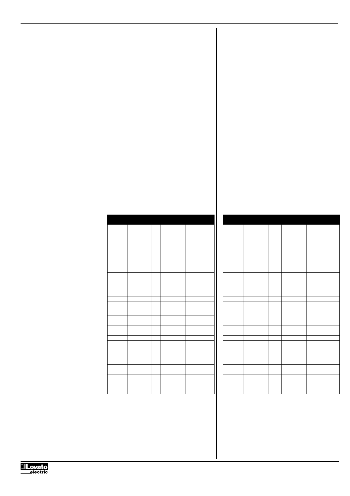
CALCOLO DEL CRC (CHECKSUM per RTU)
Esempio di calcolo:
Frame = 0207h
Inizializzazione CRC 1111 1111 1111 1111
Carica primo byte 0000 0010
Esegue xor con il primo 1111 1111 1111 1101
Byte della frame
Esegue primo shift a dx 0111 1111 1111 1110 1
Carry=1,carica polinomio 1010 0000 0000 0001
Esegue xor con il 1101 1111 1111 1111
polinomio
Esegue secondo shift dx 0110 1111 1111 1111 1
Carry=1,carica polinomio 1010 0000 0000 0001
Esegue xor con il 1100 1111 1111 1110
polinomio
Esegue terzo shift 0110 0111 1111 1111 0
Esegue quarto shift 0011 0011 1111 1111 1
Carry=1, carica polinomio 1010 0000 0000 0001
Esegue xor con il 1001 0011 1111 1110
Polinomio
Esegue quinto shift dx 0100 1001 1111 1111 0
Esegue sesto shift dx 0010 0100 1111 1111 1
Carry=1, carica polinomio 1010 0000 0000 0001
Esegue xor con polinomio 1000 0100 1111 1110
Esegue settimo shift dx 0100 0010 0111 1111 0
Esegue ottavo shift dx 0010 0001 0011 1111 1
Carry=1, carica polinomio 1010 0000 0000 0001
Carica secondo byte 0000 0111
della frame
Esegue xor con il 1000 0001 0011 1001
Secondo byte della frame
Esegue primo shift dx 0100 0000 1001 1100 1
Carry=1, carica polinomio 1010 0000 0000 0001
Esegue xor con il 1110 0000 1001 1101
polinomio
Esegue secondo shift dx 0111 0000 0100 1110 1
Carry=1, carica polinomio 1010 0000 0000 0001
Esegue xor con il 1101 0000 0100 1111
polinomio
Esegue terzo shift dx 0110 1000 0010 0111 1
Carry=1, carica polinomio 1010 0000 0000 0001
Esegue xor con il 1100 1000 0010 0110
polinomio
Esegue quarto shift dx 0110 0100 0001 0011 0
Esegue quinto shift dx 0010 0100 0000 1001 1
Carry=1, carica polinomio 1010 0000 0000 0001
Esegue xor con il 1001 0010 0000 1000
polinomio
Esegue sesto shift dx 0100 1001 0000 0100 0
Esegue settimo shift dx 0010 0100 1000 0010 0
Esegue ottavo shift dx 0001 0010 0100 0001 0
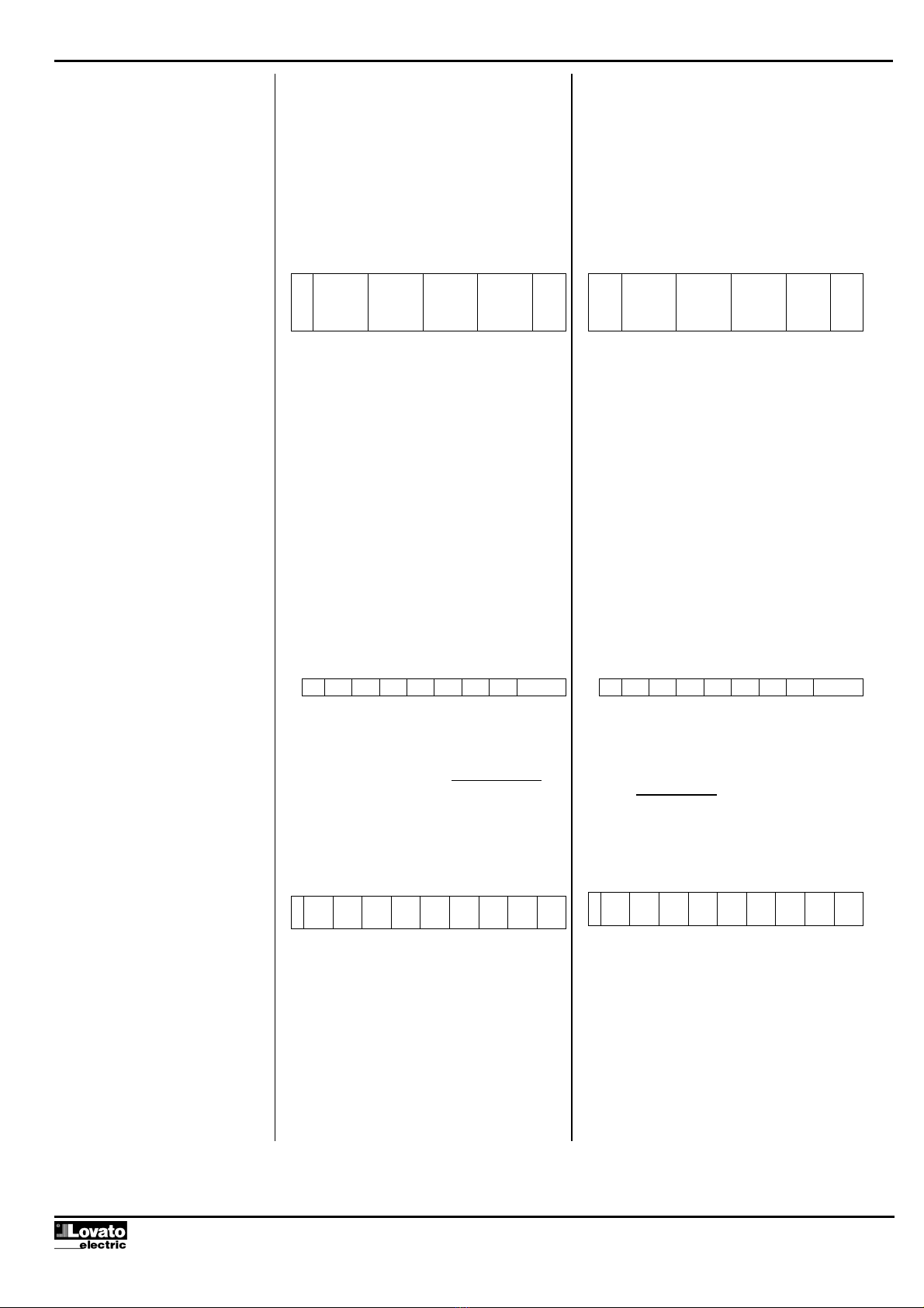
Risultato CRC 0001 0010
0100 0001
12h 41h
Nota: Il byte 41h viene spedito per primo (anche se
e’ il LSB), poi viene trasmesso 12h.
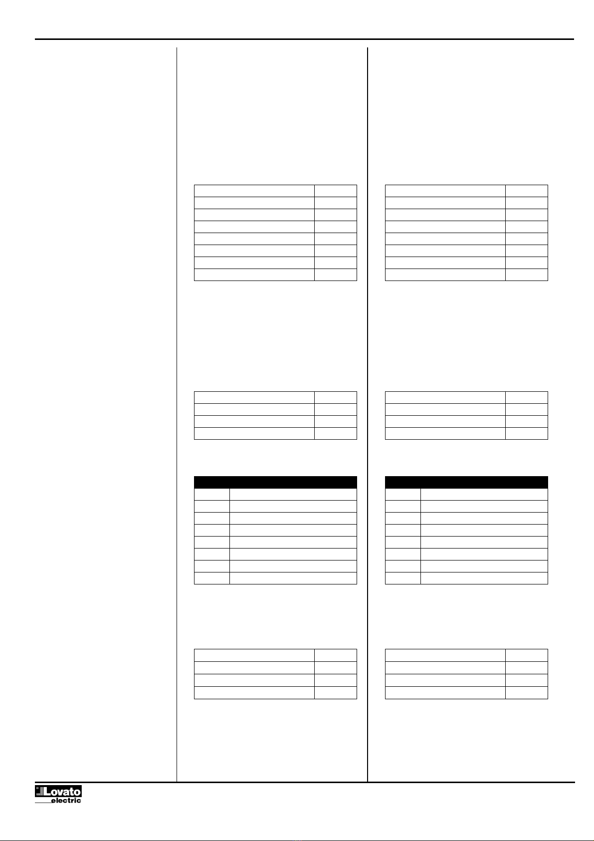
CALCOLO LRC (CHECKSUM per ASCII)
Esempio di calcolo:
Indirizzo 01 00000001
Funzione 04 00000100
Start address hi. 00 00000000
Start address lo. 00 00000000
Numero registri 08 00001000
Somma 00001101
Complemento a 1 11110010
+ 1 00000001
Complemento a 2 11110101
Risultato LRC F5
CRC CALCULATION (CHECKSUM for RTU)
Example of CRC calculation:
Frame = 0207h
CRC initialization 1111 1111 1111 1111
Load the first byte 0000 0010
Execute xor with the first 1111 1111 1111 1101
Byte of the frame
Execute 1st right shift 0111 1111 1111 1110 1
Carry=1,load polynomial 1010 0000 0000 0001
Execute xor with the 1101 1111 1111 1111
polynomial
Execute 2nd right shift 0110 1111 1111 1111 1
Carry=1,load polynomial 1010 0000 0000 0001
Execute xor with the 1100 1111 1111 1110
polynomial
Execute 3rd right shift 0110 0111 1111 1111 0
Execute 4th right shift 0011 0011 1111 1111 1
Carry=1,load polynomial 1010 0000 0000 0001
Execute xor with the 1001 0011 1111 1110
polynomial
Execute 5th right shift 0100 1001 1111 1111 0
Execute 6th right shift 0010 0100 1111 1111 1
Carry=1,load polynomial 1010 0000 0000 0001
Execute xor with the 1000 0100 1111 1110
polynomial
Execute 7th right shift 0100 0010 0111 1111 0
Execute 8th right shift 0010 0001 0011 1111 1
Carry=1,load polynomial 1010 0000 0000 0001
Load the second byte 0000 0111
of the frame
Execute xor with the 1000 0001 0011 1001
Second byte of the frame
Execute 1st right shift 0100 0000 1001 1100 1
Carry=1,load polynomial 1010 0000 0000 0001
Execute xor with the 1110 0000 1001 1101
polynomial
Execute 2nd right shift 0111 0000 0100 1110 1
Carry=1,load polynomial 1010 0000 0000 0001
Execute xor with the 1101 0000 0100 1111
polynomial
Execute 3rd right shift 0110 1000 0010 0111 1
Carry=1,load polynomial 1010 0000 0000 0001
Execute xor with the 1100 1000 0010 0110
polynomial
Execute 4th right shift 0110 0100 0001 0011 0
Execute 5th right shift 0010 0100 0000 1001 1
Carry=1,load polynomial 1010 0000 0000 0001
Execute xor with the 1001 0010 0000 1000
polynomial
Execute 6th right shift 0100 1001 0000 0100 0
Execute 7th right shift 0010 0100 1000 0010 0
Execute 8th right shift 0001 0010 0100 0001 0
CRC Result 0001 0010
0100 0001
12h 41h
Note: The byte 41h is sent first(even if it is the
LSB), then12h is sent.
LRC CALCULATION (CHECKSUM for ASCII)
Example of LRC calculation:
Address 01 00000001
Function 04 00000100
Start address hi. 00 00000000
Start address lo. 00 00000000
Number of registers 08 00001000
Sum 00001101
1. complement 11110010
+ 1 00000001
2. complement 11110101
LRC result F5
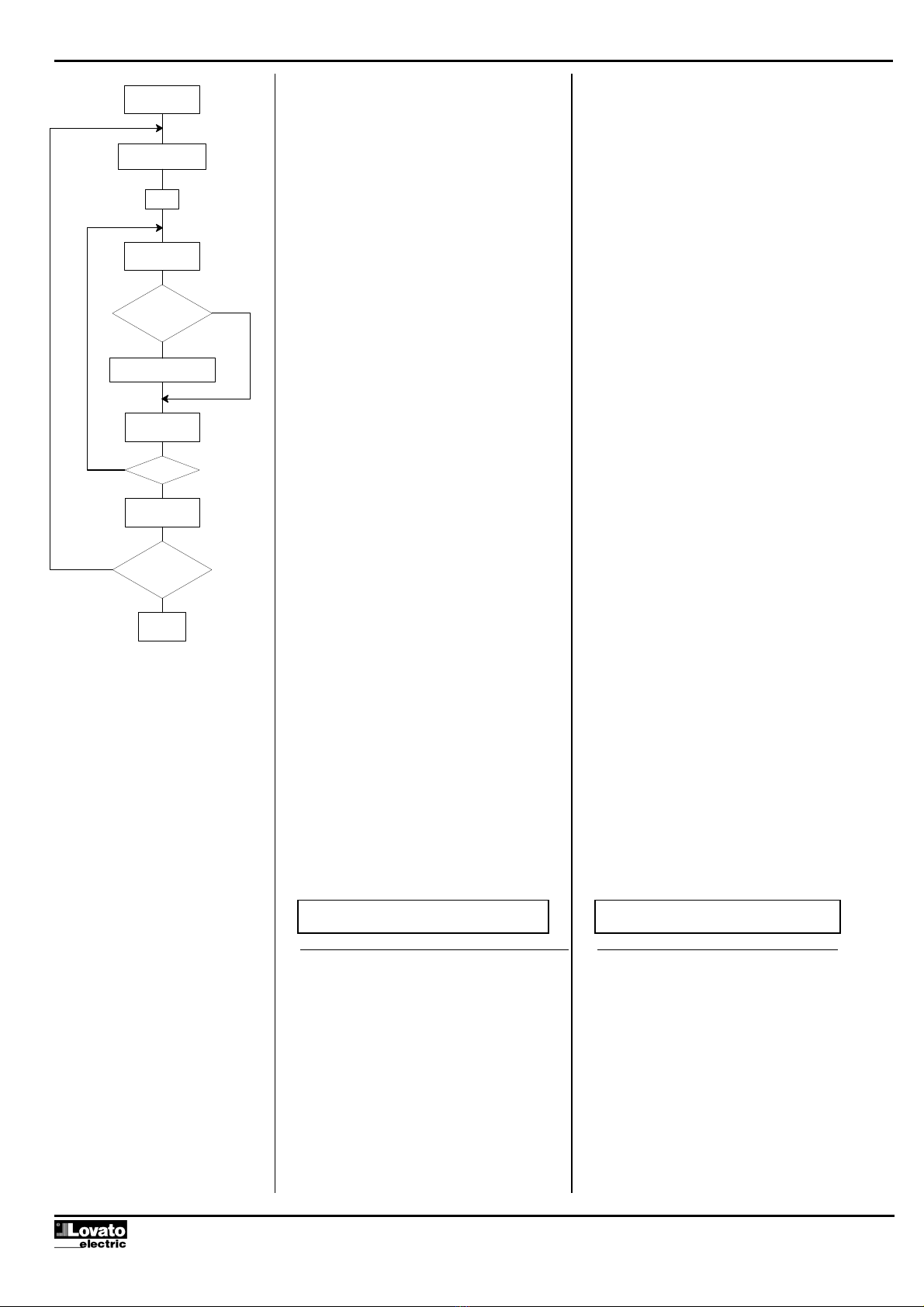
CRC xor BYTE = CRC
n = 0
CRC right shift
carry over
CRC xor POLY = CRC
n = n + 1
next BYTE
end message
End
n > 7
Hex FFFF = CRC
no
no
yes
yes