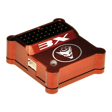
Bavarian Demon AXON User manual

PRODUCT-INFORMATION

EINBAU / MOUNTING
DE EN
ANSCHLUSS KABELBAUM
Roll/Ail
Nick/Elev
Pitch
Heck/Rud
Kopf-/Head Gyro
Horizont
Heck-/Tail Gyro
1
2
3
5
4
Servo 1
Servo 2
Servo 3
Servo 4
Heck/Rud
SERVO
RX
1
2
3
6
5
4
Servo 1
Servo 2
Servo 3
Servo 4
Heck/Rud
Gas/Thr/ESC
SERVO
ANSCHLUSS SUMME-IN/SUMME-OUT
1.RX
AUX / 2.RX
VORBEREITUNG
Die RC-Anlage muss mischerfrei, d.h. auf H1/
CCPM/Einzelservo, programmiert sein.
Folgende Anschlussoptionen des Empfängers
stehen zur Verfügung:
ANSCHLUSS VIA KABELBAUM
Kanäle gemäß Abbildung verkabeln. Hierzu
das jeweilige Kabel des Kabelbaums am ent-
sprechenden Kanal des Empfängers anschlie-
ßen.
Beispiel: Gelbes Kabel Empfängerausgang
Heckservo
Servos gemäß Abbildung an die Ausgänge 1-5
anstecken. Gas/ESC bleibt bei dieser Variante
direkt am Empfänger.
Achtung: Einadrige Kabel des Kabelbaums
müssen richtig herum auf „Impuls“ gesteckt
werden.
PREPARATION
Tx must be set to H1/CCPM/single servo, no
mixer active.
The following connection options are
available:
CONNECTION VIA CABLE LOOM
Connect each cable of the cable loom to the
appropriate channel on the receiver, according
to the diagram.
Example:
Yellow cable Rx port for tail servo
Connect servos to ports 1-5. Throttle/ESC
stays with the Rx.
Note: The loom‘s single-line cables must be
plugged the right way round into „signal pulse“.
ANSCHLUSS VIA SUMMENSIGNAL
Eingang B via Patch-Kabel mit dem Empfänger
verbinden, oder Spektrum-Satlliten seitlich an-
schließen (Master/Slave), und in der Software
während des Setups den Typ und die Kanalzu-
ordnung entsprechend einstellen.
DualRX-Option: s. Hauptanleitung und/oder
Software-Info.
Servos gemäß Abbildung an die Ausgänge 1-5
anstecken, Gas/ESC an Ausgang 6.
Beispiel: Senderkanal 4 = Heck
Kanalzuordnung Heck auf Kanal 4
einstellen
Heckservo auf Ausgang 5 stecken
CONNECTION VIA SERIAL-INPUT
Connect Rx to port B using a patch cable, or
conect Spektrum satellites on the side ports
(Master/Slave), and set the protocol type and
channel assignment during setup via software.
DualRX option: s. main manual and/or software
info.
Connect servos to ports 1-5, throttle/ESC to
port 6, according to the diagram.
Example: Tx channel 4 = tail servo
set channel assignment in software to 4
connect tail servo to port 5
HERZLICHEN GLÜCKWUNSCH
ZU IHREM NEUEN AXON.
Im Folgenden wollen wir Sie mit grundlegenden
Informationen zu Einstellung und Anschluss des
Systems vertraut machen. Das Grund-Setup
sowie jegliches Tuning wird ausschließlich über
die Einstell-Software erfolgen.
CONGRATULATIONS
ON YOUR NEW AXON.
Herewith we would like to supply you with initial
information about setup and connection of the
system. Basic setup and any tuning needs to
be carried out using the corresponding setup
software.
Master
Slave

BETRIEB
Beim Initialisieren nach dem Einschalten das
Modell und die Knüppel nicht bewegen.
Der Status der Initialisierung ist an den Servos
zu erkennen. Reagieren diese nicht auf Ein-
gaben und leuchtet gleichzeitig die LED nicht
konstant auf, so liegt einer der folgenden
Fehler vor:
Warte auf Eingangssignal: LED pulsiert rot
Fehler: System wegen Bewegung nicht initia-
lisiert!
Nach erfolgtem Initialisieren reagieren die
Servos auf Knüppelbewegungen sowie auf
Gyroeingaben beim Neigen des Helikopters.
LED leuchtet konstant betriebsbereit
KREISEL-MODUS
Bank gelb
Bank blau
Bank rot
Horizont-Modus: LED leuchtet konstant grün
Rettungsfunktions-Modus: LED immert grün
SETUP
Das Grund-Setup ist per Software durchzu-
führen. Dies kann im Experten-Modus oder
Assistent-geführt erfolgen.
Für das erstmalige Setup empfehlen wir die
Nutzung des Assistenten. Dies verhindert, dass
eine Einstellung übersehen wird.
INBETRIEBNAHME / COMMISSIONING
SETUP
Basic setup needs to be carried out using the
software. This can be done “manually” (Expert
mode) or wizard-guided.
For the rst setup we recommend to make use
of the wizard. This ensures that no setup step
will be missed.
OPERATION
Do not move model and sticks during
initialization after power-on.
The initializing status can be seen on the
servo’s reaction: are these not following any
Tx inputs, or does the LED not light up
constant, one of the following errors shows up:
Waiting for input signal: LED pulses red
Failure: system not initialized due to
movement!
After successful initialization, servos respond
to stick inputs and gyro corrections when tilting
the helicopter.
Constant LED light ready for operation
GYRO MODE
Bank yellow
Bank bue
Bank red
Horizon mode: Constant green LED light
Rescue mode: LED ickers green

-100 Norm HH +100
Heckkreisel / Tail gyro
INBETRIEBNAHME / COMMISSIONING
Detailed manual and
conguration software on
http://manuals.bavarianDEMON.com/
Ausführliche Anleitung und
Einstellsoftware auf
http://manuals.bavarianDEMON.com
Vol. 1.2
HECKKREISEL-KANAL
Steuert Heckkreisel-Empndlichkeit in Abhän-
gigkeit des Signalausschlags und den Kreisel-
Modus:
- Normal-Modus (Negatives Signal)
- Heading-Lock-Modus (Positives Signal)
Beispiel:
+45% Weg 45% Empf., Heading-Lock
RICHTUNGSTEST
Das Modell um jede Achse drehen.
Jeweilige Ausschläge müssen gegen die Dreh-
richtung arbeiten.
EINFLIEGEN
Für den Erstug immer mit dem Default
starten, ggf. eine der möglichen Voreinstellun-
gen für Modellgröße und Flugstil vorwählen.
Mit ca. 35-45% Empndlichkeit auf Kopf und
Heck beginnen und vorsichtig bis zum Opti-
mum steigern.
BANKUMSCHALTUNG
Über den Kopfkreiselkanal wird die aktive Bank
ausgewählt.
- Bank gelb (Negatives Signal)
- Bank rot (Mitten-Signal)
- Bank blau (Positives Signal)
KOPFKREISEL-KANAL
Neben der Bankumschaltung wird per Kopf-
kreisel die Kreiselempndlichkeit deniert (für
Bank gelb und Bank blau) in Abhängigkeit des
Signalausschlags.
Die Kreiselempndlichtkeit wird für Bank rot
über die Software eingestellt.
Beispiel: -60% Weg Bank gelb, 60% Empf.
BANK SWITCHING
Via head gyro channel the banks are
triggered.
- Bank yellow (negative signal)
- Bank red (center signal)
- Bank blue (positive signal)
HEAD GYRO CHANNEL
Besides bank switching, the head gyro chan-
nel’s travel setting denes the gyro gain (only
for bank blue and bank yellow).
Gyro gain for bank red to be set via software
only.
Example: -60% travel bank yellow, 60% gain
TAI GYRO CHANNEL
The tail gyro channel controls the tail gain, de-
ned by its travel setting, and the gyro mode:
- Normal mode (negative signal)
- Heading-lock mode (positive signal)
Example: +45% travel 45% gain, heading-lock
CHECK GYRO DIRECTION
Tilt model in each axis.
The corresponding control throw must act
against the tilt direction.
FLYING-IN
For the maiden ight always start with the de-
fault settings. In case, choose one of the pre-
sets from model size and ight style.
Start with 35-45% gain on head and tail and
increase carefully to the optimum.
-100 +1000
Kopfkreisel / Head gyro
Bank
gelb
yellow
Bank
blau
blue
Bank
rot
red
Other Bavarian Demon Other manuals
