Bavono BVP901 User manual

BVP901Intelligent Keyboard Instruction Manual
1
BAVONO BVP901 Manual
INDEX
I. KEYBOARD OVERVIEW................................................................................................................................................................2
II. INTELLIGENT KEYBOARD TECHNICAL PARAMETERS .....................................................................................................2
III. INTELLIGENT KEYBOARD DRAWING ....................................................................................................................................2
3.1 FRONT PANEL CHART AND FUNCTION KEY DESCRIPTION ................................................................................................ 2
3.2 INTELLIGENT KEYBOARD CONNECTION .......................................................................................................................... 3
IV. KEYBOARD OPERATION ...........................................................................................................................................................5
4.1 MENU CHART: .............................................................................................................................................................. 5
4.2 JOYSTICK OPERATION................................................................................................................................................... 5
4.3 CAMERA LENS CONTROL .............................................................................................................................................. 6
4.4 PRESET POSITION SETTING /ADJUSTING ....................................................................................................................... 6
4.5 THE KEYBOARD MENU .................................................................................................................................................. 6
4.5.1 THE SPEED DOME /DECODER SETTING .............................................................................................................. 6
4.5.2 SETTING KEYBOARD PARAMETERS .................................................................................................................... 10
4.5.2.1 ID NUMBER.......................................................................................................................................... 10
4.5.2.2 BAUD RATE .......................................................................................................................................... 10
4.5.2.3 SOUND .................................................................................................................................................11
4.5.2.4 MATCHING RESISTANCE (150Ω)...........................................................................................................11
4.5.2.5 PROTOCOL ...........................................................................................................................................11
4.5.2.6 TEST ....................................................................................................................................................11
4.5.2.7 MAX SECONDARY CONTROL DEVICES ................................................................................................... 12
4.5.2.8 MAX ALARM DEVICES 11 ........................................................................................................................ 12
4.5.3 WASH BRUSH................................................................................................................................................... 12
4.5.4 HEATER ........................................................................................................................................................... 12
4.5.5 AUXILIARY SWITCH 1 ........................................................................................................................................ 12
4.5.6 AUXILIARY SWITCH 2 ........................................................................................................................................ 12
4.5.7 MATRIX MENU .................................................................................................................................................. 13
4.5.8 PROPORTIONING THE JOYSTICK ........................................................................................................................ 13
4.6 LOCKING KEYBOARD................................................................................................................................................... 14
4.7 DEFENSE SETTING ..................................................................................................................................................... 15
V. COMMON KEY FUNCTIONS......................................................................................................................................................15
5.1 DEFAULT PROTOCOL OPERATING................................................................................................................................. 15
5.2 OTHER PROTOCOLS OPERATING ................................................................................................................................. 16
VI. TROUBLESHOOTING................................................................................................................................................................17

BVP901Intelligent Keyboard Instruction Manual
2
I. Keyboard Overview
The keyboard is used for controlling the intelligent dome. The keyboard is the main device between operator
and device in the monitoring system. It can be regarded as the main control keyboard and as the secondary
control keyboard.
Main Characteristics:
(1) Liquid Crystal Display the LCD display board is regarded as interface between operator and device. It is
direct, convenient, and easy to follow and conveys large amounts of information.
(2) Proportion Joystick (Options: PTZ control joystick and PT control joystick )
Use this joystick to operate high-speed dome. It is easy to use with good handling and flexible
maneuvering.
(3) The lock function of the keyboard can prevent unauthorized users to operate the keyboard.
(4) Provide RS-485 control output signal and also offer the standard RS-232 control signal.
II. Intelligent Keyboard Technical Parameters
2.1 Function Parameter
(1) Control Mode: Main、Secondary
(2) Max. connected secondary control keyboard: 16
(3) Max. controlled monitor: 64
2.2 Technical Parameter
(1) Communication baud rates: 1200 bps; 2400 bps; 4800 bps; 9600 bps
(2) Protocols: Default、PELCO-D、PELCO-P、Kalatel、Samsung
(3) Data Format: 1 starting bit, 8 data bits, 1 stopping bit
(4) Power input: DC 12V
III. Intelligent Keyboard Drawing
3.1 Front Panel Chart and Function Key Description

BVP901Intelligent Keyboard Instruction Manual
3
3.1.1 Function Area 1: Dome Camera Lens Control and Keyboard Lock and Unlock
(1) SHIFT key: Such as <SHIFT> + <Other Key> Selects alternate function of key.
(2) LOCK key: After pressing this key; input the password 6688, the keyboard is under locked status.
Open the keyboard by inputting 6688
3.1.2 Function Area 2: Menu Turning, Exit and Preset Position Set
(1) FUN key: Press the FUN key to select functions.
(2) EXIT key: Exit from function or function ladder.
(3) F1 Key: Keyboard menu cursor up.
(4) F2 key: Keyboard menu cursor down.
3.1.3 Number Area: Data Input, Clear and Confirmation
(1) CLR key: Clear the inputted number on the DATA display area. Press CLR to delete when
inputted number is wrong or needs to input it again.
(2) ENTER key: When you press the ENTER key, the inputted number in the Data area to select
function or step through ladder functions.
(3) 0~9 Number key: Number input.
3.1.4 Function Area 3: Dome Camera & Matrix Selection and Auto scanning Control
3.1.5 Joystick: Control Dome Camera running: Up, down, Left, Right, Left-up, Left-down, Right-up,
right-down, camera lens zoom in and zoom out.
2-Dimentional Keyboard joystick can’t control Dome Camera lens zoom in and zoom out.
Other functions are the same as 3-Dimentional keyboard
3.1.6 Data Display Area: Data Display
When the “DATA” column does not show “0”, the “DATA” column displays the Address of the dome
camera or decoder.
When the “DATA” column shows “0”, the “CAM” column displays the address of the dome camera or
decoder.
3.2 Intelligent Keyboard Connection
Insert RJ45 pin of transfer line offered with keyboard into RJ45 socket on keyboard’s back panel. As shown
below:

BVP901Intelligent Keyboard Instruction Manual
4
The leads of RJ45 socket show as left chart:
1:RS-485 D+ (yellow)
2:RS-485 D- (white)
7:Power Line POWER1-(black)
8:Power Line POWER2+(red)
RJ45 Socket
Keyboard Connection with Dome Camera & Matrix
RJ45 插座
BVP901Intelligent Keyboard Instruction Manual
5
IV. Keyboard Operation
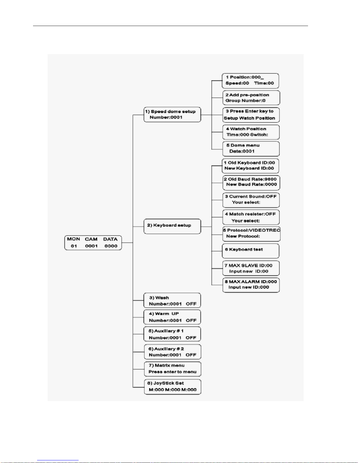
4.1 Menu Chart:
4.2 Joystick Operation
The joystick is used for controlling the moving direction of dome or high speed dome.
(1) 2-dimentional keyboard joystick
Move this joystick to operate dome or high speed dome. The running speed of the dome camera is a
direct ratio to the speed of the joystick. When the joystick is in the center, the dome or the high speed
BVP901Intelligent Keyboard Instruction Manual
6
dome stops running.
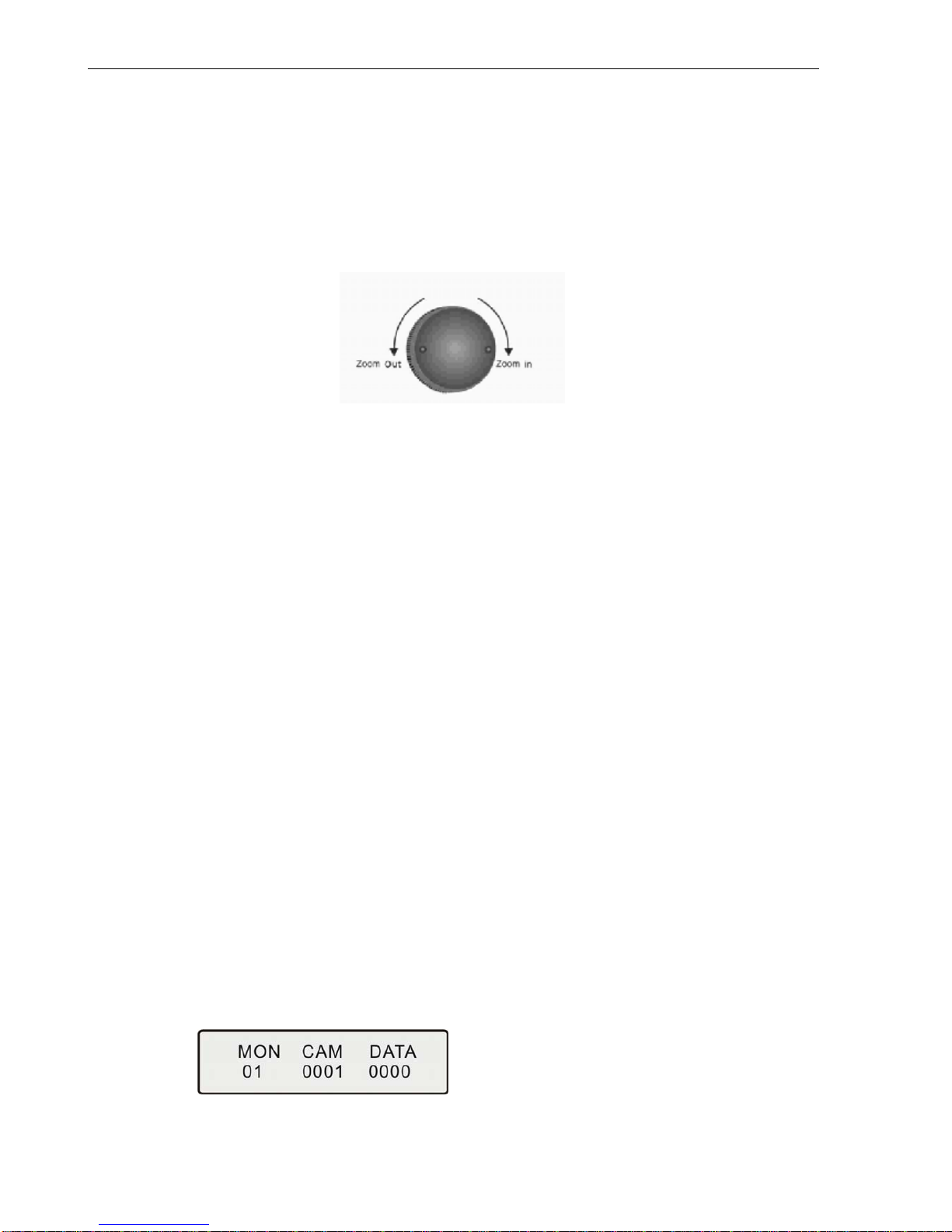
(2) 3-dimentional keyboard joystick
Move the joystick to control dome camera running: up, down, left, right, left-up, left-down, right-up,
right-down. These functions are the same as those of 2-dimentional keyboard joystick. The controlling
speed of lens is a direct ratio to the rotation speed of the joystick. When the joystick is in the center, the
lens stop controlling.
The joystick controls the lens as well as the running speed and direction of high speed dome, see as
follows:
4.3 Camera Lens Control
ZOOM in: zoom in
ZOOM out: zoom out
FOCUS far: focus far
FOCUS near: focus near
IRIS open: Iris big
IRIS close: Iris small
4.4 Preset Position Setting / Adjusting
Adjust the camera to the desired position including location, camera zoom, focus and iris. Enter the Preset
Position Number you wish to set, then the number shows in the DATA area. Press Shift + Call for final
confirmation. Preset position adjusting is to back to the position you preset, input the address of the dome
or decoder in the Data area, press CAM key to show in the CAM area. Input the preset position you would
like to view into the DATA area, press the Call key and the dome moves to the preset position.
Example: Set Preset Position No. 1:
(1) Move the keyboard joystick to the desired position and adjust the camera lens.
(2) Press CLR to clear the number in the data area.
(3) Enter the Preset Position Number 1.
(4) Press Shift + Call for final confirmation.
View preset position No. 1
(1) Press CLR to clear the number in the DATA area.
(2) Input the preset position number 1.
(3) Press the Call key. The dome will move to the Preset Position.
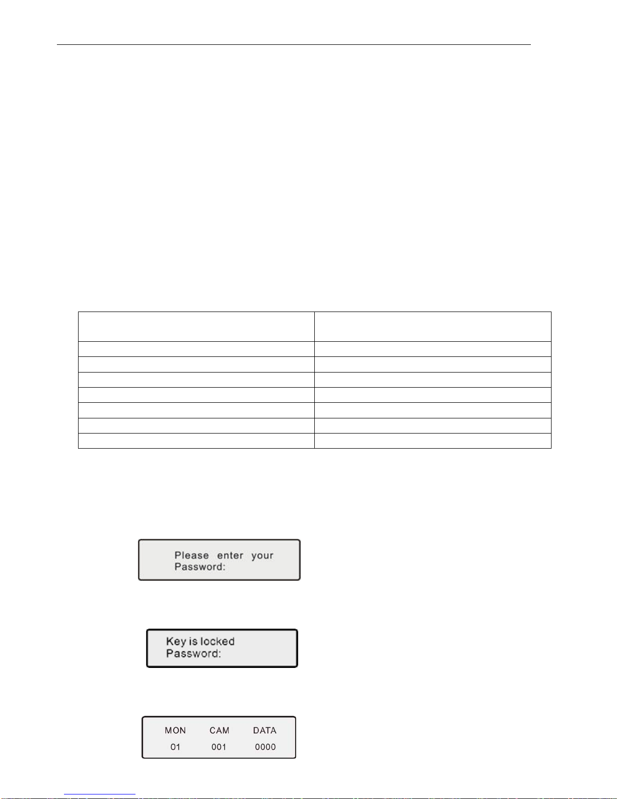
4.5 The Keyboard Menu
When the keyboard is under default (Main Menu) status, LCD displays as follows:
Input Monitor No. below DATA area and press MON key, the monitor number will display below MON area;
input the speed dome or decoder address below DATA area, the address will display below CAM area.
4.5.1 The Speed Dome / Decoder Setting
When the keyboard is under default (Main Menu) status (If not, press Exit key and exit to default
BVP901Intelligent Keyboard Instruction Manual
7
status)
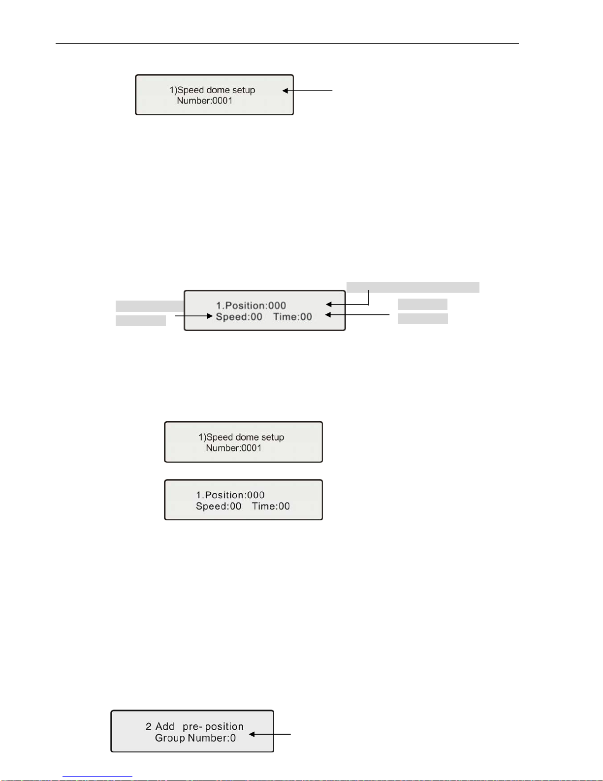
Press FUN key once, the keyboard displays:
Press ENTER key to the speed dome menu setting, the address is the same as before. Press FUN
key to the next.
4.5.1.1 Preset Position Speed and Dwell Time Setting
Dome Camera has the capacity to set up to 128 preset positions through the keyboard. It can set
the running speed to each preset position from 0.1°/s to 280°/s (1-64 Steps) and dwell time from
(1-60 seconds). User can set the parameters of dome camera preset positions through the
keyboard. (The dome can rotate at low speeds and at fast speeds. Its speed can be divided into 64
steps. 1 is the lowest speed and 64 is the fastest speed.)
Press FUN key until LCD displays:
When setting Speed and Time, the user should select the preset position in advance. Press F1 to
change cursor, press EXIT to move back to the main menu.
Example: Set the running speed of preset position No. 1 for Speed Dome 1 as Grade 64 (fastest
speed), dwelling time is 1 second.
(1) Press the FUN key until LCD displays:
Press Enter key, LCD displays:
(2) Press CLR key until Position:000_ displays 000_
(3) Input 1, press Enter.
(4) Press F1 to move cursor to Speed:00_
(5) Input 64, press Enter
(6) Press F1 to move cursor to Time:00_
(7) Input 1, press Enter
(8) Press Exit key and exit the setting
4.5.1.2 Pattern Tours Setting
Pattern Tours is an important function for high speed dome. The keyboard can set pattern tour
groups for the speed dome camera. Before setting the Pattern Tours, please set all preset positions
in advance. If the preset positions are not set the pattern tour will default to the pattern tour
parameter.
Press FUN key until LCD displays:
Running speed
(Input 1-64)
Preset
p
osition(In
p
ut 1-128)
Dwell time
(
In
p
ut 1-60
)
Press CLR key to delete value on DATA
column, input the speed dome or
decoder address (1-1024), press Enter
key for confirmation.
Displays the Group
Number (1-8)
BVP901Intelligent Keyboard Instruction Manual
8
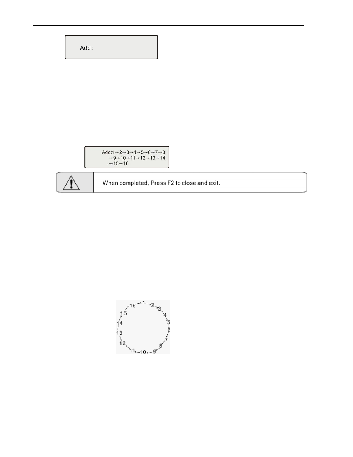
Input a Group number using the number keys, press Enter, the keyboard displays:
Input desired Pattern Tour (Preset Position No.) for the Group, press Enter for confirmation. One preset
position is added, press ENTER key for confirmation. When completed, Press F2 to close and exit,
press EXIT key and exit. This dome can set 8 cruise groups with a Max of 16 cruise points, can set the
preset positions repeatedly. (i.e. pattern tours route: 1 – 2 – 8 – 4 – 1 – 6 – 9 – 2 – 3 – 1 – 11 – 12 – 6 –
12 )
Example: To set 1-16 preset positions & parameter as the first pattern cruise group, the route is:
1 – 2 – 3 – 4 – 5 – 6 –7 – 8 – 9 – 10 – 11 – 12 –13 – 14– 15 – 16
The keyboard displays:
¾This dome can set 8 cruise groups with a Max of 16 cruise points. (1-128 points at any preset
position for each group)
¾Set the preset position at each of the cruise groups
¾Dwell time at each preset position can be customized at a different time (1-60 seconds). The speed
to each preset position can be different (1-64 grades)
¾Default cruise group will auto scan by starting at preset position point No. 1 to preset position point
No. 16.
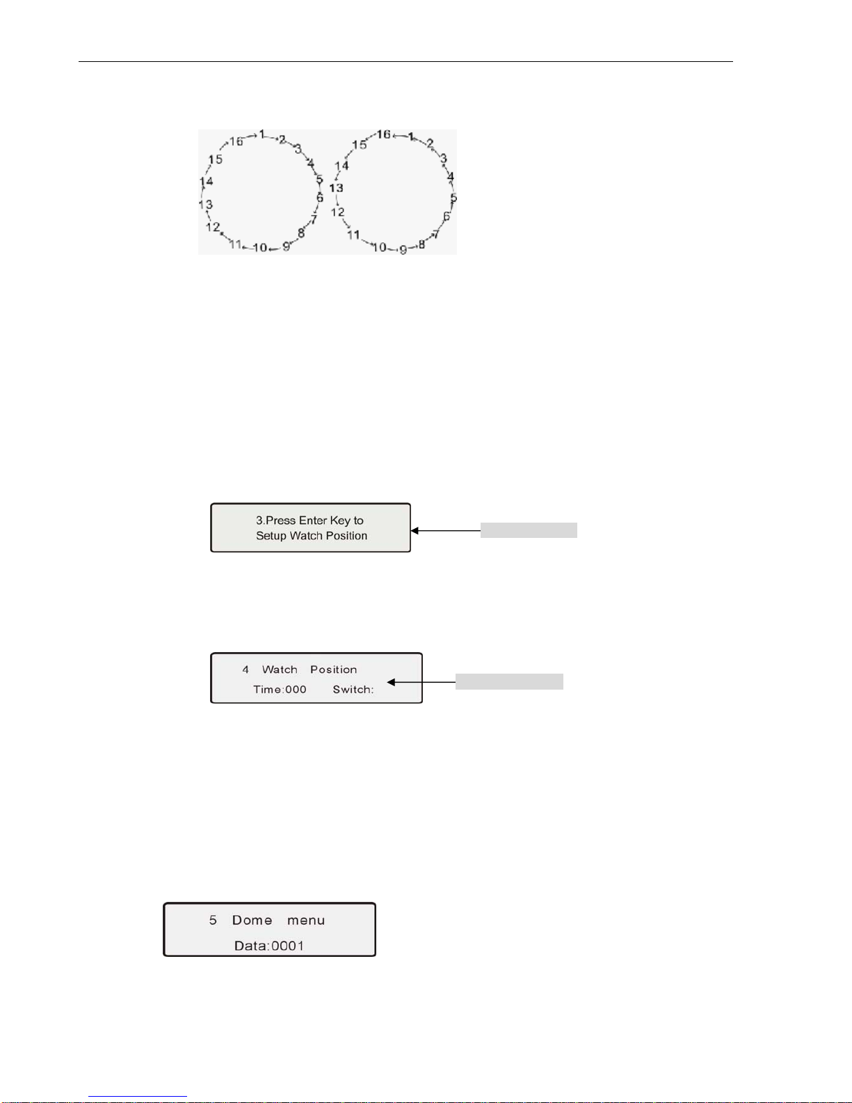
Two pattern tours styles can be used:
A .To-and-from Scanning
To-and-from Scanning is to make an auto circle scanning by points, see as follows:
To start up To-and-from Scanning: Input cruise Number, press SCAN key into to-and-from
scanning.
BVP901Intelligent Keyboard Instruction Manual
9
B. Cruise Scanning
Cruise Scanning is to make an auto cruise scanning, see as follows:
To start up Cruise Scanning: Input cruise Number, adjust key Shift + Scan into cruise scanning.
4.5.1.3 Guard Location Set
The guard location is an important position that the speed dome camera will come back to
automatically when there is no operation for a defined period. The user can set a guard location
and control the waiting time to the guard location, starting and stopping (1-255 seconds) before
allowing the camera to return to the guard location.
Press FUN key until LCD displays:
Press ENTER key to set the Guard Location. The position is set as the guard location. Press
Exit key and quit.
4.5.1.4 Guard Location Parameter Set
Press FUN key until LCD displays:
Time: 000 To set the waiting time
Switch: To set the guard location to start or stop
4.5.1.5 Speed Dome Menu
Press the FUN key until LCD displays:
Input the speed dome address, press ENTER key and enter OSD menu.
Location setting
Parameter setting
BVP901Intelligent Keyboard Instruction Manual
10
(1) Operating menu below for reference:
Operating Key Function
MON Dome menu cursor down
SEQ Dome menu cursor up
ACK Current Menu Confirmation
LIST Current Menu Change
ENABLE Menu Selection
(2) The four keys “SEQ”, “MON”, “Area” and “CAM” on the down-right of the keyboards stand for “UP”,
“DOWN”, “LEFT” and “RIGHT” respectively, they are used for OSD setting with default protocol. The
part of keyboard as illustrated in diagram below:
When other protocols,OSD menu entry and parameters setting should be chosen by selecting the
preset points as content in the table 1 below:
Table 1
Function How To Achieve
OSD MENU ENTRY CALL THE PRESET POINT 55
UP CALL THE PRESET POINT 56
DOWN CALL THE PRESET POINT 57
LEFT CALL THE PRESET POINT 58
RIGHT CALL THE PRESET POINT 59
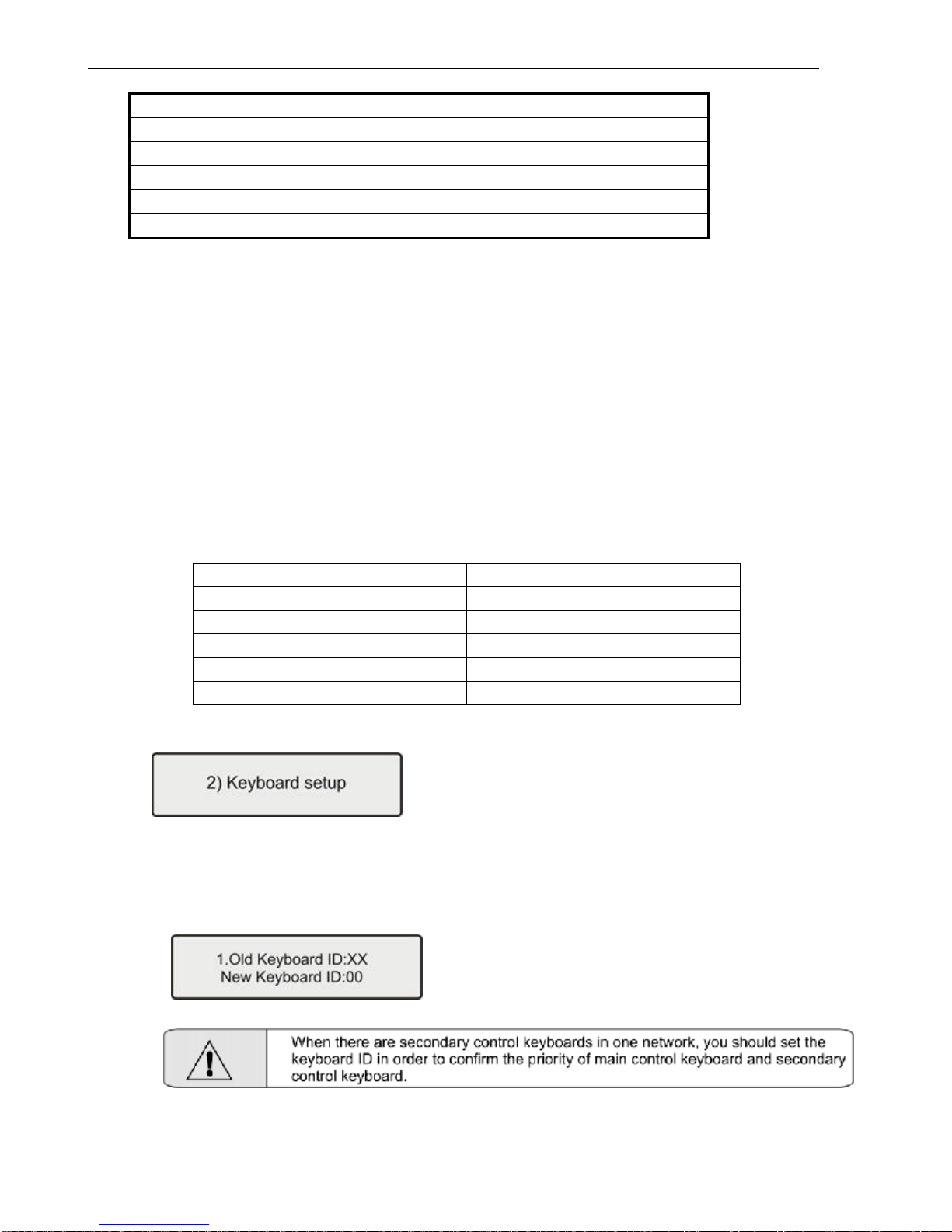
4.5.2 Setting Keyboard Parameters
When the keyboard is under default (Main Menu) status, press the FUN key until LCD displays:
Press the ENTER key to enter keyboard set up menu. Press the FUN key to choose and navigate the
submenu. Press the EXIT key to exit to the main menu.
4.5.2.1 ID Number
Press the FUN key until LCD displays:
Input the number (0-16), press ENTER for confirmation. New ID will be in effect immediately.
Note: ID: 00 Main Control Keyboard, ID: 01-16 Secondary Control Keyboard.
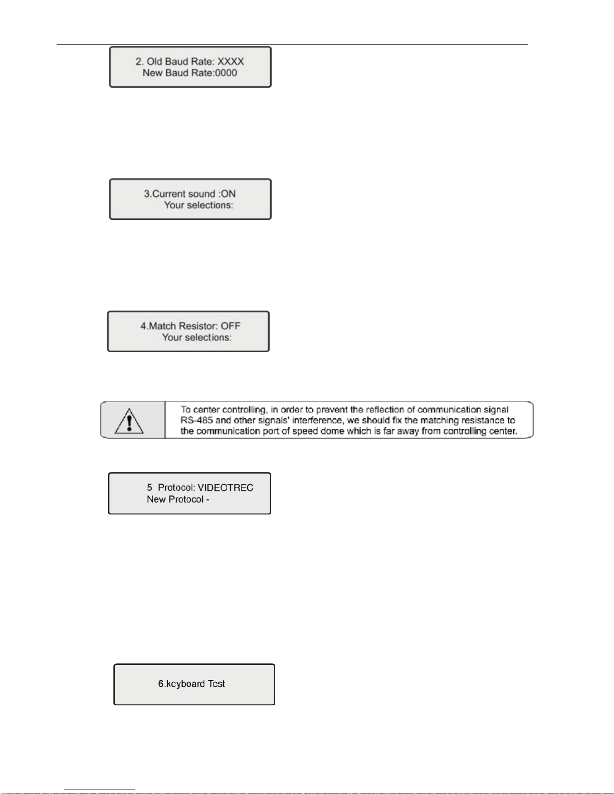
4.5.2.2 Baud Rate
Press the FUN key until LCD displays:
BVP901Intelligent Keyboard Instruction Manual
11
Optional baud rate: 9600 bps, 4800 bps, 2400 bps, and 1200 bps
Default baud rate: 9600bps.
Input your required baud rate in DATA area, and press the ENTER key for confirmation.
The new baud rate is in effect immediately.
4.5.2.3 Sound
Press the FUN key until LCD displays:
Press F1 key showing “ON”; turns on the sound function.
Press F2 key showing “OFF”; turns off the sound function.
Press the Enter key for confirmation. It is in effect immediately.
The normal sound status is OFF.
4.5.2.4 Matching Resistance (150Ω)
Press the FUN key until LCD displays:
Press F1 key showing “ON”, this will indicate resistance between RS-485 D+ and D-,
Press F2 key showing “OFF”, this will indicate no resistance between RS-485 D+ and D-,
Press the ENTER key for confirmation. The normal status is OFF.
4.5.2.5 Protocol
Press the FUN key until LCD displays:
Press “1” key showing “VIDEOTREC”, VIDEOTREC protocol
Press “2” key showing “PEL-D”, PELCO-D protocol
Press “3” key showing “PEL-P”, PELCO-P protocol
Press “4” key showing “KALATEL”, KALATEL protocol
Press “5” key showing “SAMSUNG”, SAMSUNG protocol
Press “ENTER” for confirmation. The new protocol is in effect immediately.
Default protocol is the VIDEOTREC Protocol.
4.5.2.6 Test
Press the FUN key until LCD displays:
Press the ENTER key for confirmation, a blank screen will appear. Press any key except the <EXIT>
key, the key name will display on the screen. Correct key names indicate proper operation of keys.
(Shift key can function when using with other keys) Press Exit key to leave the testing status and return
to the main menu.

BVP901Intelligent Keyboard Instruction Manual
12
4.5.2.7 Max Secondary Control Devices
Press the FUN key until LCD displays:
Input a number (00-16), Press “ENTER” for confirmation.
4.5.2.8 Max Alarm Devices 11
Press the FUN key until LCD displays:
Input number, the largest alarm input terminal number is 239. Press “ENTER” for confirmation
4.5.3 Wash Brush
When the keyboard is under default (Main Menu) status, press FUN until LCD display as below:
Set “Wash Brush” open by pressing down “F1/ON”key,
Set “Wash Brush” close by pressing down “F2/OFF”key.
4.5.4 Heater
When the keyboard is under default (Main Menu) status, press FUN until LCD displays as below:
Set “Heating” open by pressing down “F1/ON”key,
Set “Heating” close by pressing down “F2/OFF”key.
4.5.5 Auxiliary Switch 1
When the keyboard is under default (Main Menu) status, press FUN until LCD displays as below:
Set “Auxiliary Switch 1” on by pressing down “F1/ON”key,
Set “Auxiliary Switch 1” off by pressing down “F2/OFF”key.
4.5.6 Auxiliary Switch 2
When the keyboard is under default (Main Menu) status, press FUN until LCD displays as below:
Set “Auxiliary Switch 2” on by pressing down “F1/ON”key,
Set “Auxiliary Switch 2” off by pressing down “F2/OFF”key.
Press CLR key to delete previous data, input the
address of speed dome/decoder, press Enter key
for confirmation.
Press CLR key to delete previous data, input the
address of speed dome/decoder, press Enter key
for confirmation.
Press CLR key to delete previous data, input the
address of speed dome/decoder, press Enter key
for confirmation.
Press CLR key to delete previous data, input the
address of speed dome/decoder, press Enter key
for confirmation.

BVP901Intelligent Keyboard Instruction Manual
13
4.5.7 Matrix Menu
When the keyboard is under default (Main Menu) status, press FUN until LCD displays as below:
Press ENTER key to enter the menu of matrix.
There will be the default data of the menu of matrix display showing the following information on the LCD:
The details of operation are in the table below:
Operation Key Functions
F1 Up
F2 Down
ENTER Enter Submenu
MPX Return to the Previous Menu
When in data column, input data and hit enter key. Change the data in the menu of the matrix
EXIT Return to the Previous menu of the Function
4.5.7.1 Monitor Selection
(1) Press CLR key, delete value in the DATA area at right-up side of LCD.
(2) Input monitor No. in DATA area, it displays on LCD.
(3) Press MON key, clear monitor No. in DATA area, monitor No. displays in MON area.
Example: Select No.2 Monitor:
PressCLRkey;
Press Number key 2;
Press MON key;
When completed, Monitor 2 is the current monitor.
4.5.7.2 Switch one video signal of dome camera to the monitor selected
(1) Press CLR key, delete value in the DATA area;
(2) Input the speed dome address which is opposite to video signal input, it displays in the DATA
area;
(3) Press CAM key, delete value in the DATA area, the speed dome address displays in CAM area;
the speed dome screen will switch to the monitor you selected and display the related
information.
4.5.7.3 Group Switch
Input number (1-99) in DATA area, press GRP key for confirmation
4.5.7.4 Order-switch Startup
Press SEQ key, if showing 0 in DATA area, order-switch parameter (1-99) is in MON area.
4.5.7.5 Order-switch Stop
Press Shift + SEQ key for stopping order-switch
4.5.8 Proportioning the Joystick
When the keyboard is under default (Main Menu) status, press FUN until LCD display as below:
BVP901Intelligent Keyboard Instruction Manual
14
4.5.8.1 To set Joystick middle value
Press the “AUTO” key to set the middle position when joystick stands at the center-point.
4.5.8.2 To Set the Maximum Upward Movement Data Setting
Move the joystick all the way up and press “ACK” key to set the relevant maximum data.
4.5.8.3 To set the Maximum downward Movement Data Setting
Move the joystick all the way down and press “LIST” key to set the relevant maximum data.
4.5.8.4 To set the Maximum leftward Movement Data Setting
Move the joystick all the way left and press “PAN_A” key to set the relevant maximum data.
4.5.8.5 To set the Maximum rightward Movement Data Setting
Move the joystick all the way right and press “PAN_B” key to set the relevant maximum data.
4.5.8.6 Maximum Counter-clockwise Data Setting (Available on 3-dimentional Keyboards only)
Turn joystick all the way counter-clockwise and press “SEQ” key to enter the relevant maximum
data setting.
4.5.8.7 Maximum Clockwise Data Setting (Available on 3-dimentional Keyboards only)
Screw clockwise the middle pillar to its maximum and press “NEXT” key to finish the relevant
maximum data setting.
The details of operation are in the table below:
Operation Key Functions
SEQ for Maximum Counter-clockwise Data Setting
NEXT for Maximum Clockwise Data Setting
PAN_A for Maximum leftward Movement Data Setting
PAN_B for Maximum rightward Movement Data Setting
ACK for Maximum upward Movement Data Setting
LIST for Maximum downward Movement Data Setting
AUTO for Joystick middle status Setting
4.6 Locking Keyboard
(1) Keyboard Lock Setting
The lock function of the keyboard can prevent unauthorized users to operate the keyboard. When the
system is locked, only the administrator can unlock the system. When the keyboard is locked, input the
system password to unlock the keyboard.
To lock the keyboard: Press down the LOCK key, LCD displays:
Input password: 6688 (This password is set by the factory and cannot be modified). Once entered,
keyboard will be in locked status. It shows:
When the keyboard is locked, the users cannot operate the keyboard.
To unlock the keyboard: Input the password 6688, then press the ENTER key for confirmation. The
keyboard will go back to the last screen before it was locked.

BVP901Intelligent Keyboard Instruction Manual
15
(2) Password Setting
The keyboard password is 6688, this is an unchangeable password and only for the administrator. We
suggest you not open this password.
4.7 Defense Setting
(1). Defense setting: input alarm code 1-4 + Enable
(2). Defense withdraw: input alarm code 1-4 + Shift + Enable
(3). Alarm stop: press Shift + CLR key
(4). Defense Status Checking: press ACK key, when showing ON in DATA area, defense setting; OFF as
defense withdraw.
V. Common Key Functions
5.1 Default Protocol Operating
Key Function
Call Adjust preset position
Shift + Call Set preset position
Pan -A Limited Site A
Pan -B Limited Site B
Auto Line Scan (scanning between two points)
Shift _Auto Panel Scanning (Mode Scanning)
Scan Start up the perambulate group
Shift + Scan Start up intercourse perambulate group
CAM LCD show CAM area address
MON Select Monitor
GRP Group Switch
Shift + GRP Group Auto-switch
SEQ Startup Order Switch
Shift + SEQ Stop Order Switch
ACK Defense setting/withdraw Checking (ON/OFF)
ENABLE Defense Setting
Shift + ENABLE Defense Withdraw
Shift + CLR Alarm Stop

BVP901Intelligent Keyboard Instruction Manual
16
5.2 Other Protocols Operating
5.2.1 Functions with Camera OSD Menu
Chart 1 Speed Dome Functions by Adjusting Preset Position
Preset Position Code Function
51 Start Point A to B scanning (low-speed)
52 Start Point A to B scanning (mid-speed)
53 Start Point A to B scanning (high-speed)
54 Start No. 1 auto-cruise
55 Into Camera OSD Menu
56 Cursor (Up)
57 Cursor (down)
58 Cursor (left)
59 Cursor (right)
60 Delete Alarm Status
61 Start Cruise
64 Start 360ºScanning
Chart 2 Speed Dome Functions by Loading Preset Position
Preset Position Code Function
51 Set Point A
52 Set Point B
53 Set Guard Location
54 Guard Location Open
55 Guard Location Close
5.2.2 Functions with Speed Dome OSD Menu
Chart 1 Speed Dome Functions by Adjusting Preset Position
Preset Position Code Function
51 Start Point A to B scannin
g
(
low-s
p
eed
)
52 Start Point A to B scannin
g
(
mid-s
p
eed
)
53 Start Point A to B scannin
g
(
hi
g
h-s
p
eed
)
54 Start No. 1 auto-cruise
55 Into S
p
eed Dome OSD Menu
56 Cursor
(
U
p)
57 Cursor
(
down
)
58 Cursor
(
left
)
59 Cursor
(
ri
g
ht
)
60 Delete Alarm Status
61 Start Cruise
64 Start 360ºScannin
g

BVP901Intelligent Keyboard Instruction Manual
17
Chart 2 Speed Dome Functions by Loading Preset Position
Preset Position Code Function
51 Set Point A
52 Set Point B
53 Set Guard Location
54 Guard Location Open
55 Guard Location Close
61 Run Pattern
62 Stop Pattern
VI. Troubleshooting
Exception phenomena Possible reason Relative solution
No display on the screen
when the power on
Power supply is not
connected properly
1.Check connection of power line
2.See if power supply is DC 12V
No way to control
designated dome or high
speed dome
1.Protocol is not correct
2.Baud rate is not
correct
3.Controlled address is
not correct
1. Check if the keyboard protocol accords with
that of dome or high-speed dome or not.
2. Check if the baud rate of the keyboard
accord with that of dome or high-speed
dome or not.
3. The number in CAM or DATA area can’t
accord with the object address
No Beep sound when
pressing key
Key-press sound is
closed
Start up key-press sound in the keyboard set
The speed dome is
controlled not so fast
The joystick is not set
correctly
Reset the joystick value according to 4.2.8
Other phenomena Back to manufacturer for maintenance
Table of contents


