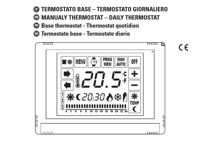
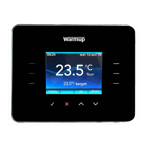
Bay Controls BW-WT2 User manual

Owner's Manual
[ S/N LABEL HERE ]
Document # BW-WT2DOC

BAYweb The mostat Model BW-WT2 Owne 's Manual
Copy ight © 2009 Bay Cont ols, LLC
Pa t Numbe : BW-WT2DOC
Revision: 1.1 Novembe 11, 2009
BAYweb and Plug-N-Go a e t adema ks of Bay Cont ols, LLC.
Patent pending technologies a e used in the BAYweb The mostat.

Table of Contents
Int oduction.............................................................................................................1
About This Manual..................................................................................................1
Safety P ecautions..............................................................................................1
Labels.................................................................................................................2
Limited Wa anty.................................................................................................3
Limitation on Liability..........................................................................................3
Unautho ized Repai ...........................................................................................3
Installation...............................................................................................................4
Ove view.............................................................................................................4
Identify Wi ing.....................................................................................................6
Install Cont ol Module.........................................................................................8
Install The mostat Keypad................................................................................10
Connect to the Inte net.....................................................................................12
Configu e the The mostat.................................................................................13
Test Ope ation..................................................................................................14
Ope ation..............................................................................................................15
Using the The mostat Keypad..........................................................................15
Using the Web Po tal........................................................................................15
Using You Mobile Phone.................................................................................16
Occupancy Sensing..........................................................................................16
Implementing Occupancy Sensing...............................................................16
Testing Occupancy Sensing.........................................................................17
Occupancy Sensing with Multiple The mostats...........................................17
Ale ting..............................................................................................................18
Implementing Ale ting...................................................................................18
Testing Ale ting.............................................................................................18
Refe ence..............................................................................................................19
The mostat Keypad..........................................................................................19
E o Codes..................................................................................................19
Cont ol Module.................................................................................................20
Ale t Inputs...................................................................................................20
The mostat Connecto ..................................................................................20
Fu nace/AC Connecto .................................................................................21
LAN Po t.......................................................................................................21
Line Powe ....................................................................................................21
Status Indicato s...........................................................................................21
T oubleshooting................................................................................................22
Solutions to P oblems..................................................................................23
Obtaining Suppo t........................................................................................25
Zone Cont ol.....................................................................................................27
The mostat Connections..................................................................................27
The mostat Wi ing............................................................................................27
Cont ol Module Te minals.................................................................................27
Specifications........................................................................................................28

Introduction
Thank you fo pu chasing the BAYweb The mostat. You now have one of the most advanced
Heating, Ventilating, and Ai Conditioning (HVAC) cont ol systems available today.
This the mostat is easily installed by home owne s o HVAC p ofessionals. It can be used to
eplace an existing the mostat o fo installation with new heating o cooling equipment.
This model of the BAYweb The mostat (BW-WT2) is designed fo use with conventional o
heat pump based systems, that use single o multistage stage cont ol.
About This Manual
This manual contains the info mation necessa y fo installing and ope ating the BAYweb
The mostat. Howeve , since installations may va y, these inst uctions may not cove all details
o va iations in the equipment supplied o eve y question that may possibly a ise du ing use.
If a question o situation develops which is not answe ed di ectly in this manual, contact
BAYweb suppo t fo specific answe s and advice.
You should become familia with the contents of this manual befo e the the mostat is put into
se vice. This is pa ticula ly impo tant with ega d to the safety p ecautions listed in the
Int oduction section, and those included at elevant points in othe sections of this manual.
Note that this manual is updated pe iodically. You can download the latest ve sion at
www.bayweb.com.
CAUTION: Read, be su e to clea ly unde stand, and then ca efully follow all of the
di ections and p ocedu es included in this manual. Failu e to adhe e to the
guidelines and specific inst uctions p ovided could cause equipment damage and
se ious pe sonal inju y o death.
Safety Precautions
Low voltage the mostats, including the BAYweb The mostat, use 24 VAC cont ol signals
limited to 3.2 ampe es to inte face to you fu nace and ai conditioning equipment. These low
voltage cont ol signals do not no mally ep esent an elect ic shock haza d unless used in an
envi onment fo which the equipment was not designed fo , such as a wet location.
The BAYweb The mostat is independently powe ed f om a line co d connected to a standa d
120 VAC elect ical outlet. This line voltage does ep esent an elect ical shock haza d if
imp ope ly used. Do not cut o modify the line co d in any way. Do not use a damaged line
co d. Do not emove the cove of the cont ol module. Do not expose the cont ol module to
wate . Do not plug in the cont ol module when wet.
Bay Cont ols, LLC. exp essly disclaims esponsibility o liability fo any inju y o damage
1
!

caused by failu e to obse ve specified o othe common safety p ecautions o failu e to
exe cise o dina y caution, common sense, and due ca e equi ed in installing and ope ating
the the mostat even though not specified he ein.
The ale t message shown he e appea s th oughout this manual to indicate those situations
and times when special ca e is necessa y to p event equipment damage o pe sonal inju y.
CAUTION: This indicates that the e could be the possibility of equipment damage
o pe sonal inju y.
CAUTION: If this equipment is used in a manne not specified by Bay Cont ols,
LLC., the e may be a isk of equipment damage, se ious pe sonal inju y, o death.
Labels
The following safety labels ale ts the installe o ope ato to possible haza ds and se ves to
emind the use of specific safety p ecautions. Befo e installing and/o ope ating this
the mostat, be ce tain to eview the pe tinent safety labels.
CAUTION: Read owne 's manual befo e installing o ope ating. Do not emove the
cove . No use se viceable pa ts inside.
CAUTION: High – Voltage Disconnect powe befo e se vicing.
Line Power 120 VAC, 0.25 A
2
!
!
!
!
!

Limited Warranty
Subject to the limitations contained below, and except as othe wise exp essly p ovided
he ein, Selle wa ants to the Buye that all tangible a ticles supplied by Selle o se vices
p ovided by Selle will be f ee of defects in mate ials o wo kmanship unde no mal use and
ca e until the expi ation of the applicable wa anty pe iod. Goods a e wa anted fo five (5)
yea s f om the date of pu chase. If Buye discove s any defects and notifies Selle the eof in
w iting du ing the applicable wa anty pe iod, Selle shall at its option p omptly co ect, epai ,
o eplace F.O.B. point of manufactu e that po tion of the good found by Selle to be defective,
o efund the pu chase p ice of the defective po tion of the goods/se vices. All eplacements
o epai s necessitated by inadequate maintenance, no mal wea and usage, unsuitable
powe sou ces, unsuitable envi onmental conditions, accident, misuse, imp ope installation,
modification, epai , sto age o handling, o any othe cause not the fault of Selle a e not
cove ed by this limited wa anty, and shall be at Buye ’s expense. Selle shall not be obligated
to pay any costs o cha ges incu ed by Buye except as may be ag eed upon in w iting in
advance by an autho ized Selle ep esentative. Goods epai ed and pa ts eplaced du ing
the wa anty pe iod shall be in wa anty fo the emainde of the o iginal wa anty pe iod o
ninety (90) days, whicheve is longe .
THERE ARE NO REPRESENTATIONS OR WARRANTIES OF ANY KIND, EXPRESS OR
IMPLIED, AS TO MERCHANTABILITY, FITNESS FOR PARTICULAR PURPOSE, OR ANY
OTHER MATTER WITH RESPECT TO ANY GOODS OR SERVICES.
Limitation on Liability
THE SOLE AND EXCLUSIVE REMEDY FOR BREACH OF WARRANTY HEREUNDER
SHALL BE LIMITED TO REPAIR, CORRECTION, REPLACEMENT OR REFUND OF
PURCHASE PRICE AS PROVIDED UNDER THE FOREGOING LIMITED WARRANTY.
IN NO EVENT, REGARDLESS OF THE FORM OF THE CLAIM OR CAUSE OF ACTION
(WHETHER BASED IN CONTRACT, INFRINGEMENT, NEGLIGENCE, STRICT LIABILITY,
TORT OR OTHERWISE), SHALL SELLER’S LIABILITY TO BUYER AND/OR ITS
CUSTOMERS EXCEED THE PRICE TO THE BUYER OF THE SPECIFIC GOODS
SUPPLIED OR SERVICES PROVIDED BY SELLER GIVING RISE TO THE CLAIM OR
CAUSE OF ACTION.
BUYER AGREES THAT IN NO EVENT SHALL SELLER’S LIABILITY TO BUYER AND/OR
ITS CUSTOMERS INCLUDE “CONSEQUENTIAL DAMAGES”. FOR THIS PURPOSE,
“CONSEQUENTIAL DAMAGES” SHALL INCLUDE, BUT NOT BE LIMITED TO, LOSS OF
ANTICIPATED PROFITS, LOSS OF USE, LOSS OF REVENUE AND LOSS OF CAPITAL.
Unauthorized Repair
In the event that the owne allows the Web The mostat to be se viced o epai ed by
unautho ized pe sonnel, the cove age of the o iginal wa anty policy will be automatically
te minated.
3

Installation
Overview
Installing the the mostat is a elatively simple p ocess and typically takes f om 10 to 30
minutes to complete. You should conside the cu ent outdoo tempe atu e. If unexpected
p oblems occu , you do not want to isk f eezing o ove heating, while you a e so ting the
p oblem out.
You will need sc ewd ive s, a wi e st ippe /cutte , and a d ill fo installing the wall ancho s to
complete the installation. A volt/ohm mete can be helpful fo t oubleshooting but is not
equi ed.
Most conventional the mostats, p obably including the one you a e eplacing, use a single
wall mounted enclosu e. The BAYweb the mostat uses two modules: the The mostat Keypad
and the Cont ol Module. This design eliminates the use of batte ies and potential need to pull
new wi e out to the wall, and esults in a mo e compact and elegant design.
The The mostat Keypad is mounted on wall in place of
you existing the mostat.
If you existing the mostat is la ge than the new one,
you can easily pull off the keypad late to touch up the
paint afte you have completed the installation.
The cont ol module mounts nea o on you
fu nace and/o ai conditione , and is spliced
into you existing the mostat wi e.
The module should ideally be powe ed f om
an outlet on the same ci cuit as you fu nace.
You will need an Inte net connection fo the
Cont ol Module.
If it is not convenient to plug into you netwo k
the e, conside using an optional powe -line
Ethe net adapte .
4

You existing installation is should be
simila to this depiction.
You have a single the mostat cable
going between you wall mounted
the mostat and the fu nace.
The cable contains f om 2 to 5 wi es of
diffe ent colo s.
You BAYweb The mostat installation is shown below. The Cont ol Module is mounted nea
the fu nace o ai conditione and is wi ed into the existing the mostat cable. The cont ol
module is powe ed f om a standa d outlet.
The specific installation steps to eplace you existing the mostat with the new BAYweb
The mostat a e shown in the emainde of the installation inst uctions. If you a e installing the
the mostat with new equipment, the p ocess will be simila except fo emoval of the old
equipment.
CAUTION: Be su e to eview all of the installation steps befo e sta ting you
installation.
5
The mostat Cable
The mostat Cable
The mostat Cable
!

1Identify Wiring
The objective of this step is to identify how you the mostat wi ing is connected to you
fu nace, ai conditione , o heat pump. This will also dete mine what type of cont ol
scheme you system uses.
A) Tu n off all powe to you fu nace, ai conditione , o heat pump.
CAUTION: Ve ify that all powe has been tu ned off. Failu e to tu n powe
off may esult in pe sonal inju y, elect ic shock, and equipment damage.
B) Go to you existing the mostat and emove the cove o emove it f om the wall as
needed so you can see the te minals whe e the wi ing is attached.
C) Note what connections you system uses and ve ify that you the mostat is using the
co ect te minals with the co ect wi e colo as shown in the table below.
If you installation is using non standa d wi e colo s, you will have to note what colo is
being used fo what te minal and match you wi e colo s to the app op iate te minal.
Note that if you have a wi e connected to te minal “C” o “X”, it will not be used fo you
BAYweb The mostat installation.
Ter inal Function Standard Wire
Color
My Wire Color Connected
(Y/N) ?
R, Rh, o Rc 24 VAC Supply Red
W o W1 o
Aux
Heat o Aux Heat White
G Fan G een
Y o Y1 Cool Yellow
W2 2nd Stage Heat B own
Y2 2nd Stage Cool Light Blue
O Reve sing Valve O ange
B Reve sing Valve Da k Blue
E Eme gency Heat Va ies
C o X 24 VAC Retu n Blue o Black NOT USED
6
!

D) The following table shows what te minals a e used by the diffe ent cont ol methods.
Dete mine which cont ol method you system is using by matching which te minals a e
connected to you wi ing.
Ci cle the numbe of the system type that you have. You will use this info mation when
configu ing you the mostat in Step 5.
If you have a wi e connected to te minal “E”, you have a heat pump with an eme gency
heat function. If you do not also have a wi e connected to te minal “W” you will need to
connect the wi e connected to “E” to te minal “W”.
# Syste Type
Ter inals
W o W1 o Aux Y W2 Y2 O o B
1 Conventional Heat Only* Y
2 Conventional Cool Only* Y
3 Conventional One Heat/One Cool Y Y
4 Conventional Two Heat/One Cool Y Y Y
5 Conventional Two Heat/Two Cool Y Y Y Y
6 Conventional One Heat/Two Cool Y Y Y
7 Heat Pump One Heat/One Cool Y Y
8 Heat Pump Two Heat/One Cool Y Y Y
9 Heat Pump Two Heat/Two Cool Y Y Y
10 Heat Pump Th ee Heat/Two Cool Y Y Y Y
E) If you have any question on what system type you have, contact suppo t
(suppo [email protected]) o contact you local HVAC se vice company.
* NOTE: The BAYweb The mostat equi es at least 4 wi es in the the mostat cable
between the The mostat keypad and the Cont ol Module. If you have a heat o cool
only system that only has 2 wi es, you will need to install new the mostat wi e. It is less
desi able, but often possible to obtain satisfacto y ope ation using 3 wi es. Consult the
F equently Asked Questions section at www.bayweb.com fo mo e info mation.
7

2Install ontrol Module
A) Find you the mostat cable whe e it goes into the fu nace, ai conditione , o heat
pump. This is the same cable identified in Step 1 and should be the same colo and
thickness as that cable.
CAUTION: The e may be othe cables of simila colo connecting othe
devices such as a humidifie . Be su e to use the cable that uns back to you
the mostat and not one that is connected to anothe device. Connecting the
Web The mostat to the w ong cable can esult in elect ic shock and/o
equipment damage.
B) Mount the Cont ol Module using the following c ite ia:
◦Select a location nea the fu nace whe e the e is sufficient oom to mount the
Cont ol Module along whe e the the mostat cable uns. The the mostat cable will
need to each both the “The mostat” and “Fu nace/AC” te minals of the Cont ol
Module.
◦Select a location within 6 feet of a powe outlet, ideally on the same ci cuit as the
fu nace/AC, o heat pump.
◦Select a location whe e you can connect to the Inte net. If wi ing is not convenient,
we suggest using a powe line Ethe net adapte that will allow you to make this
connection using you existing powe wi ing.
C) P epa e the the mostat cable:
With the fu nace, ai conditione , o heat pump powe OFF, cut the the mostat wi e at a
point whe e both ends will be able to each the Cont ol Module mounting location.
Using a wi e-st ipping tool, st ip app oximately 2 inches of the oute jacket off both
ends of the the mostat cable, then st ip app oximately ¼ inch off the end of each of the
the mostat wi es.
D) Connect the wi ing going to the The mostat Keypad:
Attach the wi es in the cable coming f om the the mostat to the te minals on the LEFT
side of the cont ol module into the connecto labeled "Ther ostat". Be su e to match
the wi e colo and te minal designation as identified in Step 1. If you have mo e wi es
than the fou wi es labeled on the connecto (Red, White, G een, Yellow), bend them
back out of the way and tape to the cable. They will not be used.
Note that you need fou wi es between the Cont ol Module and The mostat Keypad
even if you have a heat o cool only system.
8
!

E) Connect the wi ing going to the fu nace, ai conditione , o heat pump:
Attach the wi es in the cable coming f om the fu nace to the te minals on the RIGHT
side of the cont ol module labeled "Furnace/AC". Be su e to match the wi e colo and
te minal designation as identified in Step 1.
CAUTION: It is ve y impo tant to connect the the mostat cable to the co ect
connecto s on the Cont ol Module. Failu e to do so may cause equipment
damage.
F) Confi m that the te minal sc ews a e tight, the wi es will not pull out of the te minals,
and that the e a e not any sho ts between te minals.
The Cont ol Module is mounted nea the
fu nace whe e the the mostat cable is outed.
This location should be within 6 feet of a
powe outlet.
You will connect the module to you netwo k
using standa d Ethe net cable, o using the
powe line Ethe net adapte s.
O ient the Cont ol Module so the Fu nace/AC
connecto is on the side that goes to the
fu nace, mounting it “upside down” if needed.
The Cont ol Module installed and wi ed to
you fu nace, ai conditione , o heat pump.
Do not plug in the Cont ol Module powe o
Inte net yet. This will be done in step 4.
9
!

3Install Thermostat Keypad
A) Remove the wi es f om you existing the mostat, taking ca e that the wi es do not fall
back into the wall.
B) Remove the existing the mostat and any associated mounting ha dwa e.
C) Fill in any holes f om the p evious the mostat mounting and paint the wall if needed.
D) Hold the The mostat Keypad in the desi ed position and ma k the location of the top
mounting sc ew. Locate the bottom mounting sc ew 3 ½ inches below the top sc ew
location. D ill 3/16 inch holes and install the supplied wall ancho s. Tap the ancho s
with the sc ewd ive handle to insu e that a e flush o slightly indented into the wall.
E) Sc ew the supplied mounting sc ews into the wall ancho s leaving about 1/16th inch
gap fo the The mostat Keypad to slide ove .
F) Make su e the ends of each wi e a e st ipped and eady to be attached to the new
The mostat Keypad. If any wi es b eak off then use you wi e st ippe to st ip
app oximately ¼ inch of insulation f om the end of the wi e.
G) Using the supplied wi e nuts, attach the fou colo ed wi es coming f om the The mostat
Keypad ( ed, white, g een, yellow) to the fou matching colo ed wi es f om the cable in
the wall. If you installation uses non standa d wi e colo s, use the table you completed
in step 1C to connect you wi e colo s to the standa d colo of the The mostat Keypad.
H) If you have any spa e wi es not being used, cut off any ba e sections and insu e that
they will not sho t to anything in the The mostat Keypad.
I) Push the the mostat cable into the wall to emove as much slack as possible. Fit the
any excess wi ing into the space behind the The mostat Keypad.
J) Attach the The mostat Keypad to the wall by sliding the slot at the top and key opening
at the bottom ove the ancho sc ews installed in step 3D above. The sideways key slot
will allow some side to side adjustment to facilitate ve tical alignment.
K) Check the fit to the wall. The The mostat Keypad should have a tight fit to the wall. If it
is too loose, sc ew the mounting sc ews in a bit fu the as needed to obtain a tight fit.
10

Wall mounting location with the existing
the mostat cable p epa ed to install the new
The mostat Keypad.
If the ends of the existing wi ing a e wo n o
b oken. Cut off the ends and st ip about ¼
inch of insulation f om the end of each wi e.
Now is a good time to touch up the paint if
needed.
Locate and install the wall ancho s and
mounting sc ews as shown, and desc ibed
above.
Connect the The mostat Keypad to you
the mostat wi ing as shown.
Route the slack in the the mostat cable and
wi ing back into the wall.
Keep the wi e connecto s (wi e nuts) on the
outside of the wall. They will fit inside the
The mostat Keypad when attached to the
wall.
Complete installation of the The mostat
Keypad by sliding it ove the ancho sc ews.
Be ca eful to not pinch o bunch up the wi ing
behind the module.
Adjust the ancho sc ews as needed to obtain
a tight fit flush to the wall.
11

4onnect to the Internet
The BAYweb The mostat is facto y configu ed fo system type 3, conventional one
heat/one cool. This will also wo k fo system types 1 and 2. If you have a multistage
fu nace, ai conditione , o heat pump, you will need to connect the the mostat to the
Inte net and configu e it fo the type of system that you have p io to use.
A) Connect the Cont ol Module to the Inte net. Plug one end of an Ethe net cable into the
LAN po t on the bottom of the Cont ol Module and the othe end into a po t on a oute
o switch on you home netwo k.
B) If di ect wi ing is not convenient, use Powe line Ethe net adapte s. Plug one adapte
into a powe plug nea the cont ol module, and the othe adapte nea you home
oute . Then just plug the Ethe net cables into the adapte s and the po ts.
C) The BAYweb The mostat does not equi e any configu ation o p og amming of you
netwo king equipment. You do not need to change secu ity settings. Just plug it in and
you a e all set to go.
D) Plug in the cont ol module. Do not powe up you fu nace, ai conditione , o heat pump
yet. The Powe LED on the cont ol module should illuminate.
CAUTION: To educe the isk of elect ic shock, this p oduct has a g ounding
type plug that has a thi d (g ounding) pin. This plug will only fit into a
g ounding type powe outlet. If the plug does not fit into the outlet, contact a
qualified elect ician to install the p ope outlet. Do not change the plug in any
way.
E) In less than a minute the “Uplink” light should illuminate on the cont ol module. If you
do not see “Uplink” light up within a couple of minutes, efe to the T oubleshooting
section of this manual.
12
!

5onfigure the Thermostat
The the mostat is configu ed using the BAYweb po tal. The following steps will guide you
th ough setting up you own pe sonal web po tal and configu ing the the mostat. If you have
al eady setup you own po tal, simply click on the “My Devices” link to add the the mostat.
A) Go to the BAYweb site by ente ing www.bayweb.com in the add ess ba of you web
b owse .
B) Click on the “C eate an account” link in the login box.
C) Ente the equested info mation.
D) You will be sent an email to confi m you have ente ed a valid email add ess and
validate you identity with the given email. You must follow the inst uctions in the email
to activate you account.
E) Once you account has been activated, login to you pe sonal web po tal at
www.bayweb.com using you use ID and passwo d.
F) Afte logging in, click on the “My Devices” link on the top ight of the page.
G) Click the “Add” button on the My Devices page.
H) Ente the se ial numbe and key code that a e p inted on the cove of this manual, and
can also be found on a label on the Cont ol Module.
I) When p ompted fo the “System Type”, ente the type you dete mined in installation
step 1D. Once this is complete, the the mostat is configu ed fo you specific
equipment.
13

6Test Operation
A) Tu n the powe back on to the fu nace, ai conditione , o heat pump.
B) Ve ify that the “Powe ” and “The mostat” lights a e illuminated on the cont ol module. If
eithe one is not on, efe to the T oubleshooting section of this manual.
C) Ve ify that the The mostat Keypad is showing the tempe atu e. If it is showing an “E”
with a numbe , this is an e o code. Refe to the T oubleshooting section.
D) Test FAN ope ation: P ess the keypad nea the “FAN” label. An LED should illuminate
next to the label and the fan should be unning. P ess FAN again and the fan will tu n
off. If the fan did not ope ate, consult the T oubleshooting section of this manual.
E) Test HEAT ope ation: Select heat mode by p essing the keypad nea the HEAT label,
an LED should illuminate next to the label. P ess the up a ow on the keypad to aise
the set point to at least 2 deg ees above the cu ent tempe atu e.
Check you fu nace o heat pump and confi m that it is heating. Note that you fan will
not un until you fu nace has heated up. This may take a few minutes.
Note that once the heat tu ns on, it will emain on fo a minimum of 1 minute and once
it tu ns off, if will emain off fo 1 minute as well.
If ope ating co ectly, go back to the keypad and change the set point back to a no mal
level. If heating did not function, efe to the T oubleshooting section.
F) Test COOL ope ation:
CAUTION: If the outdoo tempe atu e is below 40º F you should not un you
ai conditione as that may esult in equipment damage.
Select cool mode by p essing the keypad nea the COOL label. An LED should
illuminate next to the label. P ess the down a ow on the keypad to lowe the set point
to at least 2 deg ees below the cu ent tempe atu e.
Check you ai conditione o heat pump and confi m that it is unning.
G) If ope ating co ectly, go back to the keypad and change the set point back to a no mal
level. If cooling did not function, efe to the T oubleshooting section.
14
!

Operation
Using the Thermostat Keypad
The The mostat Keypad shows the cu ent tempe atu e, set point and modes, and allows you
to manually cont ol you fu nace and ai conditione .
Using the Web Portal
The eal powe of the BAYweb The mostat is ealized by using the BAYweb Po tal to access
you the mostat. This po tal can be accessed anytime f om anywhe e via web b owse and
Inte net enabled mobile phone. Unlimited use of the po tal is included at no cha ge.
If you have not al eady done so, setup you pe sonalized po tal by going to the web site
www.bayweb.com, egiste a new account, login and add a device (you the mostat). You will
need the se ial numbe and key code that a e on the f ont of this manual.
15
Indicato s show
Indicato s show
which modes a e
which modes a e
selected
selected
P ess once to show
P ess once to show
the cu ent set point.
the cu ent set point.
P ess again to
P ess again to
change.
change.
P ess to select
P ess to select
HEAT mode. If
HEAT mode. If
selected, p ess
selected, p ess
again to tu n OFF.
again to tu n OFF.
P ess to change
P ess to change
HOLD mode. If
HOLD mode. If
selected the
selected the
cu ent set point
cu ent set point
will be used
will be used
ega dless of
ega dless of
schedule.
schedule.
Cu ent
Cu ent
Tempe atu e
Tempe atu e
P ess to select
P ess to select
COOL mode. If
COOL mode. If
selected, p ess
selected, p ess
again to tu n OFF.
again to tu n OFF.
P ess to change
P ess to change
the FAN mode
the FAN mode
between AUTO
between AUTO
and ON.
and ON.

Using Your Mobile Phone
Once you have setup you pe sonalized web po tal, you can also use most any mobile phone
that has web access to emotely access you the mostat and othe web devices. To access
the mobile web po tal, ente the following add ess in you mobile phone b owse :
www.bayweb.com/mobile.
Occupancy Sensing
The BAYweb The mostat can use va ious types of senso s (motion senso s being the most
common) which allow the the mostat to “know” when you a e home (Occupied) o when you
a e away (Not Occupied).
Occupancy senso s enable the Web The mostat to ope ate as one of the most efficient
the mostat available today. Using occupancy senso s will save you the most amount of
money and simplify setting up you the mostat.
Using Occupancy Sensing allows you to only pay fo heating o ai conditioning to you
comfo t level when you a e the e. Imagine unning out to go shopping on a weekend and
being gone f om you house fo say 5 hou s. Do you always tu n you the mostat down when
you go shopping? Now you BAYweb The mostat can do it fo you.
Use of Occupancy Sensing simplifies setting up you the mostat’s schedule because all you
need to do is dete mine when you gene ally a e asleep and when you gene ally wake up (if
you want you house heated befo e you wake). The emainde of the time you can tell the
the mostat to sense if you a e the e o not.
While “Sensing”, the the mostat will automatically set back the tempe atu e to you “Away”
set point afte a pe iod of time of not sensing occupancy. Likewise, upon sensing occupancy,
it will switch to you “Ho e” set point.
Scheduling a “Sleep” activity disables Occupancy Sensing to p event switching to the Home
set point if you get up in the middle of the night and happen to pass a senso .
I ple enting Occupancy Sensing
To enable and use occupancy sensing you need to install one o mo e occupancy senso s
and configu e the the mostat to use them on the web po tal.
The the mostat can use wi eless (X10 wi eless p otocol) o wi ed occupancy senso s. Bay
sells a low cost wi eless occupancy senso that is eady to use with the BAYweb The mostat.
Just put in a couple of batte ies and mount it in a location that typically sees activity when you
a e home. You can use as many senso s as needed enabling the the mostat to monito
multiple locations in you home fo occupancy.
Wi ed occupancy senso s can use eithe no mally open o closed contacts. Motion senso s
f om most ala m systems a e compatible with the BAYweb the mostat.
16

Occupancy sensing with pets in the home is accomplished by masking off the lowe pa t of
the sensing lens.
You should locate you senso s in high-t affic a eas of you house so that they will be most
likely to sense when people a e p esent. The senso s f om Bay have a 10+ foot ange and will
sense people as they pass in f ont of the senso . We have found that locating them at about
chest height o highe wo ks well.
Once you have installed you occupancy senso s login to the web po tal to enable them. To
enable occupancy sensing select the “Schedule” page f om the the mostat applet menu and
set the “Occupancy Inactivity Time”. We suggest using 1 hou fo this inte val initially, you can
adjust this value late if needed to suit you lifestyle.
If you a e using senso s not supplied by Bay, you may need to configu e the the mostat to
look fo othe wi eless IDs o to monito the wi ed input. This is done on the “Settings” page of
the the mostat applet.
Afte enabling occupancy sensing eview you schedule and set you “Sensing”, “Sleep” , and
“Home” times as desc ibed above. You the mostat will now automatically adapt you HVAC
ope ation to match you lifestyle.
Testing Occupancy Sensing
If you want to see if the senso s a e wo king as expected, login to the web po tal and select
“Senso Log” f om the the mostat applet menu.
The the mostat applet “Ope ation Log” will give a detailed view of occupancy sensing
ope ation.
Occupancy Sensing with Multiple Ther ostats
If you a e using multiple BAYweb the mostats in the same building, and wish to have each
the mostat sense occupancy (using wi eless senso s) in sepa ate a eas, you will need to
configu e the occupancy senso s with diffe ent X10 device IDs.
The default X10 ID of Bay supplied senso s is “A1”. Note that these senso s also use an ID
that is one mo e than what is configu ed (default “A2”) fo othe pu poses, do not use the next
ID fo occupancy sensing. Fo example, acceptable IDs would be A1, A3, A5...
Refe to the inst uctions p ovided with the senso fo detail on how to change the senso 's
X10 ID. Configu e the the mostat to look fo the alte nate X10 IDs on the “Settings” page of
the the mostat applet.
17
Table of contents
