Read This Before Installing Thermostat
IMPORTANT
1
Read the entire installation section of this
Owner’s Manual thoroughly before you begin
to install or operate your Hunter Thermostat.
• Remove the mylar label from the display
window.
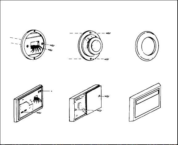
INSTALLATION
2
All installation is normally performed at your
thermostat.
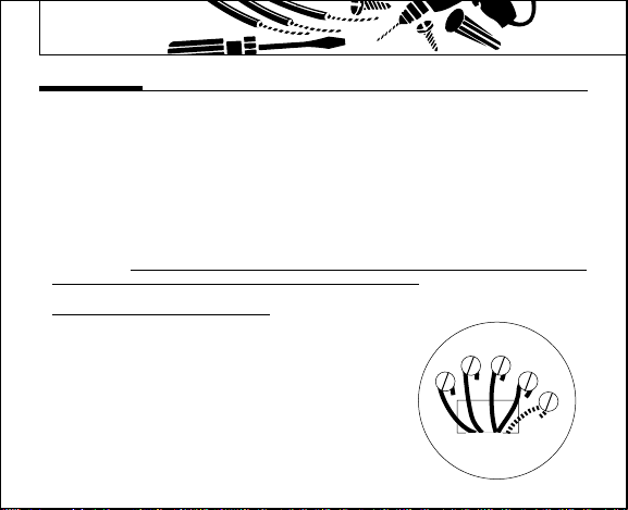
PROGRAMMING
3
You can practice programming before
installing your thermostat by inserting and
connecting the batteries and following the
instructions on page 14. This can be done while
you relax in your favorite chair and is a very
good way to familiarize yourself with all the
functions of your Hunter Thermostat.
OPERATION
4
Your Hunter Thermostat is designed to
operate with most gas, oil, electric or 2-wire
hot water heating, and air conditioning systems
that have 24-volt or millivolt control.
This Hunter Thermostat will not control multi-
stage heating or cooling systems, 11 /22 V
systems, or 3 wire zone systems.
COMPRESSOR PROTECTION
5
The thermostat provides a 4-minute delay
after shutting off the compressor before it
can be restarted. This feature will prevent
damage to your air conditioner compressor
caused by rapid cycling. It does not provide a
delay when there are power outages.
TEMPERAT RE RANGE
6
Your thermostat can be programmed between
4 °F and 95°F (5°C and 35°C). However, it will
display room temperatures from 32°F to 99°F ( °C
and 37°C).
POWER FAIL RE
7
Whenever the main power is interrupted or
fails, the battery power retains the programs
and current time.
AJ514/41253 book p. 1-15 2/8/01 3:16 PM Page 4