BBB Alfa HT1 User manual
Valve Tester
Alfa HT1
Instruction Manual
AF99999

VALVE TESTER ALFA HT1
AF99999
2
v2.0
Index
1. Safety precautions ...................................................................................................................3
2. Equipment cleaning .................................................................................................................4
3. Introduction ..............................................................................................................................5
4. Technical data ...........................................................................................................................6
5.
Equipment composition ..........................................................................................................7
6. Operation ..................................................................................................................................8
7. How to use ............................................................................................................................. 11
8. Test result .............................................................................................................................. 20
9.
System icons and Indicators.. ............................................................................................... 21
10. Troubleshooting ................................................................................................................. 22
11. Connectivity and updates ................................................................................................. 22
12. Guarantee ............................................................................................................................ 24
13. Rights Policy ........................................................................................................................ 25

3
v2.0
VALVE TESTER ALFA HT1
AF99999
1. Safety precautions
This product complies with the requirements of the following Directives and
Certifications of the European Community : 2014/35/EU of Low Voltage and
2014/30/EU of Electromagnetic compatibility.
•UNE EN 62368-1: 2020
•UNE – EN 61000-3-2:2019
•UNE – EN 61000-3-3:2013+A1:2020
•UNE-EN 55032:2016 +AC:2016-07 Class A
•UNE-EN 55035:2017+A11:2020
To ensure the proper functioning ofthe equipment and eliminate the danger ofdamage,
the following precautions must beobserved:
Damages caused by not respecting these safety precautions are exempt from any
legal claim, regardless of their nature.
•Before using the device, you must read, understand and follow this manual.
•Before connecting the device to the power supply, check that the mains voltage
corresponds to the voltage established for the equipment.
•Do not place the equipment ondamp orwet surfaces.
•Do not cover the ventilation slots of the equipment to ensure that air can
circulate freely inside.
•Do not insert metal objects into the device through the ventilation slots.
•Do not place containers with water on the device (risk of short circuit if the
container spills).
•This equipment should not beleft running unattended.
•Follow the instructions that appear on the equipment screen.
•Do not expose the equipment to direct sunlight or extreme temperatures, damp
or wet places.
•Do not expose the equipment to strong shocks or vibrations.
•Do not work with the equipment near strong magnetic fields (motors,
transformers, etc.).
•Keep hot electrodes orwelders away from the equipment.
•Regularly clean the equipment with a soft, dry cloth. Do not use abrasives or
solvents.
•The equipment is suitable for indoor use only.
•Do not store the equipment ina place close to explosives orflammable
substances.
•Do not modify the equipment in any way.
•Do not place the equipment upside down onany table orworkbench toprevent
any damage tothe screen fromthe front.
•During valve tests, do not touch the valves to avoid entrapment due to moving
parts.
•The equipment's disassembly and repair should exclusively be performed by
qualified technical personnel from the Alfa e-Parts team.
•The equipment should be stored beyond the access of children.

4
v2.0
VALVE TESTER ALFA HT1
AF99999
2. Equipment cleaning
Note: Before cleaning the equipment, remove the plug from the outlet.
To clean the equipment you must take into account the following considerations:
•Clean only with a soft, dry cloth.
•Do not use abrasive products or solvents.
•Plastic parts, cables and stand can be cleaned with a mild household cleaner.
•The use of liquid products could damage the equipment if they get inside it.
5
v2.0
VALVE TESTER ALFA HT1
AF99999
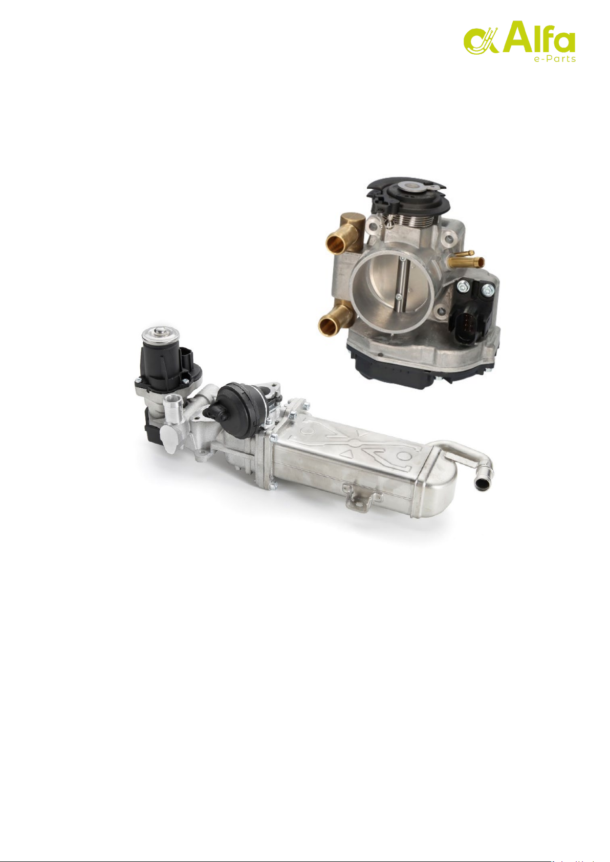
3. Introduction
The valve tester is designed to verify the correct operation of EGR valves and throttle
valves. Electrical drive units and units with position sensor(s) can be tested.
Its operation consists of making a series of activations on the valve motor and capturing
the response of the sensor (or sensors) to compare it with the expected signal. The
expected signal consists of a margin (tolerance).

6
v2.0
VALVE TESTER ALFA HT1
AF99999
4. Technical data
Operating Voltage 80 ~ 264 VCA – Conversion to 12VCC (5A)
Screen type Projected capacitive multi-touch
Screen Size 7”
Resolution1200 x 600 pixel
Operating system Ubuntu
Dimensions 270cm x 20cm x 8cm
Weight 3Kg
CPU 2GHz Quad-core 64 bits (Amlogic S905X3)
Internal memory 16 GB eMMC
Ethernet
Wifi Yes
1000 Mbps
v2.0
VALVE TESTER ALFA HT1
AF99999
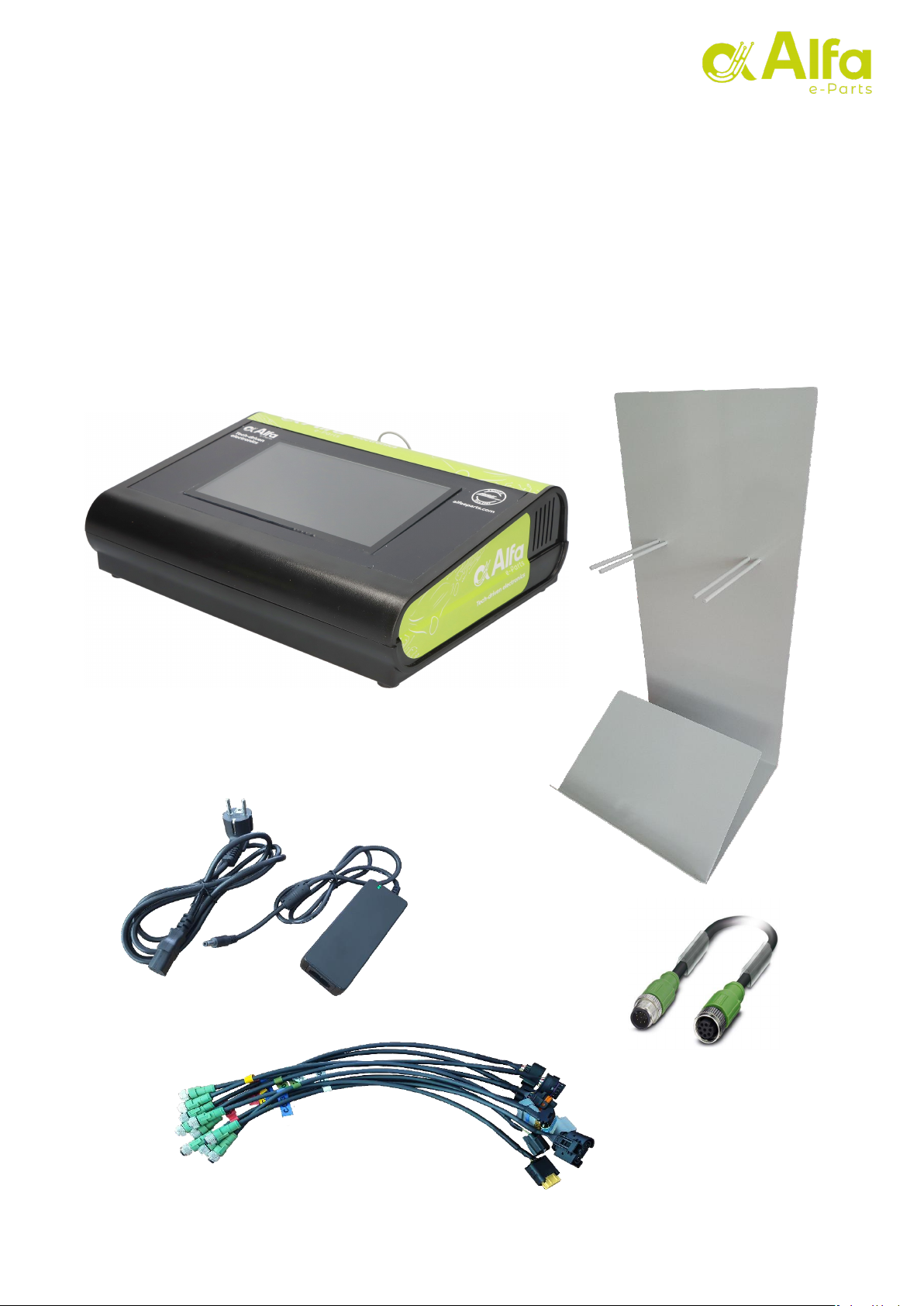
5. Equipment Composition
The equipment consists of the following elements:
•Touch screen tester
•Metallic support
•Tester power supply
•1.5 meter extension for test cables
•Test lead set
7
8
v2.0
VALVE TESTER ALFA HT1
AF99999
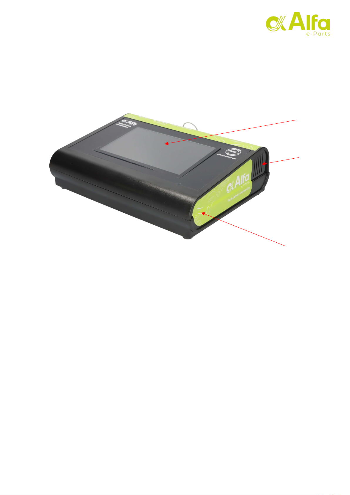
6. Operation
The tester consists of a plastic case and a touch screen that provides the control
interface for the operator.
1- Tester box
2- Touch screen
3- Ventilation grille
Note:
I
nthe sides of the box, wefind thetwoventilation grilles. It is important that these
are always uncovered to
prevent
overheating of the internal electronics ofthe tester.
2
1
3

VALVE TESTER ALFA HT1
AF99999
9
v2.0
At the back of the tester, all device connections and the main power switch are located.
1- Power connector
2- Network connector (RJ45)
3- Test cable connector
4- On/off switch
The equipment consists of a set of cables to adapt the tester to the different
connections incorporated by the valves to be tested. Each cable has a label located at
the end of the connector, indicating the identification number.
In addition, the equipment includes a 1.5m universal
extender to extend any of the cables that we must use.
1- Test lead set.
2- 1.5 meter extension cable for test cables.
3- Cable number identifier label.
1
2
3
1 2 3
4
VALVE TESTER ALFA HT1
AF99999
10
v2.0
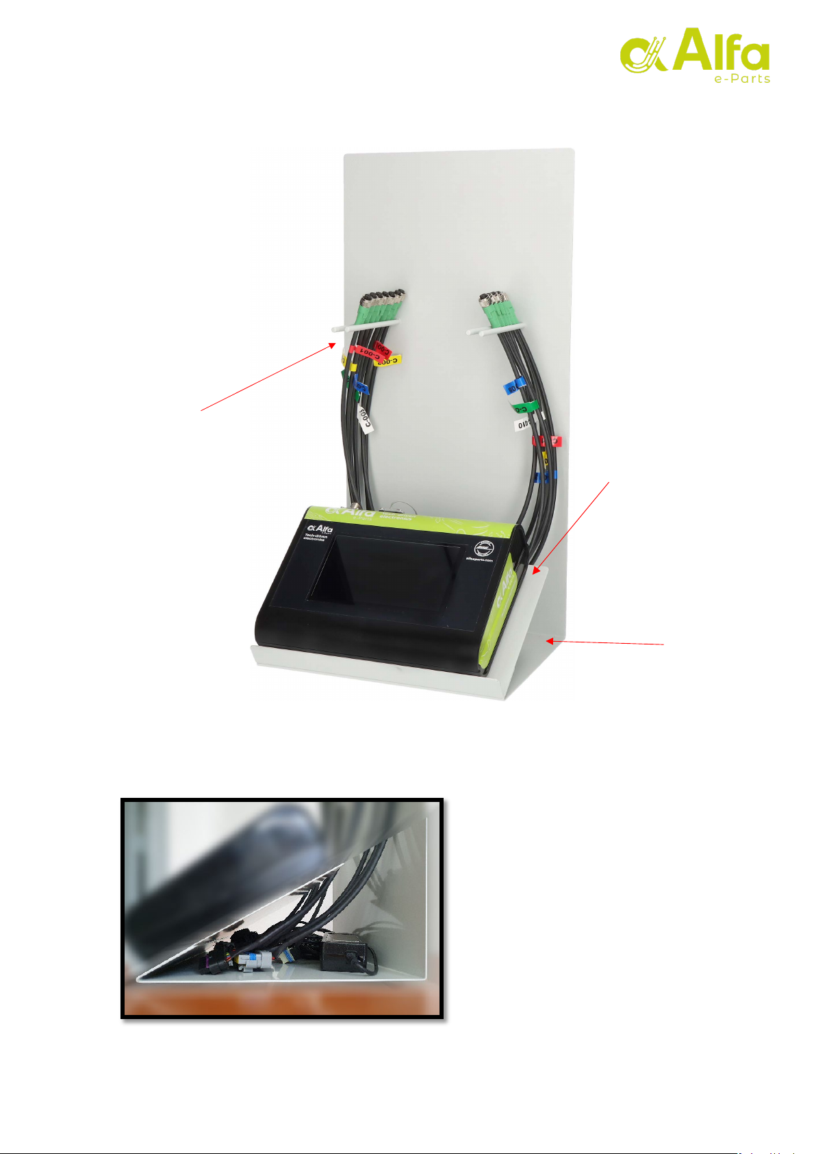
The equipment includes a metallic support for the placement of the tester with an
ergonomic inclination, and two supports for the storage of the cables.
1- Tester base.
2- Support for test cables.
3- Housing for the power supply.
Through the side of the support
access is provided for the end of
each cable and the power supply
1
2
3

11
v2.0
VALVE TESTER ALFA HT1
AF99999
7. How to use
1 – With the tester properly positioned, the power supply can be connected to a
suitable power outlet and to the tester device.
2 – Next, we can activate the switch on the rear side in the ON position.
3 – After viewing the startup progress bar, the screen will remain black for a few
seconds before displaying the screensaver.

12
v2.0
VALVE TESTER ALFA HT1
AF99999
4 – Click anywhere on the screen to exit the screensaver.
Note: The screen saver will automatically appear again if the machine is idle for more than
5 minutes.
5 – The first screen that we will see is the main menu. In this we can change the
language of the interface by pressing the corresponding flag in the upper right corner.
We select the type of device that we want to check (EGR or Throttle valve) using the
two buttons at the bottom.
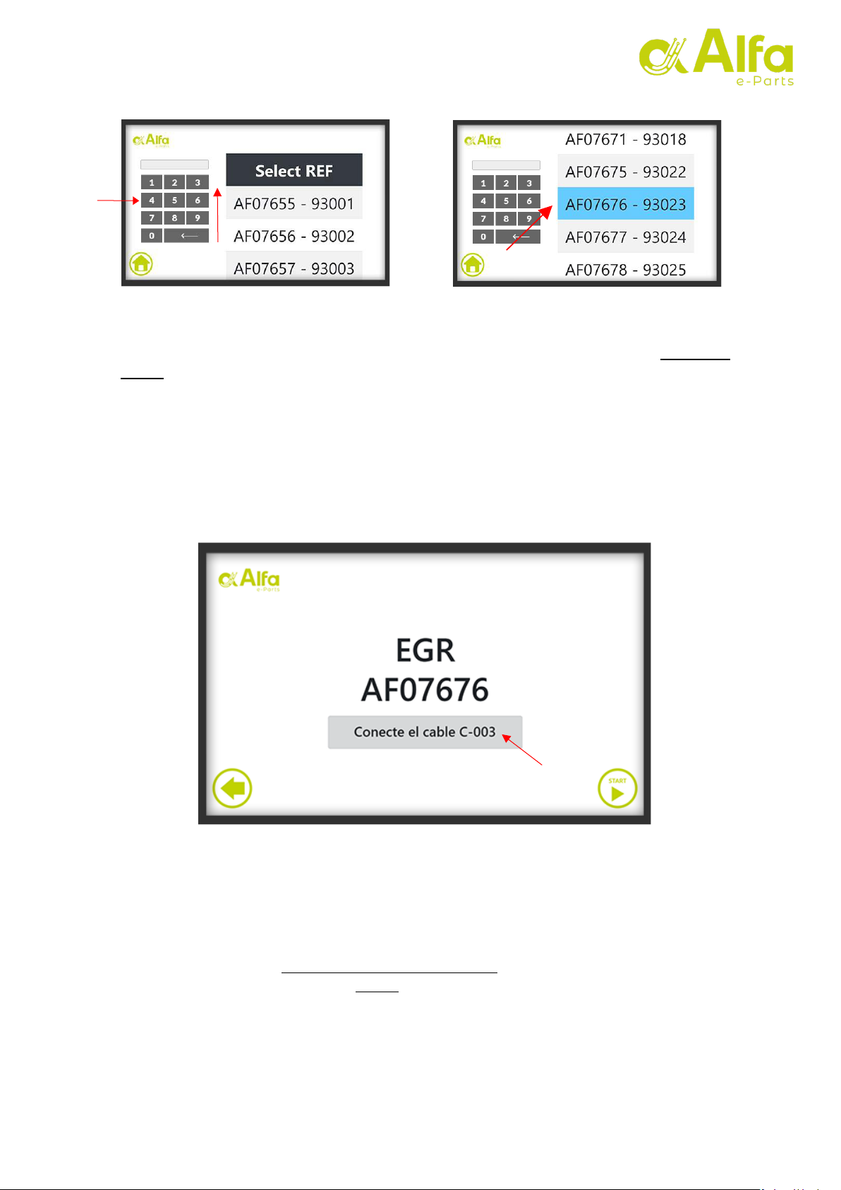
6 – After selecting the type of device we will access the part number selection screen.
We slide the list until we see the desired part number and clickon it, or use the numeric
keypad to search for the desired part number manually.
Press
Selection
Language
VALVE TESTER ALFA HT1
AF99999
13
v2.0
Note: The part number is found on the product box label and engraved on some surface of
the valve to be tested. In this example image we have selected the part number AF07676 -
93023.
7– On the next screen we can see the selected part number as confirmation. In this
interface, the cable number to be used for this device is indicated. Connect the
corresponding cable to the tester.
Note : Each of the included cables has a colored label with the cable number. The circular
connector of the tester has a precise mounting position: rotate the connector on the base
until it clicks, and screw the clamp gently.
Numeric
Keypad
14
v2.0
VALVE TESTER ALFA HT1
AF99999
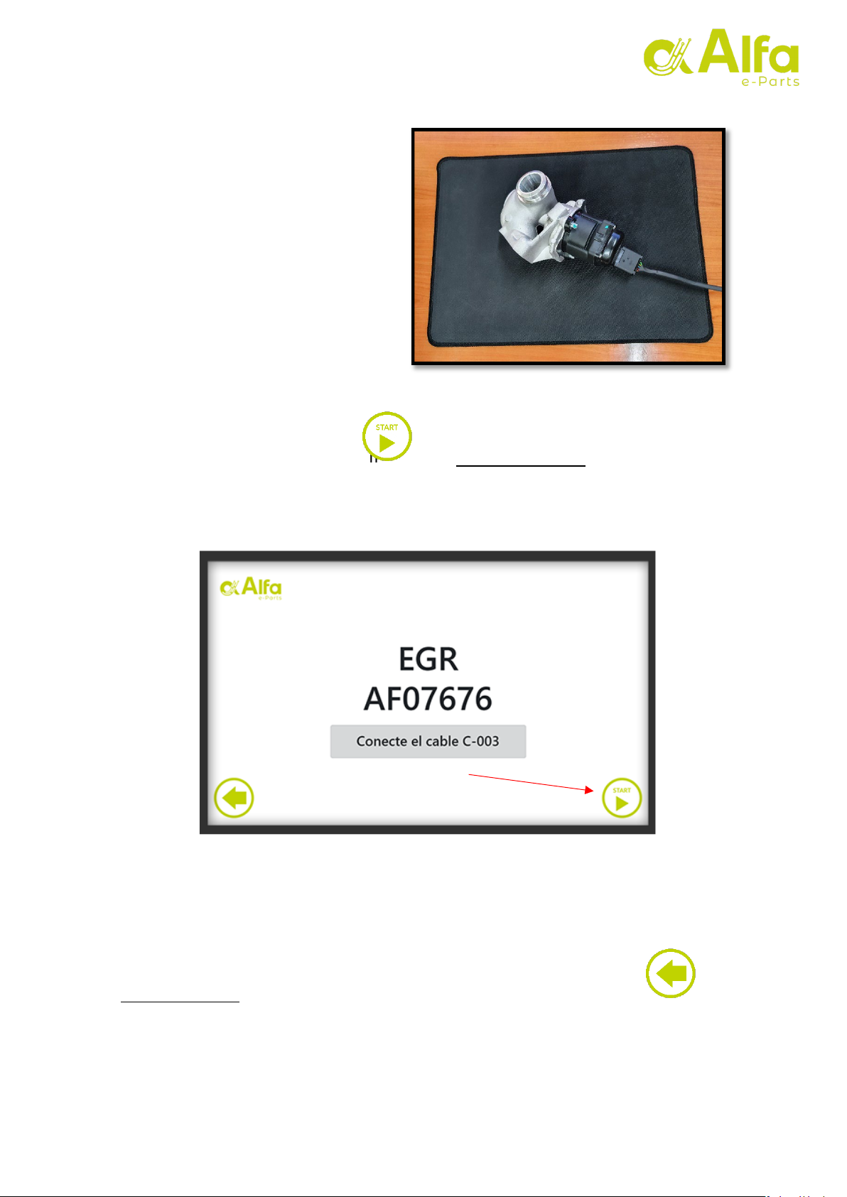
8–Place the valve to be tested in a
horizontal position on a soft surface
(cardboard, cork, expanded
polyethylene, etc.) and connect the
other end of the cable to it.
Note: It
'
simportant to connect the
cable carefully and not to force the
connector at any time, so as not to bend
or damage the valve pins or the
connector terminals.
To initiate the test,press the button in the lower right corner.
Note: If we have selected an incorrect part number we can press the button in the
lower left corner to return to the previous selection view.
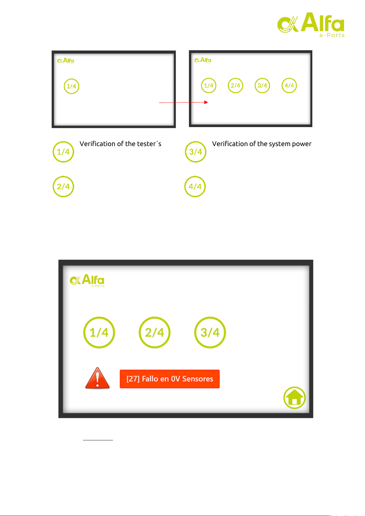
9 – Next, it can be observed 4 verification steps carried out by the tester.
VALVE TESTER ALFA HT1
AF99999
15
v2.0
Verification of the tester´s
electronic status.
Verification of the device
parameters recorded in the
database.
Verification of the system power
supplies (0V, 5V and 12V)
Verification of pin configuration,
detection of motor and sensors
If a fault is detected in any of the checks, the following alert will appear with the fault
number (in this example 27) and a brief description.
Note: See section 10 of this manual fordetailed information oneach fault.
10 – If all verifications are correct, the valve testing process is initiated.

VALVE TESTER ALFA HT1
AF99999
16
v2.0
In this phase, 4 activations will be carried out where the valve will move at
different speeds. Each activation lasts approximately ten seconds. Aprogress bar will
be visible for each of them with 4 states:
1. Green color: Activation has been completed successfully.
2. Red color: Activation is complete, but failures have been detected.
3. Gray color and moving: This activation is running.
Important note: During the activations, the
valve´s operation will be audible,
and it will
produce a vibration typical of the movement of the valve motor. These effects are
normal during the test. If the vibration of the valve produces a displacement of it on the
table, we must hold the soft surface on which we have placed the valve to
prevent it. Under no circumstances should we touch the valve when it is in
operation (it has moving parts and could cause crushing injuries).
1 23
VALVE TESTER ALFA HT1
AF99999
17
v2.0
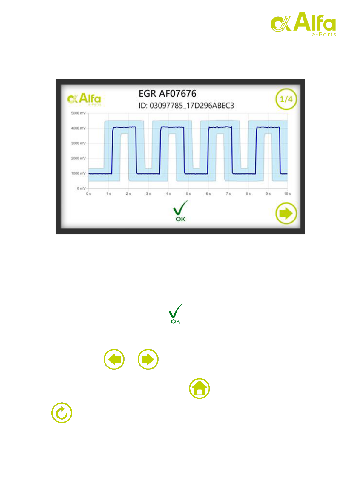
11 – After the activations are completed, and after a few seconds of processing, the
graph viewer located onthe first ofthe four pages will be displayed.
At the top we can see valve information formed by EGR or THR (throttle valve) followed
by the part number. Just below we find the unique identifier of the test. In the upper
right corner we can see what page we are on.
In the example we can see that the tested device is an EGR with part number AF07676 and
that the test identifier is 03097785_17D296ABEC3.
At the bottom we will see the icon indicating that, in this activation of the
example, the test has been successful. This means that the signal has not gone outside
the limits defined by the tolerance at any time.
With the buttons and we can move between the four graphs.
On the last page (4/4) there will be a button to return to the initial menu and
to repeat the test on the same valve.
VALVE TESTER ALFA HT1
AF99999
18
v2.0
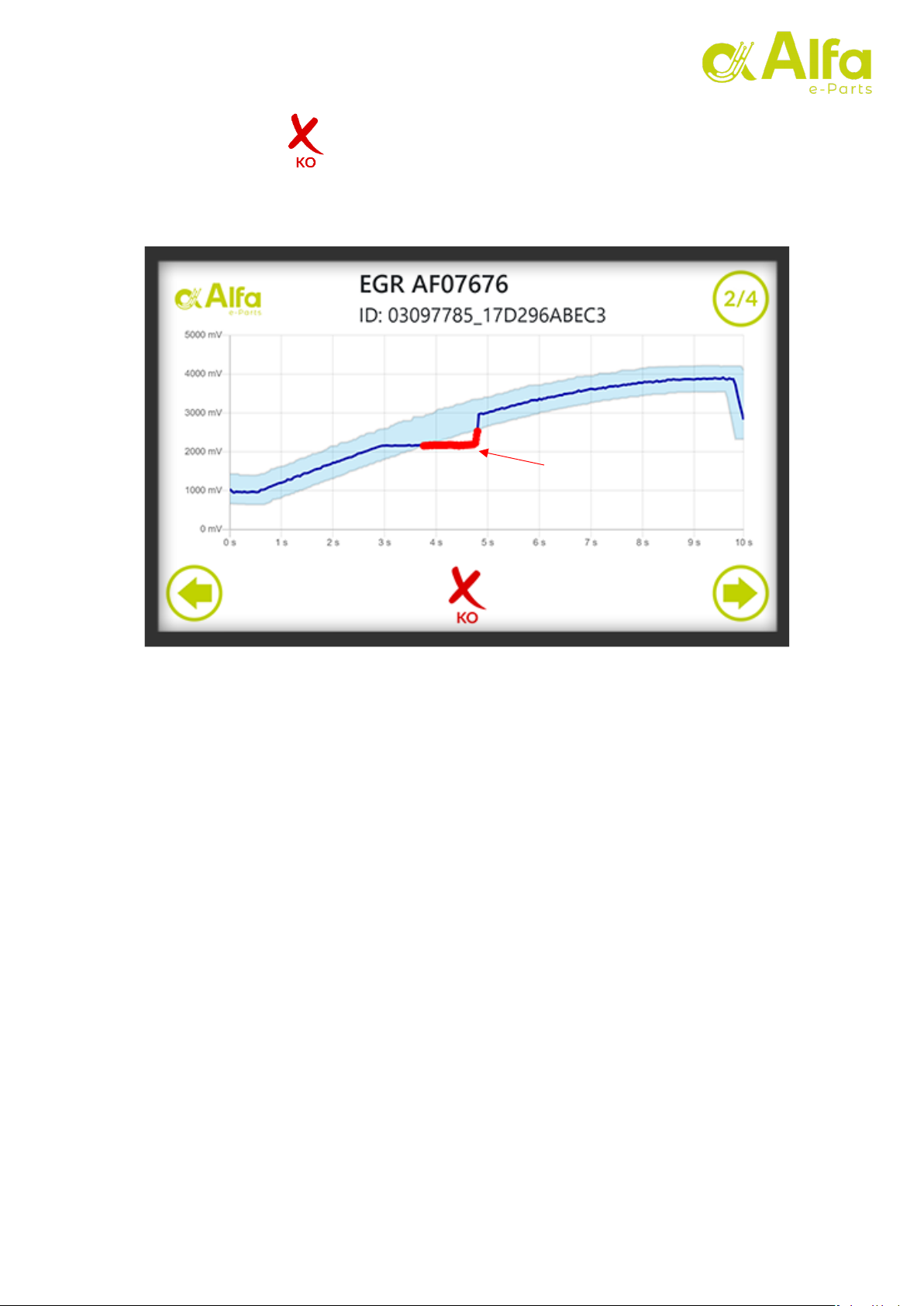
is displayed at the bottom, indicating that the verification
In the second test,
did not pass successfully.
This means that the signal has gone beyond the limits set by the tolerance at some
point during the activation, as we can see in the example.
Note: If a signal has produced a fault, all points of the signal that are out of tolerance
during activation will be marked in red.
Failures
VALVE TESTER ALFA HT1
AF99999
19
v2.0
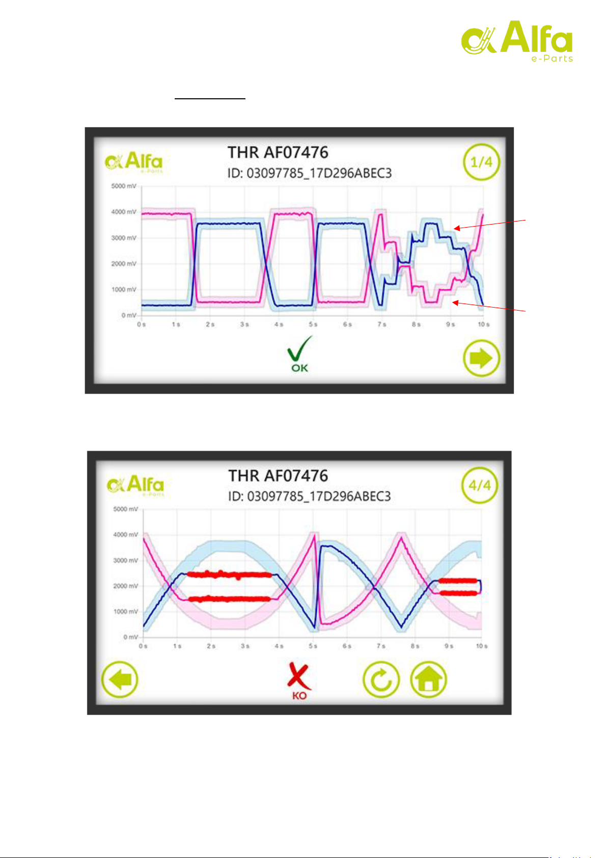
Some throttle valves have a second sensor. In this case, the secondary sensor will
be displayed in a magenta tone (both signal and tolerance).
Sensor 2
Sensor 1

20
v2.0
VALVE TESTER ALFA HT1
AF99999
8. Test result
The favorable result of the tests implies that the tested valve is within the specifications
and operating tolerances approved by the manufacturer and the quality control of Alfa
e-Parts.
An unfavorable test result indicates that the operation of the testedvalve exceeds the
limits set for its correct operation.
In the event that the valve tested with an unfavorable result is within the stipulated
warranty period, it must be sent to Alfa e-Parts, together with the ID of the test, for
examination in the laboratory and to determine the cause of its failure. For this process,
you must follow the guarantee protocol established by Alfa e-Parts.
Any manipulation, modification or foreign body found in the valve will cause the loss of
the guarantee and will be returned toits sender.
Before turning off the tester:
Once the verification is finished, if the machine is connected to the internet, we must
wait a few seconds before stopping it so that it can correctly send the captured
data. During this time,we can take the opportunity to disconnect the adapter cable
from the valve and from the tester.
Note: It is important to disconnect the connectors with caution.You should always pull on
the connector, never on the cable. Otherwise
the wiring could be damaged.
Table of contents


