BEAMEX FB150 User manual

FBXXX___tgeng0000
Field Temperature Block series
Beamex® FB150, FB350, FB660
User Guide

FBXXX Field Temperature Block
ii

iii
Table of Contents
1 Before You Start .......................................................................1
1.1 Introduction ............................................................................................... 1
1.2 Unpacking ................................................................................................ 2
1.3 Symbols Used ........................................................................................... 3
1.4 Safety Information ..................................................................................... 4
1.4.1 Warnings .........................................................................................................4
1.4.2 Cautions ..........................................................................................................6
1.5 CE Comments ........................................................................................... 7
1.5.1 EMC Directive .................................................................................................7
1.5.2 Immunity Testing .............................................................................................8
1.5.3 Emission Testing ..............................................................................................8
1.5.4 Low Voltage Directive (Safety) ........................................................................8
1.6 Authorized Service Centers ...................................................................... 9
2 Specications and Environmental Conditions .................... 11
2.1 Specifications ......................................................................................... 11
2.2 Environmental Conditions ....................................................................... 12
3 Quick Start ..............................................................................13
3.1 Setup ....................................................................................................... 13
3.2 Parts and Controls .................................................................................. 14
3.2.1 Display Panel ................................................................................................15
3.2.2 Display ..........................................................................................................16
3.2.3 Power Panel ..................................................................................................17
3.2.4 -R Option Panel (-R models only) ..................................................................20
3.3 Languages .............................................................................................. 21
3.3.1 Language Selection ......................................................................................22
3.3.2 Reset to English Language ...........................................................................22
4 Menu Structure .......................................................................23
4.1 Temp Setup Menu ................................................................................... 23
4.2 Prog Menu .............................................................................................. 24
4.3 System Menu .......................................................................................... 25
4.4 Input Setup (-R only) ............................................................................... 26
5 Controller operation...............................................................27

FBXXX Field Temperature Block
iv
5.1 Main Screen ............................................................................................ 27
5.2 Main Menu .............................................................................................. 28
5.2.1 Temp Setup ...................................................................................................28
5.2.2 Prog Menu .....................................................................................................30
5.2.3 System Menu .................................................................................................32
5.2.4 INPUT SETUP (-R model only) ......................................................................38
6 Digital communication interface...........................................43
6.1 Wiring ...................................................................................................... 43
6.1.1 Setup .............................................................................................................43
6.1.2 Serial Operation ............................................................................................43
6.2 Command Syntax ................................................................................... 44
6.3 Commands by Function or Group .......................................................... 45
6.4 Serial Commands - Alphabetic Listing ................................................... 48
6.5 Non-SCPI Process Commands ............................................................... 66
6.6 Non-SCPI Commands by Function or Group ......................................... 66
7 Troubleshooting .....................................................................69
8 Maintenance ...........................................................................71
8.1 Field Temperature Block Performance Analysis ..................................... 71

v
Tables
Table 1 Symbols used ........................................................................................ 3
Table 2 Base Unit Specifications ..................................................................... 11
Table 3 -R Option Specifications .................................................................... 12
Table 4 Matching Certificate Values to ITS-90 Coefficients ............................. 39
Table 5 Setting Coefficients Rtpw, a8, b8, and b4 ........................................... 39
Table 6 Commands by Function or Group ....................................................... 45
Table 7 PROG:SEQ:PAR parameters ............................................................... 55
Table 8 Troubleshooting, problems, causes and solutions .............................. 69

FBXXX Field Temperature Block
vi
Figures
Figure 1 Clamp-on ferrite installation ................................................................ 8
Figure 2 FBXXX Field Temperature Block ........................................................ 14
Figure 3 Display panel and keys ..................................................................... 16
Figure 4 FBXXX display ................................................................................... 17
Figure 5 FB150 power panel ........................................................................... 19
Figure 6 FB350 and FB660 power panel ......................................................... 19
Figure 7 -R option panel ................................................................................. 20
Figure 8 Probe connector wiring ..................................................................... 21
Figure 9 Steps to language selection .............................................................. 22
Figure 10 Main Menu - Temp SetUp ................................................................ 23
Figure 11 Main Menu - Prog Menu .................................................................. 24
Figure 12 Main Menu - System Menu .............................................................. 25
Figure 13 Main Menu - Input Setup ................................................................ 26
Figure 14 RS-232 wiring .................................................................................. 44

1
Before You Start
Introduction
1 Before You Start
1.1 Introduction
Field Temperature Blocks (FB150, FB350, and FB660) are designed to be reliable,
stable heat sources that can be used in the eld or laboratory. They offer accuracy,
portability, and speed for nearly every eld calibration application. The instruments
have been designed with the eld user in mind and are easy to use while maintaining
stability, uniformity, and accuracy comparable to some laboratory instruments.
Special built-in features make Field Temperature Blocks extremely adaptable. The
exclusive Voltage Compensation allows the technician to plug into mains power with
voltage from 90 V ac to 250 V ac without degradation to the instrument. The Ambient
Temperature Compensation provides the largest operating range in the industry (0°C
to 50°C) with the largest guaranteed temperature range (13°C to 33°C). The Gradi-
ent Temperature Compensation keeps the axial gradient within specication over the
entire temperature range of the instrument and over the specied guaranteed operat-
ing temperature range. These combined features along with the rugged design, light
weight, and small size make this line of instruments ideal for eld applications.
Unique Patent Pending safety features make these the safest eld heat sources avail-
able. The unique Air Flow Design keeps the probe handle cool protecting delicate
instruments and the user. The Block Temperature Indicator shows the user when the
well temperature is above 50°C letting the user know when it is safe to remove the
insert or move the instrument. The indicator light illuminates when the instrument is
energized and the well is above 50°C. If the instrument is removed from mains power,
the indicator light ashes until the well has cooled to less than 50°C.
The optional “-R” version (“FBXXX-R”) combines the heat source with a built-in
reference.
The Field Temperature Blocks’ controller uses a PRT sensor and thermoelectric mod-
ules or heaters to achieve stable, uniform temperatures throughout the block.
The LCD display continuously shows many useful operating parameters including the
block temperature, the current set-point, block stability, and heating and cooling status.
For the -R version, the reference temperature readings are displayed. The display can
be set to show the information in one of eight different languages; English, Japanese,
Chinese, German, Spanish, French, Russian, and Italian.
The instrument’s rugged design and special features make them ideal for the eld or
the laboratory. With proper use, the instrument provides continued accurate calibration
of temperature sensors and devices. Before use, the user should be familiar with the
warnings, cautions, and operating procedures of the block as described in the User’s
Guide.

FBXXX Field Temperature Blocks
Unpacking
2
1.2 Unpacking
Unpack the instrument carefully and inspect it for any damage that may have occurred
during shipment. If there is shipping damage, notify the carrier immediately.
Verify that the following components are present:
FB150
FB150 Field Temperature Block
Insert: FB150-MH2, FB150-MH1, or FB150-B
Power Cord
RS-232 Cable
User Guide
Calibration Certicate and calibration label
LEMO Connector (-R model only)
Well Insulator
Clamp-on ferrites (3) [-R model only]
Tongs (insert removal tool)
FB350
FB350 Field Temperature Block
Insert: FB350-MH2, FB350-MH1, or FB350-B
Power Cord
RS-232 Cable
User Guide
Calibration Certicate and calibration label
LEMO Connector (-R model only)
Clamp-on ferrites (3) (-R model only)
Tongs (insert removal tool)
FB660
FB660 Field Temperature Block
Insert: FB660-MH2, FB660-MH1, or FB660-B
Power Cord
RS-232 Cable
User Guide
Calibration Certicate and calibration label
LEMO Connector (-R model only)
Clamp-on ferrites (3) [-R model only]
Tongs (insert removal tool)
3
Before You Start
Symbols Used
If all items are not present, contact an Authorized Service Center (see Section 1.6Au-
thorized Service Centers on page 9).
1.3 Symbols Used
Table 1 lists the International Electrical Symbols. Some or all of these symbols may be
used on the instrument or in this guide.
Table 1 Symbols used
Symbol Description
AC (Alternating Current)
AC-DC
Battery
Complies with European Union directives
DC
Double Insulated
Electric Shock
Fuse
PE Ground
Hot Surface (Burn Hazard)
FBXXX Field Temperature Blocks
Safety Information
4
Symbol Description
Read the User’s Guide (Important Information)
Off
On
Canadian Standards Association
C-TICK Australian EMC mark
The European Waste Electrical and Electronic Equipment (WEEE) Directive (2002/96/
EC) mark.
1.4 Safety Information
Field Temperature Blocks are designed in accordance with IEC 61010-1, IEC 61010-
2-010 and CAN/CSA 22.2 No 61010.1-04. Use this instrument only as specied in this
manual. Otherwise, the protection provided by the instrument may be impaired. Refer
to the safety information in the Warnings and Cautions sections below.
The following denitions apply to the terms “Warning” and “Caution”.
“Warning” identies conditions and actions that may pose hazards to the user.
“Caution” identies conditions and actions that may damage the instrument
being used.
1.4.1 Warnings
To avoid personal injury, follow these guidelines.
GENERAL
DO NOT use this instrument in environments other than those listed in the User’s
Guide.
Inspect the instrument for damage before each use. Inspect the case. Look for cracks
or missing plastic. DO NOT use the instrument if it appears damaged or operates
abnormally.

5
Before You Start
Safety Information
Follow all safety guidelines listed in the User’s Guide.
Calibration equipment should only be used by trained personnel.
If this equipment is used in a manner not specied by the manufacturer, the protection
provided by the equipment may be impaired.
Before initial use, or after transport, or after storage in humid or semi-humid environ-
ments, or anytime the instrument has not been energized for more than 10 days, the
instrument needs to be energized for a “dry-out” period of 2 hours before it can be
assumed to meet all of the safety requirements of the IEC 1010-2. If the product is wet
or has been in a wet environment, take necessary measures to remove moisture prior
to applying power such as storage in a low humidity temperature chamber operating at
50°C for 4 hours or more.
DO NOT use this instrument for any application other than calibration work. The
instrument was designed for temperature calibration. Any other use of the instrument
may cause unknown hazards to the user.
DO NOT place the instrument under a cabinet or other structure. Overhead clearance
is required. Always leave enough clearance to allow for safe and easy insertion and
removal of probes.
Use of this instrument at HIGH TEMPERATURES for extended periods of time
requires caution.
Completely unattended high temperature operation is not recommended due to safety
hazards that can arise.
This instrument is intended for indoor use only.
Follow all safety procedures for the test and calibration equipment you use.
Do not use the instrument if it operates abnormally. Protection may be impaired. When
in doubt, have the instrument serviced.
DO NOT operate the Field Temperature Block around explosive gas, vapor, or dust.
DO NOT operate instrument at orientations other than upright. Tilting the instrument
or laying it down on its side during use could create a re hazard.
BURN HAZARD
The instrument is equipped with a Block Temperature Indicator (front panel LED
HOT indicator) even when the instrument is unplugged. When the indicator is ash-
ing, the instrument is disconnected from mains power and the temperature of the block
is above 50°C. When the indicator is illuminated, always on, the instrument is pow-
ered and the block temperature is above 50°C.
DO NOT turn the instrument upside down with the inserts in place; the inserts will
fall out.
DO NOT operate near ammable materials.

FBXXX Field Temperature Blocks
Safety Information
6
Use of this instrument at HIGH TEMPERATURES for extended periods of time
requires caution.
DO NOT touch the well access surface of the instrument.
The block vent may be very hot due to the fan blowing across the heater block of the
instrument.
The temperature of the well access is the same as the actual display temperature, e.g. if
the instrument is set to 600°C and the display reads 600°C, the well is at 600°C.
Probes and inserts may be hot and should only be inserted and removed from the
instrument when the instrument indicates temperatures less than 50°C.
DO NOT turn off the instrument at temperatures higher than 100°C. This could create
a hazardous situation. Select a set-point less than 100°C and allow the instrument to
cool before turning it off.
The high temperatures present in Field Temperature Blocks designed for operation
at 300°C and higher may result in res and severe burns if safety precautions are not
observed.
ELECTRICAL HAZARD
These guidelines must be followed to ensure that the safety mechanisms in this instru-
ment operate properly. This instrument must be plugged into an AC only electric outlet
according to Table 2, Specications . The power cord of the instrument is equipped
with a grounding plug for your protection against electrical shock hazards. It must be
plugged directly into a properly grounded receptacle. The receptacle must be installed
in accordance with local codes and ordinances. Consult a qualied electrician. DO
NOT use an extension cord or adapter plug.
If supplied with user accessible fuses, always replace the fuse with one of the same
rating, voltage, and type.
Always replace the power cord with an approved cord of the correct rating and type.
HIGH VOLTAGE is used in the operation of this equipment. SEVERE INJURY or
DEATH may result if personnel fail to observe safety precautions. Before working
inside the equipment, turn power off and disconnect power cord.
1.4.2 Cautions
To avoid possible damage to the instrument, follow these guidelines:
DO NOT leave the inserts in the instrument for prolonged periods. Due to the high
operating temperatures of the instrument, the inserts should be removed after each use
and buffed with a Scotch-Brite® pad or emery cloth (see Section 8Maintenance on
page 71).
Always operate this instrument at room temperature between 5°C and 50°C (41°F to
122°F). Allow sufcient air circulation by leaving at least 15 cm (6 in) of clearance

7
Before You Start
CE Comments
around the instrument. Overhead clearance of 1 meter (3 ft) is required. DO NOT
place instrument under any structure.
Component lifetime can be shortened by continuous high temperature operation.
DO NOT use uids to clean out the well. Fluids could leak into electronics and dam-
age the instrument.
Never introduce any foreign material into the probe hole of the insert. Fluids, etc. can
leak into the instrument causing damage.
Unless recalibrating the instrument DO NOT change the values of the calibration con-
stants from the factory set values. The correct setting of these parameters is important
to the safety and proper operation of the block.
DO NOT allow the probe sheath or inserts to drop into the well. This type of action
can cause a shock to the sensor and affect the calibration.
The instrument and any thermometer probes used with it are sensitive instruments that
can be easily damaged. Always handle these devices with care. DO NOT allow them
to be dropped, struck, stressed, or overheated.
DO NOT operate this instrument in an excessively wet, oily, dusty, or dirty environ-
ment. Always keep the well and inserts clean and clear of foreign material.
The Field Temperature Block is a precision instrument. Although it has been designed
for optimum durability and trouble free operation, it must be handled with care. Al-
ways carry the instrument in an upright position to prevent the inserts from dropping
out. The convenient handle allows for hand carrying the instrument.
If a mains supply power uctuation occurs, immediately turn off the instrument.
Power bumps from brown-outs could damage the instrument. Wait until the power has
stabilized before re-energizing the instrument.
The probe and the block may expand at different rates. Allow for probe expansion
inside the well as the block heats. Otherwise, the probe may become stuck in the well.
Most probes have handle temperature limits. If the probe handle limits are exceeded,
the probe may be permanently damaged. Due to a unique Air Flow Design, Field Tem-
perature Blocks protect the probe handle temperature and provide a safer temperature
handle for the user.
1.5 CE Comments
1.5.1 EMC Directive
Beamex equipment has been tested to meet the European Electromagnetic Compatibil-
ity Directive (EMC Directive, 89/336/EEC). The Declaration of Conformity for your
instrument lists the specic standards to which the instrument was tested.
FBXXX Field Temperature Blocks
CE Comments
8
The instrument was designed specically as a test and measuring device. Compliance
to the EMC directive is through IEC 61326-1 Electrical equipment for measurement,
control and laboratory use.
As noted in the IEC 61326-1, the instrument can have varying congurations. The
instrument was tested in a typical conguration with shielded RS-232 cables.
1.5.2 Immunity Testing
Using Clamp-On Ferrites
For the –R model only, clamp-on ferrites are provided for use in improving its electro-
magnetic (EM) immunity in environments of excessive EM interference. During EMC
testing we found that ferrites clamped around probe cables for the Reference PRT in-
put reduced the risk the EM interference affects measurements. Therefore, we recom-
mend that the clamp-on ferrites provided be used on the cables of probes attached to
the readout, especially if the product is used near sources of EM interference such as
heavy industrial equipment.
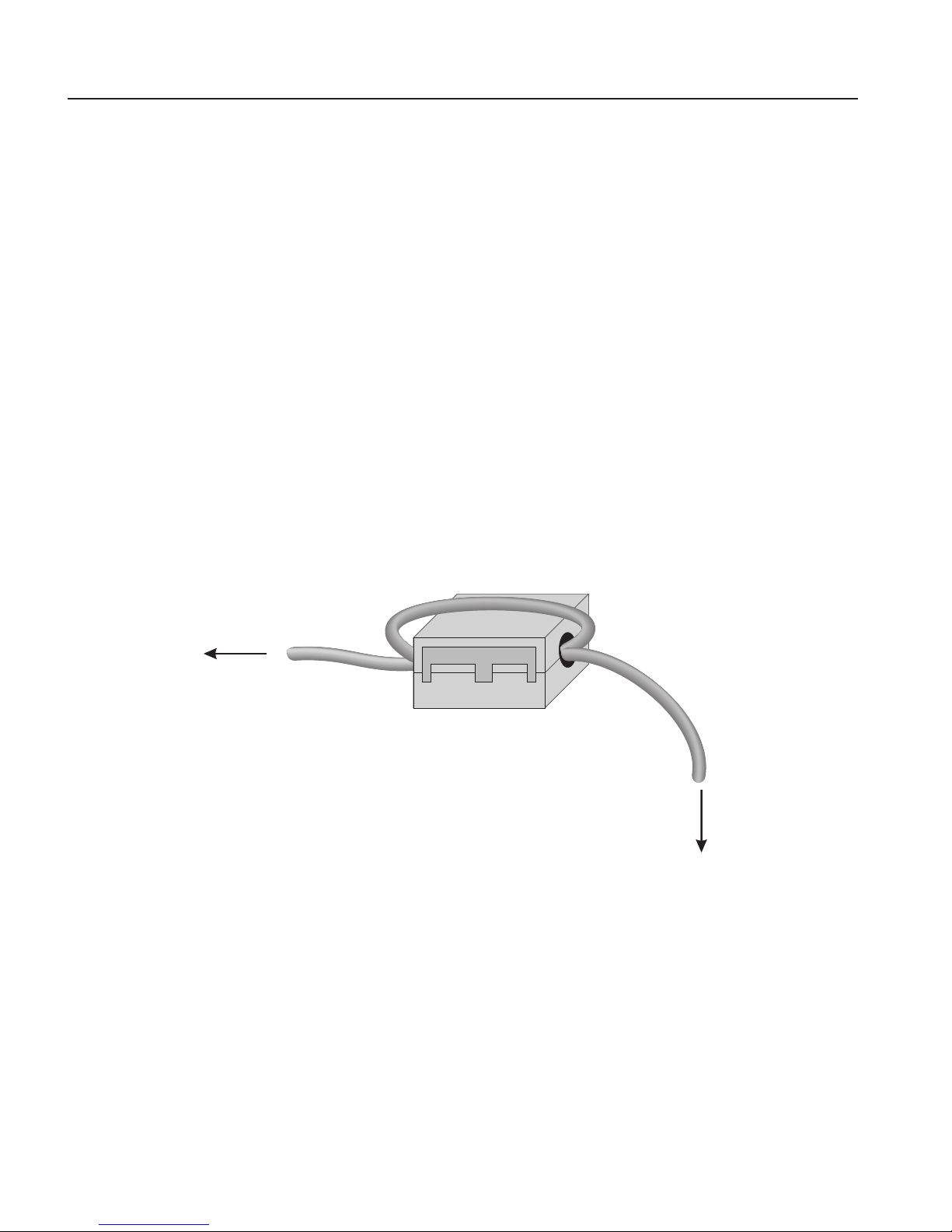
To attach a ferrite to a probe cable, make a loop in the cable near the connector and
clamp the ferrite around half of the loop as shown in the diagram. The ferrite can be
easily snapped open and moved to a new probe when needed.
Figure 1
clamp-on ferrite
connector
probe
Clamp-on ferrite installation
1.5.3 Emission Testing
The instrument fullls the limit requirements for Class A equipment. The instrument
was not designed to be used in domestic establishments.
1.5.4 Low Voltage Directive (Safety)
In order to comply with the European Low Voltage Directive (2006/95/EC), Bea-
mex equipment has been designed to meet the EN 61010-1 and the EN 61010-2-010
standards.

9
Before You Start
Authorized Service Centers
1.6 Authorized Service Centers
Please contact the following Authorized Service Center to coordinate service on your
Beamex product:
Beamex Oy Ab
Ristisuonraitti 10
FI-68600 Pietarsaari
Finland
When contacting a Service Centers for support, please have the following information
available:
Model Number
Serial Number
Voltage
Complete description of the problem


11
Specications and Environmental Conditions
Specications
2 Specications and Environmental Conditions
2.1 Specications
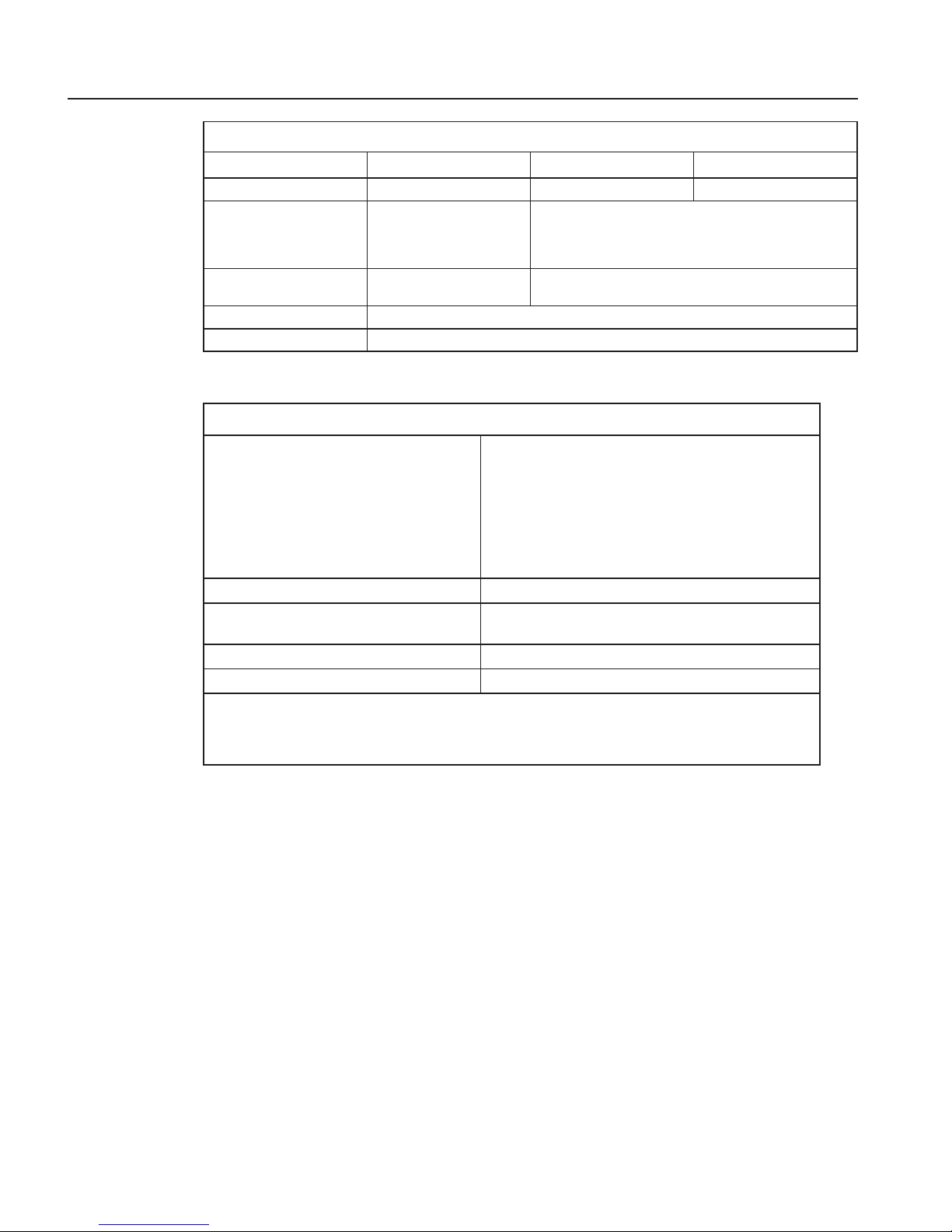
Table 2 Base Unit Specifications
Base Unit Specifications
FB150 FB350 FB660
Temperature Range at
23°C
–25°C to 150°C
(-13°F to 302°F)
33°C to 350°C
(91°F to 662°F)
50°C to 660°C
(122°F to 1220°F)
Display Accuracy ±0.2°C Full Range ±0.2°C Full Range ±0.35°C at 50°C
±0.35°C at 420°C
±0.5°C at 660°C
Stability ±0.01°C Full Range ±0.02 °C at 33°C
±0.02 °C at 200°C
±0.03°C at 350°C
±0.03°C at 50°C
±0.05°C at 420°C
±0.05°C at 660°C
Axial Uniformity at 40
mm (1.6 in)
±0.05°C Full Range ±0.04°C at 33°C
±0.1°C at 200°C
±0.2°C at 350°C
±0.05°C at 50°C
±0.35°C at 420°C
±0.5°C at 660°C
Axial Uniformity at 60
mm (2.4 in)
±0.07°C Full Range ±0.04°C at 33°C
±0.2°C at 200°C
±0.25°C at 350°C
±0.1°C at 50°C
±0.6°C at 420°C
±0.8°C at 660°C
Radial Uniformity ±0.01°C Full Range ±0.01°C at 33°C
±0.015°C at 200°C
±0.02°C at 350°C
±0.02°C at 50°C
±0.05°C at 420°C
±0.1°C at 660°C
Loading Effect (with
a 6.35 mm reference
probe and three 6.35
mm probes)
±0.006°C Full Range ±0.015°C Full Range ±0.015°C at 50°C
±0.025°C at 420°C
±0.035°C at 660°C
Loading Effect (versus
display with 6.35 mm
probes)
±0.08°C Full Range ±0.2°C Full Range ±0.1°C at 50°C
±0.2°C at 420°C
±0.2°C at 660°C
Hysteresis 0.025°C 0.06°C 0.2°C
Operating Conditions 0°C to 50°C, 0% to 90% RH (non-condensing)
Environmental
conditions for all
specications except
temperature range
13°C to 33°C
Immersion (Well) Depth 150 mm (5.9 in)
Insert OD 30 mm (1.18 in) 25.3 mm (1.00 in) 24.4 mm (0.96 in)
Heating Time 16 min: 23°C to 140°C
23 min: 23°C to 150°C
25 min: –25°C to 150°C
5 min: 33°C to 350°C 15 min: 50°C to 660°C
Cooling Time 15 min: 23°C to –25°C
25 min: 150°C to –23°C
32 min: 350°C to 33°C
14 min: 350°C to 100°C
35 min: 660°C to 50°C
25 min: 660°C to 100°C
Resolution 0.01°
Display LCD,°C or°F user-selectable
Key Pad Arrows, Menu, Enter, Exit, 4 soft keys
Size (H x W x D) 290 mm x 185 mm x 295 mm (11.4 x 7.3 x 11.6 in)
FBXXX Field Temperature Block
Environmental Conditions
12
Base Unit Specifications
FB150 FB350 FB660
Weight 8.16 kg (18 lbs) 7.3 kg (16 lbs) 7.7 kg (17 lbs)
Power Requirements 100 V to 115 V (±10%)
50/60 Hz, 575 W
230 V (±10%) 50/60 Hz,
575 W
100 V to 115 V (±10%), 50/60 Hz, 1400 W
230 V (±10%), 50/60 Hz, 1800 W
System Fuse Ratings 115 V: 6.3 A T 250 V
230 V: 3.15 A T 250 V
15 A, 250 V Thermal Circuit Breakers
Computer Interface RS-232
Safety EN 61010-1:2001, CAN/CSA C22.2 No. 61010.1-04
Table 3 -R Option Specifications
-R Specifications
Built-in Reference Thermometer Readout
Accuracy
(4-Wire Reference Probe)†
± 0.013 °C at -25 °C
± 0.015 °C at 0 °C
± 0.020 °C at 50 °C
± 0.025 °C at 150 °C
± 0.030 °C at 200 °C
± 0.040 °C at 350 °C
± 0.050 °C at 420 °C
± 0.070 °C at 660 °C
Reference Resistance Range 0 ohms to 400 ohms
Reference Resistance Accuracy‡ 0 ohms to 42 ohms: ±0.0025 ohms
42 ohms to 400 ohms: ±60 ppm of reading
Reference Characterizations ITS-90, CVD, IEC-60751, Resistance
Reference Measurement Capability 4-wire
†The temperature range may be limited by the reference probe connected to the readout. The Built-
In Reference Accuracy does not include the sensor probe accuracy. It does not include the probe
uncertainty or probe characterization errors.
‡Measurement accuracy specications apply within the operating range and assume 4-wires for PRTs.
2.2 Environmental Conditions
Although the instrument has been designed for optimum durability and trouble-free
operation, it must be handled with care. The instrument should not be operated in an
excessively dusty or dirty environment. Maintenance and cleaning recommendations
can be found in the Maintenance section. The instrument operates safely under the fol-
lowing environmental conditions:
ambient temperature range: 0-50°C (32-122°F)
ambient relative humidity: 0 % to 90 % (non-condensing)
mains voltage: within ±10% of nominal
vibrations in the calibration environment should be minimized
altitude: less than 2,000 meters
indoor use only

13
Quick Start
Setup
3 Quick Start
3.1 Setup
Note: The instrument will not heat, cool, or control until the “SET PT.”
parameter is “Enabled”.
Place the block on a at surface with at least 15 cm (6 in) of free space around the in-
strument. Overhead clearance is required. DO NOT place under a cabinet or structure.
Plug the instrument power cord into a mains outlet of the proper voltage, frequency,
and current capability (see Section 2.1, Specications, on page 11 for power details).
Observe that the nominal voltage corresponds to that indicated on the front of the
block.
Carefully place the insert into the well. Inserts should be of the smallest hole diam-
eter possible still allowing the probe to slide in and out easily. Various insert sizes
are available. Contact an Authorized Service Center for assistance (see Section 1.6,
Authorized Service Centers, on page 9). The well must be clear of any foreign objects,
dirt and grit before an insert is installed. The insert is installed with the two small tong
holes positioned upward.
Turn on the power to the block by toggling the switch on the power entry module.
After a brief self-test, the controller should begin normal operation. The main screen
appears within 30 seconds. If the instrument fails to operate, please check the power
connection. The display shows the well temperature, and waits for user input before
further operation.
Press “SET PT.” and use the arrow keys to set the desired set-point temperature. Press
“ENTER” to save the desired set-point and enable the instrument. After ve (5) sec-
onds, the instrument should start to operate normally and heat or cool to the designated
set-point.
FBXXX Field Temperature Block
Parts and Controls
14
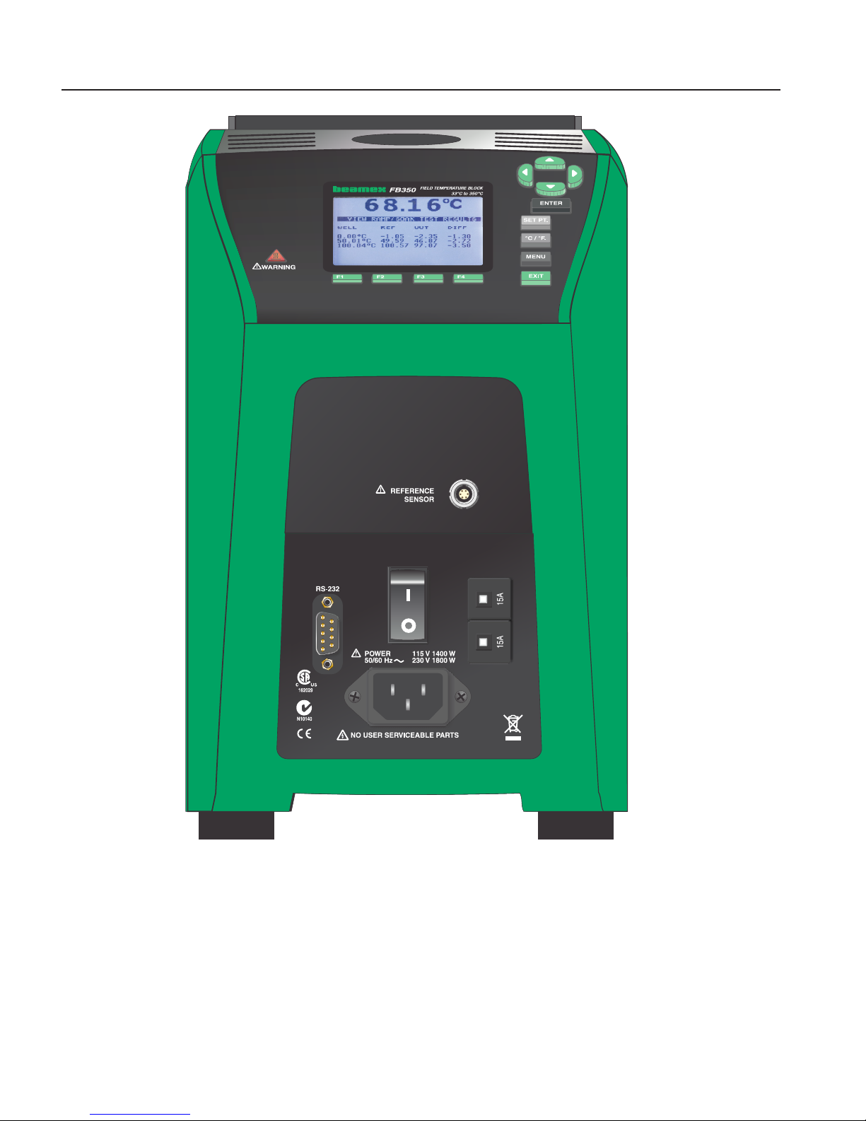
Figure 2 FBXXX Field Temperature Block
3.2 Parts and Controls
This section describes the exterior features of the Field Temperature Block. All inter-
face and power connections are found on the front of the instrument (see Figure 2).
This manual suits for next models
2
Table of contents
Other BEAMEX Test Equipment manuals


