MEGABRAS MD 5060x User manual
Formato: 135mm x 190mm
GU-1329
EXP100240
5 kV digital insulation tester
• User guide
• Technical specifications

3
MD-5060x
5 kV digital insulation tester
User guide
GU-1329
© 2009 MEGABRAS. All rights reserved.
Printed in Brazil.

4
Safety warnings
•Before to use this instrument the User guide and Safety warnings must be read
and understood.
•Safety procedures and rules for working near high voltage energized systems
must be observed during the use of this equipment. The generated voltages may
be dangerous.
•Do not connect or disconnect the test leads during the measurement.
•Do not touch the test leads before the high voltage indicator turn-off.
•Be careful not to make short-circuit between the high voltage terminals and the
“R” or “Guard” terminals while a measurement is running, because it could be
dangerous for the operator.
•Be sure that there are not any voltage difference between the points to which the
equipment will be connected to, neither between them and ground.
•The panel, terminals and connectors of the equipment must stay dry and clean.
This equipment should be used only by a trained and competent
person, strictly applying suitable safety rules.
Used symbols
Caution, risk of electric shock.
Caution, refer to User guide.
Equipment complies with current EU Directives.
Battery
Printer
Voltmeter

5
Index
1. Description............................................................................................................6
2. Control panel functions.........................................................................................7
2.1. Connections and panel items ........................................................................7
2.2. Keyboard .......................................................................................................8
2.3. Indicators .....................................................................................................10
2.3.1. Display..................................................................................................10
2.3.2. Built-in chronometer .............................................................................10
2.3.3. Real time clock .....................................................................................10
2.3.4. Test number .........................................................................................10
2.3.5. Model and serial number ......................................................................10
2.3.6. High voltage indicator ...........................................................................11
3. Power supply ......................................................................................................11
3.1. Battery status check ....................................................................................11
3.2. Battery charger............................................................................................12
4. Connecting the equipment..................................................................................13
4.1. Using the Guard terminal.............................................................................14
5. Tests definition ...................................................................................................14
5.1. Test voltage definition..................................................................................15
5.2. Selection of the operation mode..................................................................16
5.2.1. “TIMER” Mode ......................................................................................16
5.2.2. SVT Mode (step voltage tests) .............................................................17
5.2.3. “Pass / Fail” Test mode ........................................................................18
5.2.4. Normal mode ........................................................................................19
6. How to perform tests ..........................................................................................19
6.1. Polarization index (PI) .................................................................................20
6.2. Dielectric Absorption Index (DAI) ................................................................21
7. Other functions ...................................................................................................22
7.1. Filter.............................................................................................................22
7.2. Voltmeter .....................................................................................................22
7.3. Hold .............................................................................................................22
7.4. Internal memory...........................................................................................23
7.5. Auto power-off .............................................................................................23
8. Software..............................................................................................................24
8.1. USB Drivers.................................................................................................24
8.2. MegaLogg2 Software ..................................................................................27
8.3. HyperTerminal®- Real time data transfer....................................................28
8.3.1. COM number ........................................................................................28
8.3.2. HyperTerminal ......................................................................................30
9. Printer .................................................................................................................33
10. Technical specifications....................................................................................34
11. Application note 32 ...........................................................................................36
12. Warranty ...........................................................................................................39

6
1. Description
The Megabras MD-5060x is a smart, microprocessor-controlled, 5 kV
insulation tester and analyzer. Besides the conventional measurement of
insulation resistances up to 5 TΩ, its advanced features allow to
automatically measure both the Polarization Index and Dielectric
Absorption Index, thus significantly simplifying testing of transformers.
This insulation tester is portable, battery-powered equipment. Test
voltage may be chosen from 500 V to 5 kV in 100 V increments. Due to its
measurement principle (actual voltage and current readings) the accuracy
of resistance measurement is not affected by any test voltage error.
The built-in chronometer automatically counts the elapsed time since the
start of measurement. Measured values are transmitted through the data
output (USB) and are printed in the built-in printer as a registration of the
performed test. Furthermore, the measured values are stored in a non-
volatile internal memory. Up to 4000 measurements may be stored, to be
transferred afterward to a computer running the MegaLogg2 program.
This software allows a further analysis of the test results, including a
graphical representation and automatic report generation. The real time
clock and calendar, and the sequential test number, facilitates the
identification of each test, and the organization of a predictive
maintenance system by trend analysis.
Some other advanced features are useful to run the most sophisticated
insulation analysis. Step Voltage Test, configurable Pass-Fail and timed
measurements are automatically performed, with a very simple and user-
friendly setup. The measurement parameters are stored in the non-
volatile memory for an easy configuration.
The cabinet is strong and lightweight, easy to carry, impact-resistant and
suitable to be used under severe weather conditions. Thus the insulation
tester supplies very reliable and accurate measurements both in
laboratory and out in the field.

7
2. Control panel functions
2.1. Connections and panel items
Voltage output terminal (-V)
Zero reference terminal (+R)
Guard terminal (G)
Display
Keyboard
USB communication port
Power supply input
Paper feed control

8
2.2. Keyboard
Button Function Led
On/Off switch. -
It activates the filter that minimizes external
noise interference.
Indicates filter function
is on.
It shows the battery charge status on the
display.
Indicates that the
battery charger is in
operation.
When activated, it allows to program test
voltage in steps of 500 V. It enables the fast
voltage selection keys .
500 V steps test
voltage.
When activated, it allows to program test
voltage in steps of 100 V. It enables the fast
voltage selection keys .
100 V steps test
voltage.
Fast selection of 500 V test voltage. 500 V test voltage.
Fast selection of 1 kV test voltage. 1 kV test voltage.
Fast selection of 2.5 kV test voltage. 2.5 kV test voltage.
Fast selection of 5 kV test voltage. 5 kV test voltage.

9
When activated, it allows to program the
Operation Mode (Normal, SVT or TIMER).
Indicates Operation
Mode is enabled.
When activated, it allows to program the limit of
the “Pass-Fail test”.
Indicates LIM function
is on.
Turns On/Off the printing of the measured
values on the printer.
The printer is on.
Increase the value that is being programmed. -
Decrease the value that is being programmed. -
Starts the test. Indicates that the test
is being carried out.
Displays the actual voltage applied. -
Hold - freeze the last reading on the display. Hold function is on.
It displays the calculated value as the result of a
Step Voltage Test (SVT) or Polarization Index
(PI).
-
It displays the calculated value as the result of a
Dielectric Absorption Index. -
End of test. -
10
2.3. Indicators
2.3.1. Display
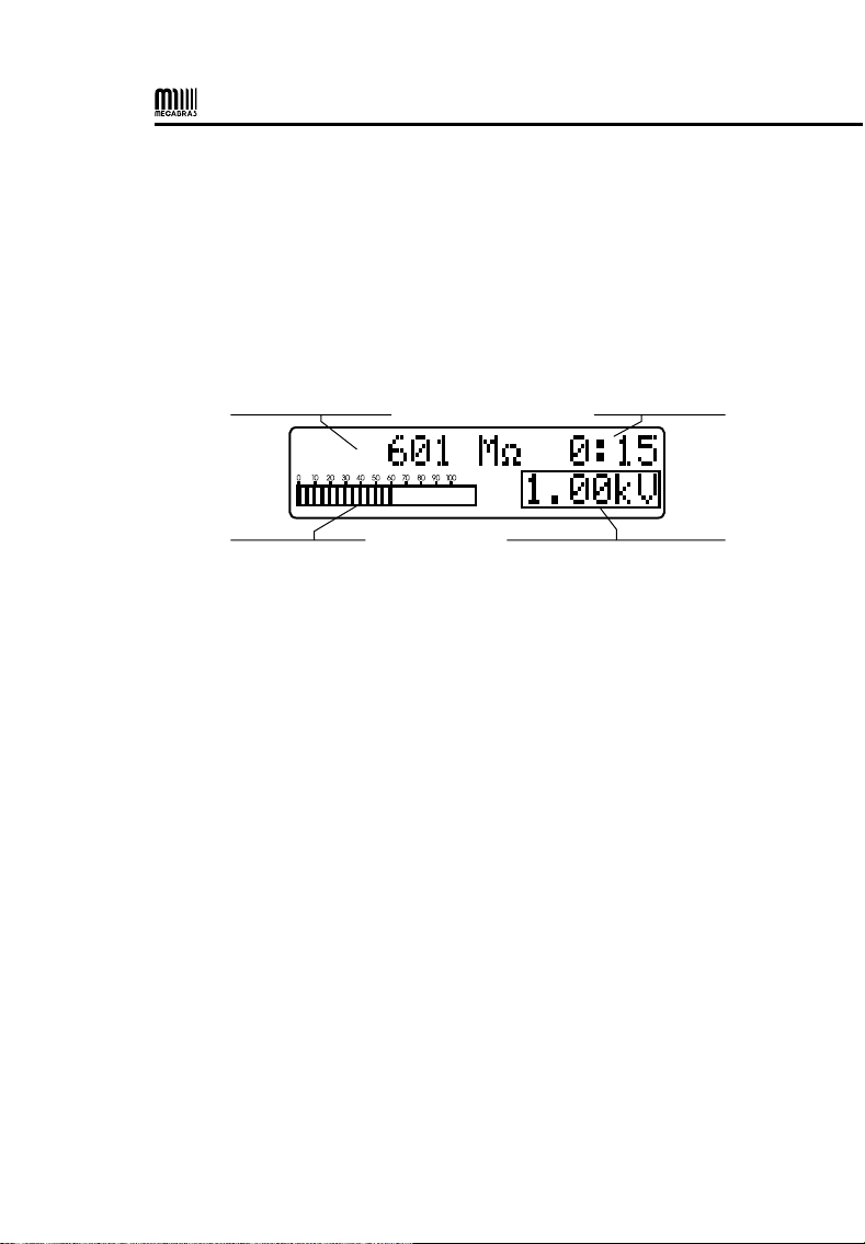
Alphanumeric LCD where the measurement result, the corresponding
measuring unit, the elapsed time since the measurement started, the
analogue indication by means of a bargraph and messages to the
operator are displayed (in English).
messages to the operator
test number
measurement results
measuring unit
analogue indication
(bargraph)
selected voltage
messages to the operator
time indication
2.3.2. Built-in chronometer
It features the elapsed time (in minutes and seconds) since test voltage is
applied.
2.3.3. Real time clock
It has a real time clock with date, hours and minutes indication, to make
identification of tests recorded in paper or in memory easier.
2.3.4. Test number
Tests are automatically numbered by the equipment to make their
identification easier. The test number is printed at the beginning of each
test and it is stored in memory.
2.3.5. Model and serial number
At the beginning of each test, the equipment model, as well its serial
number, are registered, making it possible to relate the obtained results
with their respective equipment Calibration Certificate.
11
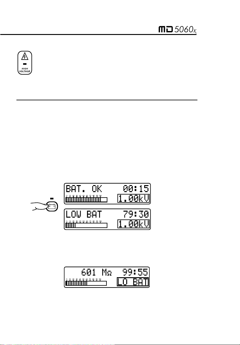
2.3.6. High voltage indicator
A
light indicator warns the occurrence of high voltage on the
output terminal during the measurement and keeps lit until the
discharging process has been completed.
3. Power supply
This equipment is powered by an internal rechargeable battery (12 V -
2.3 Ah).
3.1. Battery status check
During the measurement, it is possible to check the battery status. The
key must be pressed. If the battery charge is enough, it will read
“BAT OK”. If the charge is not enough, the message will be “LOW BAT”,
and the battery should be recharged. The analogue bargraph will give an
approximate idea of the remaining charge percentage (at least 20% is
required for a normal operation).
When the battery charge reaches the normal operation minimum value,
the message LO BAT appears automatically in the area where the test
tension value is indicates, alternating it every 1 second.
12
3.2. Battery charger
This equipment has an intelligent built-in circuit that controls the battery
charge and doesn’t allow the equipment to operate during the
charging process. In order to charge the battery, follow this procedure:
•Verify that the On/Off switch is switched off.
•Connect the equipment into the mains supply. The charging indicator
(led over key ) will turn-on red and will remain that way until the
battery is totally charged. Then the light will remain green and keep in
that way until the equipment is disconnected of the mains supply.
The following chart summarizes the meaning of LED luminous indications:
Green and red
flashing alternatively
Test of the initial condition of the battery when plugging
the mains, during one second.
Permanent red Battery under charge.
Flashing red Charging current is less than normal.
Permanent green The charging process has been successfully finished.
Battery OK.
Flashing green The charging process has finished, nevertheless the
battery hasn’t received the complete charge.
A
t the end of battery useful life, the battery must be recycled or
disposed of properly, in order to protect the environment.
The rechargeable battery does not have “memory effect” and there are no
restrictions to start charging it as many times as is needed. However the batter
y
could be damaged if remains in deep discharge for a while.
To avoid this effect, charge the battery before left the equipment in storage and
don’t let pass more than 30 days without recharge, even if the instrument wasn’t
used (under storage, the battery loses part of its charge).

13
4. Connecting the equipment
ATTENTION: For a safety operation the procedures detailed below
should be carried out with the device Powered-Off.
Check if there is no differences of potential voltage between the points
where the equipment shall will be connected to, nor between them and
the ground.
Connect the red security terminal (red cable) to the insulation tester (-V)
output terminal. Connect BNC terminal to the zero reference (+R) terminal
and the “alligators” terminals to the element to be measured as indicated
in the figure below.
The test leads in the picture are illustrative.

14
4.1. Using the Guard terminal
The G (Guard) terminal can be used or not, according to the
measurement that is going to be carried out. During measurements, the
equipment must be electrically referred to earth in order prevent the
equipment from being on a high potential, which may produce unstable
readings. When insulation is measured regarding grounding, the R
terminal is connected to earth and the condition by means of which the
equipment potential setting is fulfilled. If the measurement is performed
between two parts, which are not grounded (for example, between two
phase conductors in a tree-phase cable), the insulation tester Guard
terminal must be grounded. This implies that whenever a measurement
is performed, one of the GUARD or R terminals must be grounded,
but not both of them simultaneously.
MEGABRAS Application Note 32 explains the usage of Guard terminal for
minimizing the parasite resistance effect, whose influence one intends to
minimize.
5. Tests definition
The MD-5060x is an extremely versatile instrument that enables
automatic performance of several types of insulation tests, and records
them in its internal memory and/or prints the results. Thus, it is necessary
to appropriately define the tests to be performed, setting the following
parameters before starting the measurement:
• Test voltage
• Test duration for “TIMER” mode test
• Maximum Voltage for step voltage test (SVT)
• Minimum resistance limit for “Pass/ Fail” tests
15
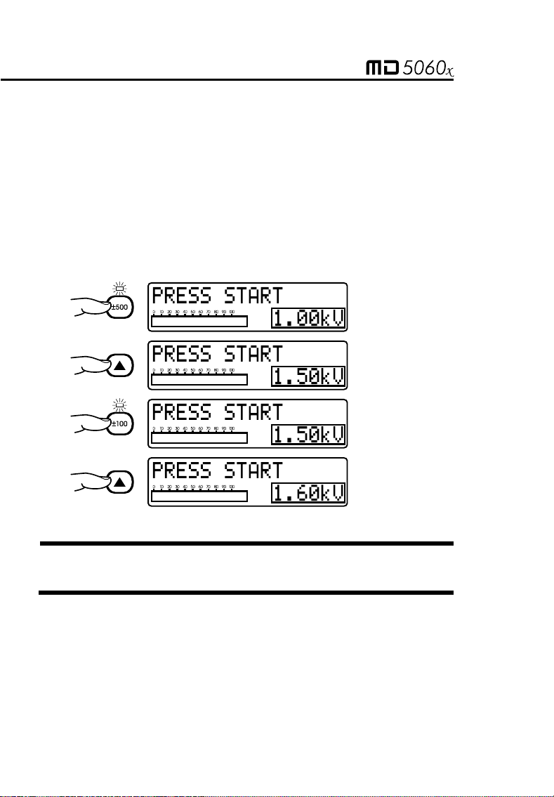
5.1. Test voltage definition
In order to define the test voltage value, first it is necessary to select one
of voltage adjustment keys: or . These keys enable both the pre-
programmed voltage selection (, , and ) and the and
keys which increase or decrease the value of the step voltage test
for 100 V or 500 V, depending on the selected voltage adjustment key. As
long as the equipment is on, the voltage adjustment key will be
selected. Press again the adjustment key selected at the moment to
leaving the test voltage selection mode.
Note: Test voltage is the only parameter that can be modified during
tests.
16
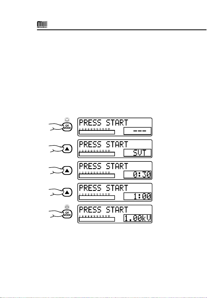
5.2. Selection of the operation mode
The MD-5060x insulation tester has four operation modes: Normal, with
“TIMER”, SVT and “Pass / Fail test”. The first three modes are selected
using the key; the “Pass/ Fail test” mode is activated pressing
key.
5.2.1. “TIMER” Mode
The use of key allows the MD-5060x setting for the performance of a
pre-set - duration test; when this mode is selected, the display shows the
programmed time. Use and keys to define the duration of the
tests in 30 seconds, 1 minute, 3 minutes, 10 minutes or 30 minutes.

17
5.2.2. SVT Mode (step voltage tests)
The use of key allows the MD-5060x setting for the performance of a
step voltage test; when this mode is selected, the display shows the SVT
abbreviation.
Under this operation mode, the user does not define a specific voltage
test, but a maximum voltage value. The device will start tests applying a
500 V voltage and increase this value in 500 V steps each minute until
reaching the programmed voltage. At each stage, the MD-5060x
measures the resistance before advancing towards the following step.
The use of voltage adjusting keys, determines the value of the highest
voltage – which will be, in all cases, a multiple of 500 V, up to a 5000 V
limit. It is advisable to use the key in order to select this value;
key may be used, but if the selected value is not a multiple of 500, it will
be rounded down.

18
The test result is calculated according to the following formula:
=
SVT
R
R
V MAX
500
After test ending, the value may be recovered by pressing key.
5.2.3. “Pass / Fail” Test mode
Press key in order to determine the lower insulation limit for type
“Pass / Fail test”. Select this value using and keys. Possible
values are 10 MΩ, 100 MΩ, 1 GΩ or 10 GΩ.
During a “Pass/ Fail test”, the MD-5060x will indicate when the insulation
resistance is lower than the programmed limit, with an intermittent beep
and the key led flashing. The key led will remain flashing until the
end of tests, or until the measurement of the resistance value is greater
than the programmed limit.

19
5.2.4. Normal mode
The normal mode is used in the resistance measurement with unique
voltage, without time limit. When selected, there are no special indications
in the display. To return to normal mode, press the key and use the
or to select the “- - -” option.
6. How to perform tests
Press key. The high voltage led turns on immediately, indicating that
the equipment internal generator is applying voltage to the element that is
being tested. The display will show the test number, the selected voltage
value and it will start the elapsed time count.
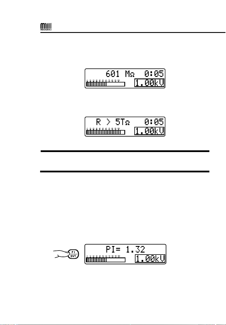
For a few seconds, the auto-range system will search for the most
convenient range for the value being measured. Meanwhile, the display
will show the message:
20
If the measured value is within the device range, the display will show the
resistance value indication and its corresponding unit, and it will start the
analogue bargraph indication.
If the measured value exceeds 5 TΩ @ 5 kV, the following message will
be read:
Note: If, during the test, it is necessary to change the test voltage, item
5.1 sequence shall be repeated
6.1. Polarization index (PI)
The key makes it possible to visualize the Polarization Index value on
the display. For this type of test, the equipment must be connected and
applying voltage to the sample for 10 minutes. After this period, the
operator must press the key to show the PI value on the instrument
display. If the key is pressed before the 10-min period has elapsed, the
display will show PI= - - -.

21
The polarization index is the ratio between the insulation resistance value
measured after 10 min and the value measured after 1 min. This index is
useful to determine whether it is necessary to perform preventive and
predictive Maintenance in order to detect any insulation resistance wear
and tear due to the excess of dust, dirt, grease, or else the action of
chemical or physical agents, etc.
=
PI R
R
10 minutes
1 minute
6.2. Dielectric Absorption Index (DAI)
The key makes it possible to visualize the Dielectric Absorption Index
value on the display. For this kind of test, the equipment should be
connected, applying voltage to the sample for 60 seconds. After this
period, the operator must press the key to read the absorption index
value on the display. If this key is pressed before the 1-minute period has
elapsed, the display will show DAI = - - -.
The Dielectric Absorption Index is the ratio between the insulation
resistance value measured after 60 seconds and the value measured
after 30 seconds. This value is useful to determine whether it is necessary
to perform preventive and predictive maintenance on the coils
(transformers, engines and motors, generators, etc.).
=
DAI R
R
60 seconds
30 seconds
Table of contents
Other MEGABRAS Test Equipment manuals


