manuals.online logo
Brands
  1. Home
  2. •
  3. Brands
  4. •
  5. BBE
  6. •
  7. Signal Processor
  8. •
  9. BBE DI-10 User manual

BBE DI-10 User manual

BBE DI-10
USER MANUAL
▲
Congratulations on the purchase of your
BBE DI-10 direct box!
The BBE DI-10 is an active direct box used for converting line out and
speaker out signals to balanced and unbalanced signals. The user also
has the ability to select between two frequency responses (flat, or
speaker compensated). Using the outputs from the DI-10, the user can
direct feed to a mixer, recorder, or sound reinforcement system.
The features that make up the BBE DI-10 are:
1. Speaker thru and Speaker input jacks.
2. 1/4” phone jack for line level signal input and output.
3. XLR jack for mic level, balanced output.
4. Filter switch to operate the speaker simulating filter.
5. Tri-mode powering for three different modes of powering:
a) internal 9V battery,
b) 9VDC external power source, and
c) 48V phantom power source through the XLR connector.
6. Tri-mode power scanning feature which scans the three power
sources and uses only the highest source of power and shuts off the
other power sources.
IMPORTANT
Before you begin, please check the contents within this box to insure
that included are:
1. The BBE DI-10.
2. Four (4) Rubber Feet for table-mount application.
3. The BBE DI-10 user’s manual.
4. 9VDC External Power Source.
Use the following illustrations as a starting point for proper placement
of the BBE DI-10.
i - BBE DI-10 INSTALLATION INSTRUCTIONS
LINE OUT
LINE IN BALANCED OUTPUT
SPEAKER OUT
SPEAKER THRU
SPEAKER INBALANCED OUTPUT
DI-10
MIXING CONSOLE
PA SPEAKER
PA SPEAKER
AMP & SPEAKERS
DI-10
MIXING CONSOLE
PA SPEAKER
PA SPEAKER
AMP & SPEAKERS
FRONT PANEL CONTROLS
1. D.C. INLET: This jack is for connecting the 9 VDC power source. The 9
VDC power plug must be of the type where the positive voltage is on the outer
ring.
2. FILTER SWITCH: This switch is used to operate the speaker simulating fil-
ter. When the filter is off, system frequency response is flat. When the filter is
on, a 4th order filter network is activated and the system frequency response is
6dB down at 4kHz.
3. LINE OUT: This 1/4” phone jack provides an unbalanced line level output.
REAR PANEL CONNECTIONS
4. SPEAKER THRU AND SPEAKER INPUT: These are 1/4” mono phone
jacks. When using an amplifier, the output from the power amp section connects
to the ‘speaker input’ jack while the amplifier speakers connect to the ‘speaker
through’ jack.
CAUTION: Never operate an amplifier featuring a tube power stage without a
connection to a speaker or sufficient power resistor.
5. LINE INPUT: This is a 1/4” mono phone jack for line level signal insertion.
NOTE: Connecting a 1/4” male plug to either the speaker in jack or the line in
jack will activate the internal 9 volt battery.
6. BALANCED OUT: This XLR jack provides a mic level balanced output. Pin
2 being the ‘hot’ pin. The DI-10 can also be phantom powered through this jack.
NOTE: This unit may be powered by three (3) different modes.
1. Internal 9 volt battery.
2. 9 VDC external power source.
3. 48v phantom power source.
BBE DI-10 INSTALLATION INSTRUCTIONS - 1
1 2 3 4 5 6
5381 Production Drive, Huntington Beach, CA 92649
Ph: (714) 897-6766 • Fax: (714) 896-0736
Covered by U.S. Patent 4,482,866 and other U.S. and foreign patents pending.
BBE is the registered trademark of BBE Sound, Inc.
SPECIFICATIONS
FREQUENCY RESPONSE
FILTER OFF . . . . . . . . . . . . . . . . . . .5Hz to 30kHz
FILTER ON . . . . . . . . . . . . . . . . . . . .40Hz to 4kHz
SIGNAL TO NOISE RATIO . . . . . . . . . . . .108dB (Filter Out)
(USING A 9V BATTERY)
TOTAL HARMONIC DISTORTION . . . . .0.02% (20hz - 20khz)
INPUT CHARACTERISTICS
INPUT IMPEDANCE . . . . . . . . . . . .50k OHMS (Line In)
. . . . . . . . . . . . . . . . . . . . . . . . . . . . .470k OHMS (Speaker In)
LINE INPUT LEVEL . . . . . . . . . . . . .+10dBu (Battery)
. . . . . . . . . . . . . . . . . . . . . . . . . . . . .+24dBu (Phantom Power Supply)
SPEAKER INPUT LEVEL . . . . . . . .+40dBu (Battery)
. . . . . . . . . . . . . . . . . . . . . . . . . . . . .+54dBu (Phantom Power Supply)
OUTPUT CHARACTERISTICS
OUTPUT IMPEDANCE . . . . . . . . . .600 OHMS (XLR)
. . . . . . . . . . . . . . . . . . . . . . . . . . . . .1k OHM (Line Out)
POWER REQUIREMENTS
PHANTOM . . . . . . . . . . . . . . . . . . . .+48v (Via XLR Jack)
D.C. INLET . . . . . . . . . . . . . . . . . . . .+9vdc Minimum of 100ma
BATTERY . . . . . . . . . . . . . . . . . . . . .+9vdc (500hrs)
WARRANTY
Warranty registration of the unit to BBE Sound Inc. is not necessary. However, it is strongly recommended that a
copy of the bill of sale is retained for future reference.
IT IS THE SOLE RESPONSIBILITY OFTHE END USER TO PROVIDE THE BILLOF SALE OR
OTHER MEANS OF PROOF OF PURCHASE TO VALIDATE THE WARRANTY IFWARRANTY SER-
VICE IS REQUIRED.
The BBE DI-10 Active Direct Box is warranted against defects in material and workmanship for a period of five
(5) years from date of purchase from BBE Sound, Inc. or from an authorized dealer.
During this period, we will repair units free of charge providing that they are shipped prepaid to BBE Sound, Inc.,
5381 Production Drive, Huntington Beach, CA 92649. BBE Sound, Inc. will pay return UPS shipping charges
within the USA. All charges related to non-U.S. shipping, including customs clearance, will be billed. The warran-
ty will be honored for the longer of either 90 days from the date of any service or the remainder of the original 5
Year factory warranty.
The warranty will be considered null and void by BBE Sound, Inc. if any of the following is found:
1. The equipment has been physically damaged.
2. The equipment shows signs of abuse.
3. The equipment has been electrically damaged by improper connection or attempted repair by the customer or a
third party.
4. The equipment has been modified without authorization.
5. The bill of sale indicates that the purchase date of the equipment is not within the warranty period.
All non-warranty repairs are warranted for a period of 90 days from the date of service.
BBE Sound, Inc. is NOT LIABLE FOR CONSEQUENTIAL DAMAGES. Should the unit fail to operate for any
reason, our sole obligation is to repair the unit as described above.
Other BBE Signal Processor manuals

BBE Sonic Maximizer DI-100 User manual

BBE

BBE Sonic Maximizer DI-100 User manual

BBE Sonic Maximizer 3012 User manual

BBE

BBE Sonic Maximizer 3012 User manual

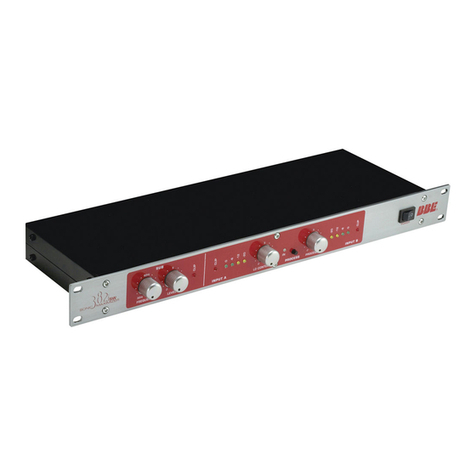
BBE Sonic Maximizer 482i User manual

BBE

BBE Sonic Maximizer 482i User manual

BBE Sonic Maximizer 1002 User manual

BBE

BBE Sonic Maximizer 1002 User manual

BBE Sonic Maximizer DI-1000 User manual

BBE

BBE Sonic Maximizer DI-1000 User manual

BBE Sonic Maximizer 322 User manual

BBE

BBE Sonic Maximizer 322 User manual

BBE Sonic Maximizer 882i User manual

BBE

BBE Sonic Maximizer 882i User manual

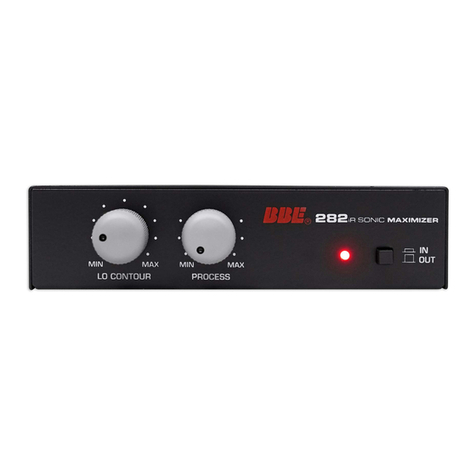
BBE Sonic Maximizer 282i User manual

BBE

BBE Sonic Maximizer 282i User manual

BBE SONIC MAXIMIZER 482 User manual

BBE

BBE SONIC MAXIMIZER 482 User manual

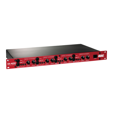
BBE DI-400 User manual

BBE

BBE DI-400 User manual

BBE Sonic Maximizer 262 User manual

BBE

BBE Sonic Maximizer 262 User manual

BBE Sonic Maximizer DI-100x User manual

BBE

BBE Sonic Maximizer DI-100x User manual

BBE Sonic Maximizer 362XL User manual

BBE

BBE Sonic Maximizer 362XL User manual

BBE Sonic Maximizer 882i User manual

BBE

BBE Sonic Maximizer 882i User manual

BBE 462 User manual

BBE

BBE 462 User manual

BBE Sonic Maximizer BBE 882 User manual

BBE

BBE Sonic Maximizer BBE 882 User manual

BBE Audio Restoration System BBE ARS User manual

BBE

BBE Audio Restoration System BBE ARS User manual

BBE Sonic Maximizer 382i User manual

BBE

BBE Sonic Maximizer 382i User manual

BBE 382ISW SONIC MAXIMIZER User manual

BBE

BBE 382ISW SONIC MAXIMIZER User manual

BBE Sonic Maximizer 411 User manual

BBE

BBE Sonic Maximizer 411 User manual

BBE 422A User manual

BBE

BBE 422A User manual

Popular Signal Processor manuals by other brands

EVS Xeebra Installation and configuration manual

EVS

EVS Xeebra Installation and configuration manual

Wilson Electronics 2B1401 installation guide

Wilson Electronics

Wilson Electronics 2B1401 installation guide

Intel 2920 Design handbook

Intel

Intel 2920 Design handbook

turck MS96 quick start guide

turck

turck MS96 quick start guide

Extron electronics MGP Pro Series user guide

Extron electronics

Extron electronics MGP Pro Series user guide

Texas Instruments TMS320VC5402 datasheet

Texas Instruments

Texas Instruments TMS320VC5402 datasheet

Yamaha MTX Series Setup manual

Yamaha

Yamaha MTX Series Setup manual

Atlas IED ASP-MG24 owner's manual

Atlas IED

Atlas IED ASP-MG24 owner's manual

Meyer Sound Control Electronics Unit S-1 operating instructions

Meyer Sound

Meyer Sound Control Electronics Unit S-1 operating instructions

Boss Audio Systems RRV-10 instructions

Boss Audio Systems

Boss Audio Systems RRV-10 instructions

Steg DSP 6TO8 owner's manual

Steg

Steg DSP 6TO8 owner's manual

IFoundry Systems IrDA SIR Endec Chip (SOP8) IFSYS -7000 Product brief

IFoundry Systems

IFoundry Systems IrDA SIR Endec Chip (SOP8) IFSYS -7000 Product brief

Befaco Muxlicer user manual

Befaco

Befaco Muxlicer user manual

Anritsu MX371054A Operation manual

Anritsu

Anritsu MX371054A Operation manual

TC Electronic DB8 MKII Hardware installation guide

TC Electronic

TC Electronic DB8 MKII Hardware installation guide

HP HP 8673C Operating and service manual

HP

HP HP 8673C Operating and service manual

miniDSP 10X10 HD user manual

miniDSP

miniDSP 10X10 HD user manual

Klark Teknik DN716 Operating and service information

Klark Teknik

Klark Teknik DN716 Operating and service information

manuals.online logo
manuals.online logoBrands
  • About & Mission
  • Contact us
  • Privacy Policy
  • Terms and Conditions

Copyright 2025 Manuals.Online. All Rights Reserved.