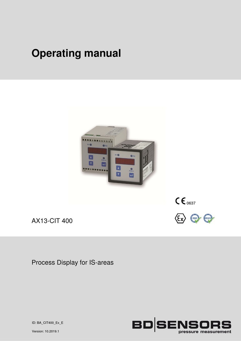
BD Sensors CIT 400 User manual

BD SENSORS GmbH
BD-Sensors-Straße 1 Telefon +49 (0) 9 35 / 98 11- 0 www.bdsensors.de
D - 95199 Thierstein Telefax +49 (0) 9 35 / 98 11- 11 info@bdsensors.de
Operating manual
CIT 400
Process Display
ID: BA_CIT400_E
Version: 10.2019.1

2
CIT 400
pressure and level
Table of contents
1. General and safety-related information on this operating manual............................................3
1.1 Symbols used..................................................................................................................... 3
1.2 Staff qualification ................................................................................................................3
1.3 Intended use.......................................................................................................................4
1.4 Limitation of liability and warranty.......................................................................................4
1.5 Safe Handling.....................................................................................................................4
1.6 Scope of Delivery ...............................................................................................................4
2. Product identification................................................................................................................5
3. Mounting ..................................................................................................................................5
3.1 Mounting and safety instructions ........................................................................................ 5
3.2 Top-hat rail mounting..........................................................................................................6
3.3 Front panel mounting..........................................................................................................6
3.4 Electrical installation ........................................................................................................... 6
3.5 Installation example............................................................................................................ 8
4. Overvoltage protection.............................................................................................................9
5. Operation ...............................................................................................................................10
5.1 Operating and display elements ....................................................................................... 10
5.2 Menu operation ................................................................................................................ 10
5.3 Description of the menu levels .........................................................................................11
5.4 Structure of the menu system........................................................................................... 11
5.5 Menu list ........................................................................................................................... 13
6. Troubleshooting .....................................................................................................................18
7. Programming examples .........................................................................................................19
7.1 Level measurement .......................................................................................................... 19
7.2 Interface level measurement ............................................................................................20
7.3 In bounds / out of bounds ................................................................................................. 21
7.4 Changing of pumps .......................................................................................................... 22
8. Maintenance ..........................................................................................................................22
9. Removal from Service............................................................................................................22
10. Service / repair.....................................................................................................................23
10.1 Recalibration .................................................................................................................. 23
10.2 Return............................................................................................................................. 23
11. Disposal ...............................................................................................................................23
12. Warranty Terms ...................................................................................................................23

3 www.bdsensors.
de
CIT 400
1. General and safety-related information on this operating manual
This operating manual enables safe and proper handling of the product, and forms part of the
device. It should be kept in close proximity to the place of use, accessible for staff members at
any time.
All persons entrusted with the mounting, installation, putting into service, operation, mainte-
nance, removal from service, and disposal of the device must have read and understood the
operating manual and in particular the safety-related information.
Complementary to this operating manual the current data sheet has to be adhered to.
Download this by accessing www.bdsensors.de or request it by e-mail or phone:
In addition, the applicable accident prevention regulations, safety requirements, and country-
specific installation standards as well as the accepted engineering standards must be observed.
1.1 Symbols used
Warning word
- Type and source of danger
- Measures to avoid the danger
Warning word Meaning
DANGER
- Imminent danger!
- Non-compliance will result in death or serious injury.
WARNING
- Possible danger!
- Non-compliance may result in death or serious injury.
CAUTION
- Hazardous situation!
- Non-compliance may result in minor or moderate injury.
NOTE - draws attention to a possibly hazardous situation that may result in property damage in
case of non-compliance.
Precondition of an action
1.2 Staff qualification
Qualified persons are persons that are familiar with the mounting, installation, putting into ser-
vice, operation, maintenance, removal from service, and disposal of the product and have the
appropriate qualification for their activity.
This includes persons that meet at least one of the following three requirements:
- They know the safety concepts of metrology and automation technology and are familiar
therewith as project staff.
- They are operating staff of the measuring and automation systems and have been instruct-
ed in the handling of the systems. They are familiar with the operation of the devices and
technologies described in this documentation.
- They are commissioning specialists or are employed in the service department and have
completed training that qualifies them for the repair of the system. In addition, they are au-
thorized to put into operation, to ground, and to mark circuits and devices according to the
safety engineering standards.
All work with this product must be carried out by qualified persons!

4
CIT 400
pressure and level
1.3 Intended use
The multifunctional process transmitter CIT 400 has been especially developed for the supply
and data acquisition of 2- and 3-wire-sensors with current signal. The micro-controlled device
collect the signal of the sensor and show the measured value in a 4-digit LED-display. For sim-
ple handling, the device features an extensive menu system with several menu levels. The dis-
play can be freely programmed via three push-buttons in the touchpad, which allow navigation
through the menu system and feeding in values. The combination of independent limit value re-
lays and freely scaleable analogue output allows the solution of nearly every measurement task.
The device is equipped with a password access protection to permit operation of the complete
menu system only to authorized persons.
The user must check whether the device is suited for the selected use. In case of doubt, please
BD|SENSORS assumes no liability for any wrong selection and the consequences thereof!
The technical data listed in the current data sheet are engaging and must absolutely be com-
plied with. If the data sheet is not available, please order or download it from our homepage:
http://www.bdsensors.de
WARNING
Danger through incorrect use
- In order to avoid accidents, use the device only in accordance with its
intended use.
1.4 Limitation of liability and warranty
Failure to observe the instructions or technical regulations, improper use and use not as intend-
ed, and alteration of or damage to the device will result in the forfeiture of warranty
and liability claims.
1.5 Safe Handling
NOTE - Treat the device with care both in the packed and unpacked condition!
NOTE - The device must not be altered or modified in any way.
NOTE - Do not throw or drop the device!
NOTE - The device is state-of-the-art and is operationally reliable. Residual hazards may origi-
nate from the device if it is used or operated improperly.
1.6 Scope of Delivery
Check that all parts listed in the scope of delivery are included free of damage, and have been
delivered according to your purchase order:
•CIT 400
•this operating manual
•for front panel housing: additionally, 2 screw-in clamps

5 www.bdsensors.
de
CIT 400
2. Product identification
The device can be identified by its type plate. It provides the most important data. By the order-
ing code, the product can be clearly identified. For identification of the firmware, the program
version (e. g. P074) will appear for about 1 second in the display after starting up the device.
Please hold it ready for inquiry calls.
Fig. 1: Example of manufacturing label
NOTE - The manufacturing label must not be removed!
3. Mounting
3.1 Mounting and safety instructions
DANGER
Danger of death from electric shock
- Always mount the device in a de-energized condition!
DANGER
Danger of death from improper installation
- Installation must be performed only by appropriately qualified persons
who have read and understood the user manual.
NOTE -For operation and maintenance work, the operator is obligated to observe the infor-
mation on the warning signs possibly affixed to the device.
The transmitter mounting place has to be selected according to certain criteria.
Please avoid strictly:
• direct sunlight (use weatherproof cover if necessary)
• heat emitting objects (max. ambient temperature: +40°C
• objects with strong electromagnetic fields (e. g. frequency converters)
• corrosive chemicals or gas
• mechanical shocks
• vibrations
• radioactive radiation
• installation close to footpaths or travel ways
Please observe the following points when selecting the measurement place:
• The installation surface must be free of vibrations.
• The ambient temperature must be between -20º C and +60 ºC
• Keep away from power lines or frequency converters (approx. 100 m).
Type designation Ordering code Serial number

6
CIT 400
pressure and level
3.2 Top-hat rail mounting
The unit will be fastened by snapping it onto an installed DIN top-hat rail with a minimum length
of 70 mm.
3.3 Front panel mounting
The front panel housing has to be fastened by using 2 screw-in clamps.
•Push the panel housing front sided into the panel cut-out as far as possible.
•Hang the 2 screw-in clamps into 2 opposed undercuts in the housing.
•After that tighten the two set screws while holding the screw-in clamps firmly with the other
hand.
3.4 Electrical installation
For installation the lawful regulations of the respective country have to be observed.
The power supply must be separately protected by a 6 A slow-blow fuse and has to be iso-
lated from other facility parts (separate turn-off, e. g. by using an automatic cut-out with
>B< characteristics).
Please note during installation that electronic components may be destroyed by electrostatic
bursts. Therefore, avoid high electrostatic charge by providing proper ground connection.
Before impressing the rated voltage, the transmitter and sensor installation must be correctly
completed and checked.
All outer circuits, wires and lines connected to the device must have a minimum isolation re-
sistance of 250 V. If the voltage exceeds 42 VDC, a minimum isolation resistance
of 500 kΩ is necessary.
The section dimension of the power supply wires must be 0.75 mm² in accordance to
IEC 227 or IEC 245. To observe the degree of ingress protection, please refer to the technical
data in the appendix. The maximum switching voltage on the relay contacts must not exceed
250 V. Check if the devices’ power supplies have to be integrated into the emergency shutdown
conception of the facility.
When installing the device, the different types of housing (top-hat rail and front panel) have no
effect on the denomination of the terminal clamps, only their locations will vary.
For the electrical connection, please note the device’s configuration.
One copper wire with a maximum cross section of 2.5 mm² can be connected per clamp. Con-
nection is made by using terminal clamps and a screwdriver with a 2.5 mm blade. The terminal
clamps are normally unscrewed on delivery. Nevertheless, this must be checked before con-
necting the power supply or the signal wires.
Before first connection, it is necessary to have a slight pressure on the screw of the clamp-
ing connection to ensure a safe opening and a correct connection.

7 www.bdsensors.
de
CIT 400
Standard:
top-hat rail housing front panel housing
Optionally:
top-hat rail housing front panel housing
Fig. 2 Terminal clamps

8
CIT 400
pressure and level
3.5 Installation example
The power supply of the transmitter has principally not been drawn but is mandatory. The ex-
amples listed below represent only a selection of possible combinations of the sensor
CIT 400.
Example 1: CIT 400 with analogue output, supplied by a 2-wire-sensor; with alarm relay
Fig. 3 CIT 400 with 2-wire-sensor
Example 2: CIT 400 with analogue output supplied by a 3-wire-sensor; with alarm relay
Fig. 4 CIT 400 with 3-wire-ultrasonic-sensor
Example 3: CIT 400 as transmitter, when supplied with voltage signals from a pickup or to
simulate an external sensor with voltage output at the CIT 400.
Fig. 5 CIT 400 with pickup feeding a mA-signal
Limit value
message
Rel. 1
Writer
Display
Limit value
message
Rel. 1
Writer
Display
Limit value
message
Writer
Display
Sensor
4-20 mA

9 www.bdsensors.
de
CIT 400
4. Overvoltage protection
For effective protection of the process transmitters, it is necessary to protect power supply and
mA outputs by using overvoltage protection devices. We recommend:
- Data Pro 2x1 24 V/24 V for potential-free (galvanically isolated) data lines, 25 A leakage
current as well as automatic self-control by failsafe diodes, which interrupt the current
signal in case of error and cause an error message, given out by the process transmitter.
- Ener Pro 220 Tr for 230 V power supply of the process transmitter. Leakage current 20.000 A
and high capacity (up to 16 A) for safe and durable protection of several devices simultane-
ously.
Fig. 6 Overvoltage protection of analogue inputs
Fig. 7 Overvoltage protection of analogue outputs
Fig. 8 Overvoltage protection of power supply
Please pay attention to the non-reversed connection of the Data Pro (p-side to transmitter) as
well as to a correct, straight wiring supply. The grounding (earth) must lead to the unprotected
side. The cross section of the ground wire should be 6 mm² at least!
Sensor supply
Analogue
output
Writer
Display
Supply

10
CIT 400
pressure and level
5. Operation
5.1 Operating and display elements
standard option
Fig. 9 Touchpad
The touchpad of the process transmitter was designed to be user-friendly. So even an untrained
user will be able to carry out easily all fundamental tasks which ensure a correct operation of
the unit. The indication of the measured value as well as the configuration of the individual pa-
rameters occur through a menu via the display. The individual functions can be set with the help
of three miniature push buttons located in the front.
5.2 Menu operation
The menu system is a closed system allowing you to scroll both forward and backward through
the individual set-up menus to navigate to the desired setting item. To leave a menu item, push
the Enter-button. To leave the menu system completely, the last menu item has to be scrolled
over or you will have to wait until the device changes automatically to display mode (about
1 minute after pushing a button). All settings are permanently stored in an EEPROM and there-
fore available again even after disconnecting the device from the supply voltage.
•"▲" button: with this button you move forward in the menu system or increase the dis-
played value; it will also lead you to operating mode
•"▼" button: with this button you move back in the menu system or decrease the displayed
value; it will also lead you to operating mode
•Enter-button: with this button the menu levels can be entered to reach the menus items;
use this button also to confirm the menu items and the set values
LED relay
1
LED relay
4
LED relay
2
LED relay 3
LED Alarm
"▼" - button
"▲" - button
display
LED relay 1 LED relay 2
Enter-
button

11 www.bdsensors.
de
CIT 400
5.3 Description of the menu levels
There are 8 menu levels, which can be chosen separately.
Paof = password protection
diSP = display
SinP = signal input (analogue input)
Lin = linearization
rELn = contacts (relays)
Aout = analogue output
tESt = simulation- / testing mode
ALLG = unit parameters
CAL = calibration
5.4 Structure of the menu system
The menu system and the menu items have been designed as simply as possible. Each indi-
vidual menu item is described below in detail allowing a straightforward and quick configuration
of your device. The grey marked menus are not available in the standard version.
Please follow the manual meticulously and remember that changes of the adjustable pa-
rameters become only effective after pushing the "OK" button and after leaving the menu
item. If an error message appears in the display after pushing the enter-button, the set
value will not be stored.

12
CIT 400
pressure and level
Fig. 10 Menu system P074
Display mode
(measured value is
displayed)
Parameters for
calibration
Menu CAL
Parameters of the
display
Menu diSP
Parameters of
signal input
Menu SinP
Parameters of
contacts
Menu rELn
Parameters of
analogue output
Menu Aout
Simulation/
testing mode
Menu tESt
Unit
parameters
Menu ALLG
Password
activation
Menu PAoF
Scaled measure-
ment values
Menu diS1
Starting point of
measuring range
Menu ZPin
Switching mode
hysteresis/compare
Menu HY1/CP1
Output
signal
Menu outY
Status
relay 1
Menu R1Si
Relais
exchange
Menu CHAn
Adjusting signal
input of offset
Menu SioF
1
up to
4
Input signal
in mA
Menu diS2
End point of
measuring range
Menu EPin
Switching point
relay 1
Menu S1on
Input signal
in %
Menu diS3
Reset point
relay 1
Menu S1of
Output signal
in %
Menu diS4
Contact inverting
relay 1
Menu In1
Scaled value
with offset and
display offset
Menu diS5
Switch-on delay
relay 1
Menu D1on
Output signal
in mA
Menu diS6
Switch-off delay
relay 1
Menu D1of
Switching mode
hysteresis/compare
Menu HY2/CP2
Switching point
relay 2
Menu S2on
Reset point
relay 2
Menu S2of
Contact inverting
relay 2
Menu In2
Switch-on delay
relay 2
Menu D2on
Switch-off delay
relay 2
Menu D2of
min. measured
value
Menu ZPou
Status
relay 2
Menu R2Si
Password
setting
Menu PAnr
Adjusting signal
input of span
Menu SiSP
max. measured
value
Menu EPou
Status
alarm relay
Menu ALSi
Default
setting
Menu LoAD
Status
analogue output
Menu AnSi
On
OFF
On
OFF
On
OFF
0 mA
4 mA
20 mA
freely selectable (Si)
Decimal point
position
Menu dP
Switching mode
hysteresis/compare
Menu HY3/CP3
Switching point
relay 3
Menu S3on
Reset point
relay 3
Menu S3of
Contact inverting
relay 3
Menu In3
Switch-on delay
relay 3
Menu D3on
Switch-off delay
relay 3
Menu D3of
Switching mode
hysteresis/compare
Menu HY4/CP4
Switching point
relay 4
Menu S4on
Reset point
relay 4
Menu S4of
Contact inverting
relay 4
Menu In4
Switch-on delay
relay 4
Menu D4on
Switch-off delay
relay 4
Menu D4of
OFF
2
3
4
Parameters for
linearization
Menu Lin
Linearization
on / off
Menu Lin on/ off
Number of
supporting point
Menu n
Status
relay 3
Menu R3Si
On
OFF
Status
relay 4
Menu R4Si
On
OFF
Supporting point
input signal
Menu in n
Supporting point
output signal
Menu ou n
Number of supporting point: n = 2 ... 32
"n" stands for the number of the supporting point

13 www.bdsensors.
de
CIT 400
5.5 Menu list
Menu level diSP - parameter of the display (mode)
The menus "dIS1" to "dIS6" determine the display mode.
Display - scaled measurement value
dIS1
Indicates the scaled measurement value on the display. The indicated
value may vary between 0.000 and 9999. Confirm with Enter after select-
ing "dIS1" in order to activate this
mode.
Display - input in mA
dIS2 Indicates the input signal in mA on the display. In this mode, the unit vir-
tually operates as a mA-meter which indicates the sensor current. Con-
firm with Enter after selecting "dIS2" in order to activate this display
mode.
Display - input in %
dIS3 Indicates the input signal as percentage on the display. The value
ranges
between 0 and 100 % and has a direct relation to the sensor signal
which varies within a range of 4 to 20 mA. Confirm with
Enter after selecting "dlS
3" in order to activate this display mode.
Display - analogue output in %
dIS4 Indicates the output signal as percentage on the display. The value rang-
es between 0 and 100 % and has a direct relation to the analogue out-
put of the transmitter which varies within a range of 4 to 20 mA (depend-
ing on the value selected in menu "outY"). Confirm with Enter after se-
lecting "dlS4" in order to activate this display mode.
Display - scaled measurement value with offset and display offset
dIS5 Indicates the scaled measurement value with the added offset on the
display. The indicated value may vary between 0.000 and 9999. The dis-
play offset must be entered in the menu "dIS5". Confirm with Enter after
selecting "dlS5" in order to
activate this display mode. The value set here
will be used as display offset and will be added to the investigated meas-
urement value. Use the arrow keys to enter the numeric value and con-
firm with Enter.
Display - output in mA
dIS6 Indicates the output signal in mA on the display. In this mode, the unit
virtually operates as a mA-meter which represents the analogue output
of the transmitter. This is essential for the user to check the signal circuit
to operate correctly and if subsequent evaluation units indicate the same
values. Confirm with Enter after selecting "dlS6" in order to activate this
display mode.

14
CIT 400
pressure and level
Menu level SinP - parameter of signal input (analogue input)
The subordinate menu items are used to define the measurement span of the analogue input
for 4 mA and 20 mA.
Signal input - starting point of measuring range
ZPIn The measurement value for the analogue input at 4 mA must be entered
here. Normally this value is 0, which means 0 m at 4 mA in case of a
pressure probe with a measurement range of 0 to 6 m water column
height. Use the arrow keys to enter the numeric value and confirm with
Enter.
Signal input - end point of measuring range
EPIn The measurement value for the analogue input at 20 mA must be en-
tered here. Normally this is the maximum measurement span, resulting
from the example above, i. e. a value of 6. Use the arrow keys to enter
the numeric value and confirm with Enter.
Signal input - decimal point position
dP Here you can define the decimal point position. Use the arrow keys to
move the decimal point and confirm with Enter.
Menu level Lin - parameter of the linearization
Via this menu level, you can linearize the input signal (sensor) by a supporting point. This func-
tion is essential when the sensor signal is not linear to the output signal of the process transmit-
ter. By this function, it is possible to get an output signal nearly linear to the filling volume in ir-
regular shaped tanks.
Linearization - activation / deactivation
Lion/Liof With this menu, the linearization can be switched on or off. In the switch-
off mode
,
the supporting point
s
are not taken into account.
Linearization - number of supporting points
n In this menu, the number of supporting points has to be set. The permis-
sible range
is set
from 2 to 32
supporting points
.
Linearization - input signal of supporting points
in n In this menu, the first part of the supporting points has to be defined,
whereas "n" in the menu designation is replaced by the number of the
supporting point (in 1, in 2, ... in32). The sensor signal of the respective
supporting point which lies on the input must be entered. In the following
menu, the corresponding output signal must be set. The input value is
based on
the scaling limits
defined in the menu level
SinP
.
Linearization - output signal of the supporting points
ou n In this menu, the second part of the supporting points has to be defined,
whereas "n" in the menu designation is replaced by the value of the re-
spective supporting point (ou 1, ou 2, ... ou32). The value has to be en-
tered corresponding to the value for reaching a supporting point. Be-
tween two supporting points, the course is linear. Please note that the
supporting points must be entered in ascending sequence, i. e. the value
for n+1 has to be higher than the value for n. The output signal on the
analogue output is developed by the indicated value, whereas the pa-
rameters from the menu level
Aout
are used.

15 www.bdsensors.
de
CIT 400
Menu level rELn - parameter of the contacts (relais)
The menu items of this level are responsible for the limit value settings and the switching behav-
iour of the relays. Since the menus for the relays have been conceived identically, the descrip-
tion is the same for all menus. This menu level can be called up by pressing Enter like any other
menu. After that, the respective relay must be selected. This can be achieved by selecting the
numbers of the relay with the arrow keys. Confirm your selection with Enter (standard: 2 relays /
option: 4 relays).
Contacts - switching mode hysteresis/compare
HY 1 / CP 1
HY 2 / CP 2
HY 3 / CP 3
HY 4 / CP 4
With this menu, you can define the switching logic of the relays. It is pos-
sible to select between the so-called hysteresis mode HY X (limit level)
and the compare mode CP X (in bounds/out of bounds). Select with ar-
row keys as usual – HYon indicates the selected hysteresis mode (limit
level). CPon will indicate the window mode (in bounds/out of bounds).
Confirm with Enter.
(compare 7. Programming examples)
Contacts - switching point
S1on
S2on
S3on
S4on
This menu defines the upper switching point of the respective relay. The
programming example shows the function of this menu. In hysteresis
mode (limit level), this value determines e. g. the turn-on point. In window
mode (in bounds/out of bounds), this value determines e. g. the in
bounds upper switching point. The value can be set using the arrow keys.
Confirm with Enter.
Contacts - reset point
S1of
S2of
S3of
S4of
This menu defines the lower switching point of the respective relay. The
programming example shows the function of this menu. In hysteresis
mode (limit level), this value determines e. g. the reset point. In compare
mode (in bounds/out of bounds), this value determines e. g. the in
bounds lower switching point. The value can be set using the arrow keys.
Confirm with Enter.
Contacts - inverting
In 1
In 2
In 3
In 4
This menu allows you to invert the relay position. In hysteresis mode
(limit level), the upper and lower switching points will be changed. In
window mode (in bounds/out of bounds), the switching behaviour will
change from in bounds to out of bounds. Please note that this determina-
tion is valid only in case of activated auxiliary power, as the relay has to
be powered with auxiliary power depending on the parameter setting.
Relay inversion will be set by using the arrow keys. "St" in the display
indicates the standard position, "In" the inverted relay position. Confirm
the setting with Enter.
Contacts - switch-on delay
D1on
D2on
D3on
D4on
This menu is used to define a switch-on delay within a range from 0 to
100 seconds for the selected relay. Set the delay with the arrow keys
and confirm with Enter.

16
CIT 400
pressure and level
Contacts - switch-off delay
D1of
D2of
D3of
D4of
With this menu, you can define a switch-off delay within a range from 0
to 100 seconds for the selected relay. Set the delay with the arrow keys
and confirm with Enter.
Menu level Aout - analogue output
The settings for the analogue signal output are determined in the menu items.
Analogue output - output signal
outY This menu defines the output signal range. You can choose between
the following settings: 4-20 mA, 0-20 mA, 20-4 mA and 20-0 mA. Se-
lect by using the arrow keys and confirm with Enter.
Analogue output - minimum measurement value
ZPou In this menu, you can enter the minimum measurement value which
should correspond to the analogue output signal, e. g. 0 meters. If the
sensor reaches this value, the output will be e. g. 4 mA if the signal
range in menu "outY" was set to 4
-
20 mA.
Analogue output - maximum measurement value
EPou Enter the maximum measurement value which has to correspond to
the analogue output signal here. If, for example,
"ZPIn" and "EPIn" of a
pressure sensor are given with 0 up to 6 meters, the menu "EPou" can
be set on 5 meters. If the sensor reaches this value, the output will be
e.
g. 20 mA if the signal range in
menu
"outY" was set to 4
-
20 mA.
Menu level tESt - simulation / testing mode
In this menu level, all test and simulation menus are located. The simulation options cover a
manual relay control as well as an analogue output signal simulation.
Simulation - status of the relays
R1SI
R2SI
R3SI
R4SI
ALSI
This menu is used to simulate the relay conditions. Menu "ALSI" is re-
sponsible for the alarm relay. By using the arrow keys, it is possible to
simulate the "energized" (ON) and "de-energized" (OFF) condition. The
relay will change its condition immediately after selection. Pressing En-
ter will exit the respective simulation menu.
Simulation - status of the analogue output
AnSI The signal value of the analogue output can be simulated using this
menu. You can pre-set the fixed values 0 mA, 4 mA, 20 mA and varia-
ble values. In order to set a variable signal value, use the arrow keys to
move to screen "SI" meaning output value simulation. Press Enter and
"12.00" mA will appear as simulation value. Now you can set with the
arrow keys the signal value to be rendered on the signal output after
pressing the Enter key. Abort simulation by leaving this menu.

17 www.bdsensors.
de
CIT 400
Menu level ALLG - unit parameter
Menu level contains general unit parameters.
Unit parameter - relay exchange
CHAn With this menu, you can set the exchange of used relays if they reach a
defined value. The background of this function is a pump exchange in
order to achieve a regular pump load (capacity utilisation).
Standard: By changing the relays, both pumps will be activated on
reaching the next turn-on point. This function can be switched on and
off.
Option: The values 2, 3, 4, and OFF can be set. The value gives the
number of used relays for the changing.
Unit parameter - password setting
PAnr This menu defines the unit password (PIN). Set the
number by using the
arrow keys and confirm with Enter. To activate the password, use menu
"PAoF".
The default setting for the password is
"
5
"
.
Unit parameter - default setting
LoAd The unit’s factory default settings can be loaded by using this menu. In
order to execute this function, you should know the password (PIN). If
this function is selected, the unit will wait for PIN entry. The function will
not be executed until a correct entry of the password. The default set-
ting for the password is "5".
Please
note that also the password is reset to default.
Menu level CAL - calibration
This level is for self-calibration of the analogue input to the lower and upper sensor signal
(4/20 mA). You can choose between single and double point calibration.
Calibration - adjusting signal input of offset
SIof With this menu, you can adjust the zero point of the transmitter
(4 mA) to the applied sensor signal. To start the calibration, it is neces-
sary to enter the password. For this, the minimum output signal (output
of the min. measurement span of the sensor) must be applied to the
transmitter input.
Calibration - adjusting signal input of span
SISP With this menu, you can adjust the final value of the measurement span
(20 mA) to the applied sensor signal. To start the calibration, it is nec-
essary to enter the password. For this, the maximum output signal (out-
put of the max. measurement span of the sensor) must be applied to
the transm
itter input.

18
CIT 400
pressure and level
6. Troubleshooting
DANGER
Danger of death from electric shock
- If malfunctions cannot be resolved, put the device out of service (proceed
according to chapter 9 up to 11)
In case of malfunction, it must be checked whether the device has been correctly installed me-
chanically and electrically. Use the following table to analyse the cause and resolve the mal-
function, if possible.
Error messages
Possible cause
Error
corrective
Err - cable break between sensor on
analogue input
- mechanical sensor damage and there-
fore interruption
- sensor damage
-
> current on analogue input below 3.3 mA
- check cable for damage
- exchange cable or sensor if
necessary
Err - sensor electronics damaged
- supplying too high current
- cable short circuit or connection box
causes current higher than 22 mA on
analogue input due to humidity or
damaged terminal clamps.
-> current on analogue input higher than
22
mA
- check cable for damage
- exchange cable or sensor if
necessary
Heavy fluctua-
tion of meas-
urement values
- cable damaged
- contacting problems due to cable
extension
- connection box or similar
- humidity in the cable
-
s
ensor damage
- check all contacts and
connections
- replace filter on cable end
- check connection box for
humidity ingress

19 www.bdsensors.
de
CIT 400
7. Programming examples
Please note that the display offset has to be set on "0" in the examples.
Compare "dIS5" under "5.5 menu list".
7.1 Level measurement
given: tank (max. level 7 m); medium: water; probe 4-20 mA; measuring range 10 m
required: indication of measurement value, pen recorder on analogue output (4-20 mA),
final peak of pen recorder 20 mA at 7 m
The process transmitter has to indicate the max. filling level of the tank (7 m).
Programming:
Select the menu "dlS1" in the menu level "dlSP".
Set the following values in the menu level "SInP":
ZPIn = 0 (starting point of measuring range)
EPIn = 10 (end point of pressure range)
dP = 2 (decimal point position)
Set the following values in the menu level "Aout":
outY = 4-20 (output signal in mA)
ZPou = 0 (min. measured value)
EPou = 7 (max. measured value)
measuring range
0 up to 10 m
measuring range
0 up to 10 m

20
CIT 400
pressure and level
7.2 Interface level measurement
given: tank (max. level 7 m); medium: water, probe 4-20 mA, measurement range 10 m
required: pen recorder on analogue output 4-20 mA, final peak of pen recorder 20 mA at 7 m;
the process transmitter has to indicate the max. filling level of the tank; relay 1 should
have the function of a limit value switch (on = 6 m; off = 5 m)
Please note that the values in "S1on" and "S2on" usually have to be higher than the values
in "S1of" and "S2of". To exchange the switching points, please use the menu contact invert-
ing ("In 1" and "In 2")
switch-on point > switch-off point switch-on point < switch-off point
Programming
Select the menu "dlS1" in the menu level "dlSP".
Set the following values in the menu level "SinP":
ZPIn = 0 (starting point of measuring range)
EPIn = 10 (end point of pressure range)
dP = 2 (decimal point position)
Select the menu "1" in the menu level "rELn" and set the following values:
HY 1/CP 1 = HYon (hysteresis mode)
S1on = 6 (switching point relay 1)
S1of = 5 (reset point relay 1)
In1 = St (Set point inverting relay 1)
Set the following values in the menu level "Aout":
outY = 4-20 (output signal in mA)
ZPou = 0 (min. measured value)
EPou = 7 (max. measured value)
ON
S1on / S2on
OFF
S1of / S2of
OFF
ON
ON
OFF
OFF
S1on / S2on
ON
S1of / S2of
ON
OFF
OFF
ON
Other manuals for CIT 400
1
Table of contents
Other BD Sensors Monitor manuals
