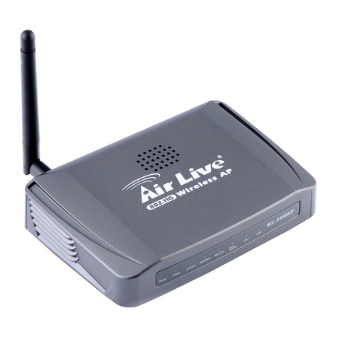
BDS DosaLink 540 User manual

User’s Manual 1/73
Ver. [E.1.1]
DosaLink – 540 Wireless LAN IEEE
802.11 a/b/g Access Point User’s Manual
Version E.1.1
Copyright statement
No part of this publication may be reproduced, stored in a retrieval system, or
transmitted in any form or by any means, whether electronic, mechanical, photocopying,
recording, or otherwise without the prior writing of the publisher.

User’s Manual 2/73
Ver. [E.1.1]
Table of Contents
1. Introduction............................................................................................................. 4
2. Features.................................................................................................................... 5
3. Specifications ......................................................................................................... 6
4. Exterior view............................................................................................................ 7
5. Installing the Hardware......................................................................................... 8
5.1. Before Installing............................................................................................. 8
5.2. Connecting the Cables................................................................................. 9
5.3. Configuration Information........................................................................... 9
5.4. Factory Default Setting................................................................................. 9
6. Configure the computer for sharing the Internet ........................................ 10
6.1. Configuration for Windows 2000 and XP .............................................. 10
6.1.1. Obtain an IP address automatically for DosaLink – 540 ........... 10
6.1.2. Confirm and Renew the IP address ................................................ 12
6.1.3. Assign the static IP address............................................................. 13
7. Communication between user’s PC and the DosaLink – 540.................. 15
8. Connect the Internet via the configuration window of DosaLink – 540 16
9. Configuration the DosaLink – 540................................................................... 21
9.1. ADSL (PPPoE) users................................................................................... 21
9.2. Cable and VDSL Users ............................................................................... 22
9.3. Static IP Users .............................................................................................. 23
9.4. Remove all the Network related Programs ........................................... 24
10. Network Connection Status .............................................................................. 24
11. Description the Menu of DosaLink – 540....................................................... 25
11.1. LAN Setup.................................................................................................. 25
11.2. Server.......................................................................................................... 26
11.3. Access Control......................................................................................... 27
11.4. Port Forwarding........................................................................................ 28
11.5. Static Routing ........................................................................................... 30
11.6. System ........................................................................................................ 30
11.7. Wireless Setup.......................................................................................... 32
11.8. nESA Setup................................................................................................ 34
11.9. Advanced ................................................................................................... 36
11.10. Wireless Distribution System (WDS).................................................. 37
11.11. MAC Filtering............................................................................................. 38
11.12. IEEE 802.1x................................................................................................ 39
11.13. Wi-Fi Protected Access (WPA)/ WPA2 (IEEE 802.11i).................... 41
11.14. Virtual Local Area Networks (VLAN)................................................... 43
12. Factory Resetting................................................................................................. 44
12.1. Resetting via the Web............................................................................. 44

User’s Manual 3/73
Ver. [E.1.1]
12.2. Hardware Reset ........................................................................................ 47
13. Configuration via Console................................................................................. 47
13.1. Connection................................................................................................. 47
13.2. Status.......................................................................................................... 49
13.3. LAN Setup.................................................................................................. 50
13.4. WAN Setup................................................................................................. 51
13.5. Server.......................................................................................................... 55
13.6. Access Control......................................................................................... 57
13.7. Port Forwarding........................................................................................ 58
13.8. Static Routing ........................................................................................... 60
13.9. Wireless Setup.......................................................................................... 61
13.9.1. Primary Setup ................................................................................... 62
13.9.2. Advanced Setup............................................................................... 65
13.9.3. WDS..................................................................................................... 66
13.9.4. MAC Filtering..................................................................................... 66
13.9.5. 802.1x.................................................................................................. 67
13.9.6. nESA Key Setup............................................................................... 69
13.9.7. VLAN.................................................................................................... 69
13.9.8. WPA/ WPA2 ....................................................................................... 70
Appendix I: Abbreviations and Acronyms............................................................ 72

User’s Manual 4/73
Ver. [E.1.1]
1. Introduction
Thank you for purchasing the DosaLink – 540 Wireless LAN Secure Access Point
(AP). This User’s Manual will help you to configure and operate the DosaLink – 540
Access Point.
The other bands exept ISM Band, 5150~5250MHz, shall be used at only Indoor.
The package you have received contains the following items:
-DosaLink – 540 Wireless LAN IEEE 802.11a/b/g Secure AP
-2 Antennas connected to DosaLink – 540 AP
-AC-DC Power Adapter, Ethernet Cable, and Serial Cable
-CD containing the User’s Manual
Note: if any items are missing, please contact your vendor.
FCC Caution: To assure continued compliance, any changes or modifications
not expressly approved by the party responsible for compliance could void the
user’s authority to operate this equipment.
This device complies with Part 15 of the FCC Rules. Operation is subject to the
following two conditions: (1) This device may not cause harmful interference, and
(2) this device must accept any interference received, including interference that
may cause undesired operation.
FCC RF Exposure Requirements: (Accoding as FCC Part 15.407(f))
The compliance with RF exposure requirements has been demonstrated for both
fundamental and unwanted emissions
This equipment must be installed and operated in accordance with provided
instructions and the antenna(s) used for this transmitter must be installed to
provide a separation distance of at least 20cm from all persons and must not be
co-located or operating in conjunction 20cm wth any other antenna or transmitter.
End-users and installers must be provide with antenna installation instructions
and transmitter operating conditions for satisfying RF exposure compliance.

User’s Manual 5/73
Ver. [E.1.1]
2. Features
Enhance security of your Wireless Local Area Network (WLAN) with the initiation of
the nDosa Enhanced Security Algorithm (nESATM). The novel concept of security
solution is applied to WLAN.
Introduce the novel security key management system - LinkAuthenticaTM – for
managing the security key of WLAN networks.
Simple installation and configuration:
-Supporting Secure Socket Layer (SSL) Web management (https://).
-Easy to control user interface and display.
-Easy to configure network with regard to user network environments (driving
Dynamic Host Configuration Protocol (DHCP) onto LAN interface).
-Enhanced security over wireless link (The nESATM is set as default).
Supporting Network Address Translation (NAT)
-Minimize the lowering throughput due to NAT by using high speed processing.
-Up to 253 users may be able to share the network simultaneously.
Strong phased security functions:
-The Firewall functioning of NAT is able to block an intrusion from any untrusted
external networks.
-By utilizing the Demilitarized Zone (DMZ) function, it can be served actively for
requesting outside information.
-The security policies can be established by using the Internet Protocol (IP)
Filtering and Media Access Control (MAC) Filtering functions.
-Complete WLAN security solution by using Wired Equivalent Privacy (WEP), Wi-
Fi Protected Access (WPA), IEEE 802.1x, nESA, and etc.
-Supporting IEEE 802.1x Extensible Authentication Protocol (EAP)-Message-
Digest algorithm 5 (MD5)/ Transport Layer Security (TLS)/ Tunneled Transport
Layer Security (TTLS).
Three 10/100 Mbps Ethernet Ports.
-Cable Auto Sensing (Auto-Medium Dependent Interface Crossover (MDIX))
Supporting Point-to-Point Protocol over Ethernet (PPPoE).
Supporting various Network Protocols.
Supporting Wireless Distribution System (WDS) and Bridge functions.
Supporting Simple Network Management Protocol (SNMP) V1, V2.

User’s Manual 6/73
Ver. [E.1.1]
3. Specifications
WAN Interface -10/100Base-TX Auto Negotiation 1 Port (RJ-45) Auto
MDIX
-IEEE802.3af Power Over Ethernet
LAN Interface -10/100Base-Tx Auto Negotiation 3 Port (RJ-45) Auto
MDIX
Wireless LAN Interface -IEEE802.11a/b/g
-Transmit Power:
less than 30 dBm (2.4GHz),
less than 30 dBm (5725~5825 MHz)
less than 17 dBm (5150~5250 MHz)
-Indoor : 70m , Outdoor : 300m
-Transmit Speed:1/2/5.5/6/9/11/12/18/24/36/54Mbps
Auto & Manual Selectable
Reset -Factory Default Value
LED Indicator -PWR, WAN, LAN1, LAN2, LAN3, DIAG, WLAN
Operation Environment -Ambient Operation Temperature: 0ºC to 40ºC
-Storage Temperature: -10ºC to 50ºC
-Maximum Altitude: 3000m
-Relative Humidity: 90% Non-Condensing
Power Requirement -DC 5V / 2A
-AC 90 ~ 260 V, 50 ~ 60Hz
Dimensions -W [ 190 ] , H [ 30.6 ] , D [ 125.3 ]
Protocol -IP, ARP, ICMP, UDP, TCP
-PPPoE, Telnet
-IP Static Routing & DHCP Server/Client/Relay
Security -nESA (256 bits)
-nESA with LinkAuthentica
-WEP (64/128 bits)
-WPA-PSK & WPA (TKIP/AES)
-WPA2-PSK & WPA2 (TKIP/AES)
Authentication -IEEE802.1x (MD5/TLS/TTLS)

User’s Manual 7/73
Ver. [E.1.1]
Wireless Function -Point to Point/Point to Multipoint Bridge & WDS
Firewall -NAT
-MAC Filtering, IP Filtering
Management -SNMP V1/2, Wireless & Ethernet MIB
-HTTPS(SSL)
-WEB Base Configuration
-Console Base Configuration
Table 1 DosaLink – 540 Specifications
4. Exterior view
Figure 1 DosaLink - 540 Top Views
PWR
Indicates the status of the power
•Off – the power is not connected
•On – the power is connected
DIAG
Indicates the operation status of AP
•Off – Normal operation
•On – Malfunction status

User’s Manual 8/73
Ver. [E.1.1]
WAN
Indicates the connection status of Wide Area Network (WAN) Link
•Off – The physical connection is not completed
•On – The physical connection is completed
•Blinking – The packets are sending and receiving with
normal connection
Port1
Port2
LAN
Port3
Indicates the connection status of Local Area Network (LAN) Link
•Off – The physical connection is not completed
•On – The physical connection is completed
•Blinking - The packets are sending and receiving with
normal connection
WLAN
Indicates the connection status of WLAN
•Off – Malfunction
•On – Normal operation
•Blinking - The packets are sending and receiving with
normal connection
Table 2 Indications of the Front side LED
Figure 2 DosaLink - 540 Back View
5. Installing the Hardware
5.1. Before Installing
The user’s MODEM should be plugged into the power after configuring the
DosaLink – 540.
In the case of an Automatic connection MODEM among Asymmetric Digital
Subscriber Line (ADSL) MODEM users, “Cable, VDSL” should be selected in the
“WAN Setup” menu on the DosaLink – 540’s configuration window.
The Automatic connection MODEM has built-in “user account” and “password”,
which are required to authenticate the PPPoE, so it may be able to connect to
the Internet without any connection program.

User’s Manual 9/73
Ver. [E.1.1]
5.2. Connecting the Cables
Connecting LAN port(s) of the Ethernet to WAN port of the DosaLink – 540.
Since WAN port of the DosaLink -540 have built-in AUTO DI/MDI function, either
a direct cable or cross cable can be used.
Connecting LAN port(s) of the DosaLink -540 to corresponding user’s PC.Since
LAN port of the DosaLink – 540 have built-in AUTO MDI/MDIX function, either a
direct cable or cross cable can be used.
Figure 3 Example of connecting cables
5.3. Configuration Information
The following information is required for configuring the DosaLink -540:
Type of broadband (ADSL, VDSL, Cable, Static IP).
“User Name (Login Name)” and “Password” for ADSL user.
In the case of a Static IP Address: IP Address, Subnet Mask, Gateway, DNS
Server Address, etc.
5.4. Factory Default Setting
LAN interface IP: 192.168.1.1
DHCP: Server
Assigned IP Address of DHCP Server: 192.168.1.2 ~ 254
WAN: Cable, VDSL/ Dynamic IP

User’s Manual 10/73
Ver. [E.1.1]
SSID: nDOSA
Channel: 6
User ID: root
User Password: admin
Wireless Encryption: nESA with Default Key
6. Configuring the computer for sharing the Internet
For sharing the Internet through the DosaLink – 540, the computer should be
configured while the communication between the user’s PC and DosaLink – 540
is normal.
Since LAN IP of the DosaLink – 540 is 192.168.1.1, the user’s PC should have
the following network IP address – 192.168.1.2 ~ 254 – for connecting to the
DosaLink – 540.
There are two ways to assign IP Address to user’s PC. First, the user’s PC
obtains an IP address automatically from the Dosalink – 540 assigned IP address.
Second, the IP address can be assigned by the user. However, a static IP
address should be assigned for operating servers such as Web, FTP, etc.
Configuring the user’s PC may vary depending on the Operating System (OS)
being utilized. This manual is written for users of Windows 2000 and XP.
6.1. Configuration for Windows 2000 and XP
6.1.1. Obtain an IP address automatically for DosaLink – 540
1. “Control Panel” => “Network Connections” => “Local Area Connection” =>
“General” => click “Properties”, and then Figure 4 pops up. In this “Local Area
Connection Properties” window, select “TCP/IP” and click “Properties”.
2. In the “Internet Protocol (TCP/IP) Properties” window, select “obtain an IP
address automatically” and “obtain DNS server address automatically” as
shown in Figure 5. Then, click “OK” to save the configuration.

User’s Manual 11/73
Ver. [E.1.1]
Figure 4 “Local Area Connection Properties” Window
Figure 5 “Internet Protocol (TCP/IP) Properties” Window

User’s Manual 12/73
Ver. [E.1.1]
6.1.2. Confirm and Renew the IP address
The saved configuration information may be confirmed by using the “ipconfig”
command in the DOS window.
1. Select “Start” => “Run” and input “cmd”. Then, click “OK” to execute the DOS
window.
Figure 6 “Run” Window
2. The IP address, Subnet Mask, and Gateway that are assigned automatically
should be confirmed with inputting the command “ipconfig” on the DOS
window. If it is normal, then the IP address should be assigned
“192.168.1.xxx” as shown in Figure 7.
Figure 7 DOS Window (“ipconfig”)
3. If the assigned IP address is outscope of “192.168.1.xxx, then it should be
renewed by “ipconfig /release” and “ipconfig /renew” commands as shown in
Figure 8.

User’s Manual 13/73
Ver. [E.1.1]
Figure 8 DOS WIndow (ipconfig / release & ipconfig /renew)
4. If the assigned IP address is an outscope of “192.168.1.xxx” or it has failed to
get an IP address even though the above steps for getting an IP address
were excuted, then the static IP address should be assigned by the user with
regard to the following section.
6.1.3. Assign the static IP address
This section explains how to assign the static IP address to the user’s PC when
the DosaLink – 540 cannot assign an IP address to the user’s PC or a server is
operating on the network.
1. “Control Panel” -> “Network Connections” -> “Local Area Connection” ->
“General” -> click “Properties”, and then Figure 9 pops up. In this “Local Area
Connection Properties” window, select “TCP/IP” and click “Properties”.
2. In the “Internet Protocol (TCP/IP) Properties” window, select “Use the
following IP address” and “Use the following DNS server addresses” as
shown in Figure 10. Then, input the correct addresses and click “OK” to save
the configuration.

User’s Manual 14/73
Ver. [E.1.1]
Figure 9 “Local Area Connection Properties” window
3. If several user’s PCs need to be assigned IP addresses, then the information
for Subnet Mask, Gateway, and DNS server should be the same and the IP
address should be selected between 192.168.1.2 and 192.168.1.254.

User’s Manual 15/73
Ver. [E.1.1]
Figure 10 “Internet Protocol (TCP/IP) Properties” window
7. Communication between user’s PC and the DosaLink – 540
The communication between the user’s PC and the DosaLink - 540 should be
confirmed before configuring the PC by utilizing the configuration window of the
DosaLink – 540. For this purpose the “ping” command can be used.
“Start” => “Run”, input “cmd” and press “OK”. The DOS window will be open.
Once performed “ping 192.168.1.1”, should appear as shown as Figure 11. If it
does not appear, then the sequence should be performed again after pressing
“reset”, which is located on the back of the DosaLink -540, and rebooting the
user’s PC.

User’s Manual 16/73
Ver. [E.1.1]
Figure 11 “ping” in the DOS window
8. Connect the Internet via the configuration window of DosaLink – 540
1. First, run the web browser to connect to the Internet. However, it is not
connected to the Internet because the DosaLink – 540 is not configured yet. On
the web browser’s menu, select “tools” => “Internet options...”.
Figure 12 “Internet Option”
2. To Delete the temporary Internet Files in the Internet options window click on
“Delete Cookies...” and “Delete Files...” Then select “Connections”.

User’s Manual 17/73
Ver. [E.1.1]
Figure 13 “Delete Cookies” & “Delete Files”
3. At “Dial-up and Virtual Private Network settings” menu, select “Never dial a
connection” then click “LAN Settings...” as shown in Figure 14.

User’s Manual 18/73
Ver. [E.1.1]
Figure 14 “Dial-up and Virtual Private Network settings”
4. In the “Local Area Network (LAN) Settings” window, remove the check marks (V)
as shown in Figure 15 and select “OK” to save the configurations.

User’s Manual 19/73
Ver. [E.1.1]
Figure 15 “LAN Settings” window
5. After configuration enter https://192.168.1.1 into the “Address” window of web
browser as shown in Figure 16.
Figure 16 https://192.168.1.1
6. Since the SSL is implemented to enhance the security, if the message as shown
in Figure 17 appears, then select “Yes”.

User’s Manual 20/73
Ver. [E.1.1]
Figure 17. SSL Message
7. The Default “ID” and “Password” to connect to this web page, shown in Figure
18, are ‘root’ and ‘admin’, respectively.
Figure 18 Default User ID and Password
8. If it connects, as shown in Figure 19, the initial page to manage the DosaLink –
540 wil appear.
Table of contents
Popular Wireless Access Point manuals by other brands

NETGEAR
NETGEAR ProSafe Premium WNDAP620 Reference manual
Aerohive
Aerohive AP250 user guide
D-Link
D-Link DWL-2230AP - xStack - Wireless Access Point Quick installation guide
Lindsay
Lindsay LBN200 RFoG ONU user manual
LEGRAND
LEGRAND DA1101 Instruction/installation sheet
CommScope
CommScope RUCKUS H350 Quick setup guide
