BE Ag & Industrial DD400 Application guide
PURCHASE DATE MODEL NO. SERIAL NUMBER
DEALER
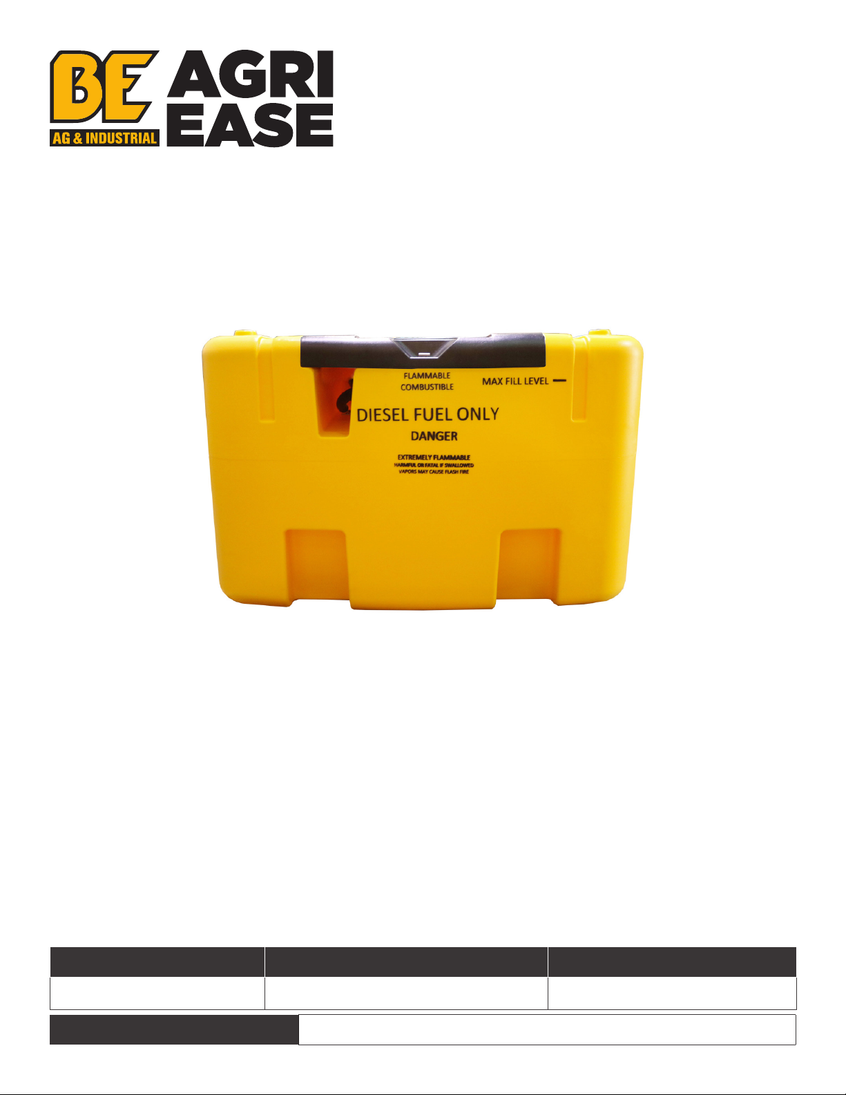
DIESEL TRANSFER
TANK
DD400
OPERATIONS & PARTS MANUAL
FOR MODELS:
• DD400

TABLE OF CONTENTS
3INTRODUCTION & SAFETY
7OPERATION
8TRANSPORT
9SET UP
11 MAINTENANCE
13 EXPLODED VIEW & PARTS LIST
DD400 USER MANUAL 3
Thank you for purchasing our product. Manufactured to a high standard, this product will, if used according
to these instructions, and properly maintained, give you years of trouble-free performance.
IMPORTANT: PLEASE READ THESE INSTRUCTIONS CAREFULLY. NOTE THE SAFE OPERATIONAL
REQUIREMENTS, WARNINGS & CAUTIONS. USE THE PRODUCT CORRECTLY AND WITH CARE FOR THE
PURPOSE FOR WHICH IT IS INTENDED. FAILURE TO DO SO MAY CAUSE DAMAGE AND/OR PERSONAL
INJURY AND WILL INVALIDATE THE WARRANTY. KEEP THESE INSTRUCTIONS SAFE FOR FUTURE USE.
SPECIFICATION
Model No: DD400
Voltage: 12V
Current: 15A
Power: 180W
Tank capacity: 400l
Flow rate: 20l/min
Duty cycle: 30 mins pm / 30 mins o
Dimensions (W x D x H): 1100 x 800 x 720mm
Nett Weight: 43.16kg
SAFETY
WARNING!
This tank must ONLY be used for diesel fuel.
• Place the tank on a flat surface before filling.
• Secure the tank to strong points with ratchet straps before transporting in or on a vehicle.
• Maintain the pump in good condition (use an authorized service agent).
• Replace or repair damaged parts. Use recommended parts only. Non authorized parts may be dangerous
and will invalidate the warranty.
• Keep the pump clean for best and safest performance.
• Ensure the power supply (vehicle battery) corresponds with the requirements of the pump (12V DC).
• Disconnect from battery when not in use.
• Wear protective gloves, and protective clothing when working around fuel.
• Keep children and unauthorized persons away from the working area.
• DO NOT place the tank near any heat source.
• DO NOT start or stop the pump by connecting or disconnecting the battery clamps.
• DO NOT allow the unit to get wet.
• DO NOT operate the pump with wet hands.
• DO NOT use the pump where explosive or flammable vapours may be present.
• DO NOT tamper with the pump connections.
INTRODUCTION
Manufactured of LLDPE for the safe transportation and dispensing o f diesel fuel when supplying on site
equipment. Complies to ADR 1.1.3.1.C for exemption from requirements of ADR regulations. Supplied with
a 12V electric pump, 4mtr electric cable and clamps and a 4mtr delivery hose with automatic fuel nozzle.
Can be safely secured and transported on a pick-up truck or van, using grooves for tie-down straps and 6
handles for positioning. Supplied with lockable cover. Not suitable for petrol.
4 DD400 USER MANUAL
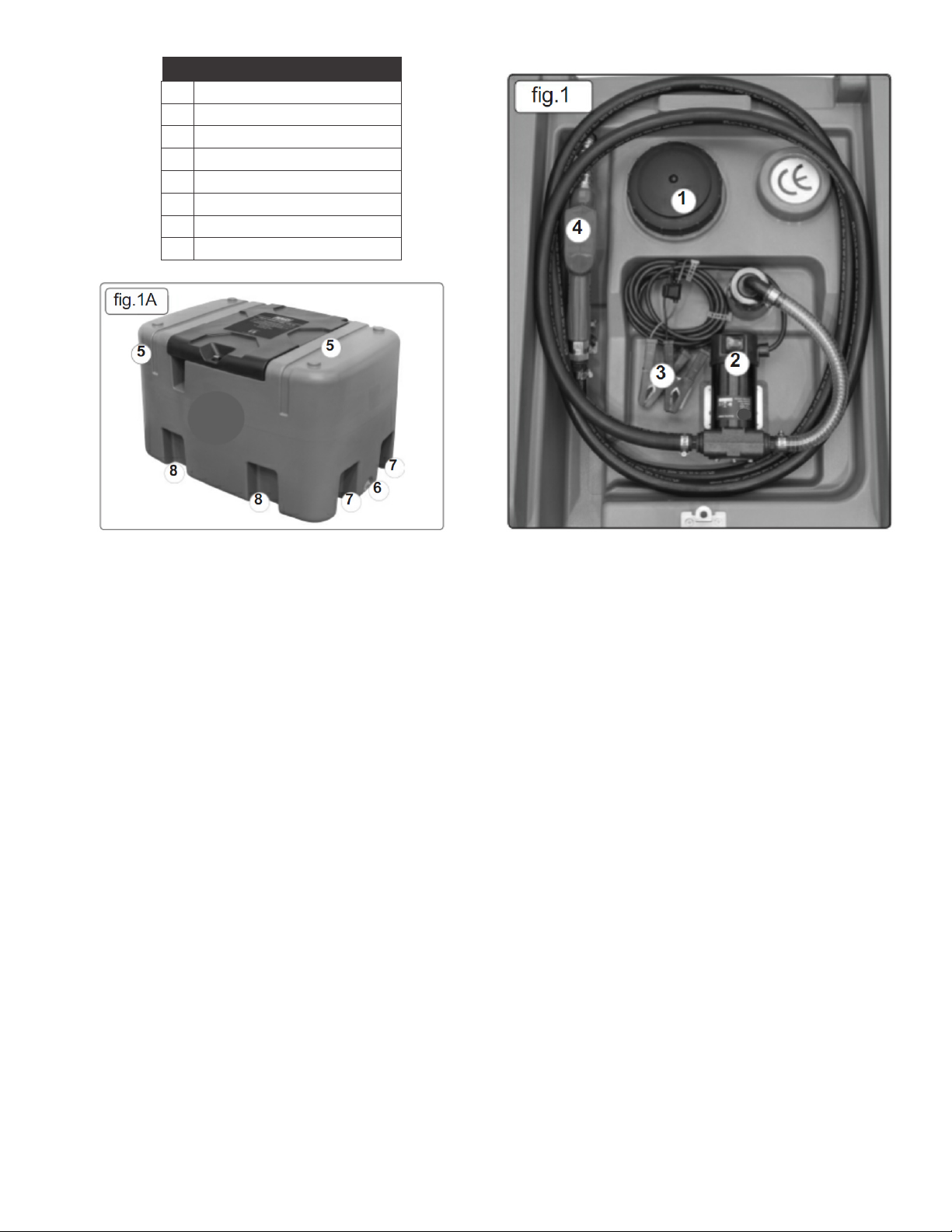
KEY (FIG 1 & FIG 1A)
1 Breather Lid
2 Pump On/O Switch
3 Battery Clips
4 Automatic Fluid Nozzle
5 Securing Strap Locations
6 Vent Plug
7 Fork Locations
8 Moulded Hand Holds
OPERATION
TRANSPORT
Move the empty tank assembly with two persons using the hand holds moulded into the base of the unit
(fig.1A.8).
Move by forklift truck using the fork locations shown in (fig.1A.7). Ensure that the filler (fig.1A.1) is closed
before moving.
Secure the tank to the carrying vehicle by ratchet straps. Locations for the straps are moulded into the tank
(fig.1A.5).
FILLING
DO NOT run the pump without fuel in the tank. To do so will damage the pump’s internal components and
will invalidate your warranty.
The tank is filled by unscrewing the filler (fig.1.1) in an anticlockwise direction. Refit the filler cap immediately
after filling.
WARNING take care not to overfill the tank.
FUEL DISPENSING
Before connecting to a battery, make sure that the pump switch (fig.5.2) is in the ‘o’ (O) position. Connect
the battery clips to the 12V battery, observing correct polarity (red clamp to +ve terminal, black clamp to -ve
terminal).
Switch the pump switch to the ‘on’ (I) position.
Unwind sucient hose and place the nozzle (fig.4) in the receiving tank and pull the trigger (fig.4). Delivery
will commence and continue until the trigger is released.
The trigger can be locked in one of three positions by engaging the latch (fig.4) to hold the trigger open. DO
NOT leave the nozzle unattended with the trigger latched open.
Slight pressure on the trigger will release the latch.
When the level in the receiving tank reaches the nozzle, delivery will stop automatically.
When delivery is complete, switch o the pump. Ensure the hose is wound into its housing on the tank and
that the nozzle is secured in its storage place.

DD400 USER MANUAL 5
DO NOT operate the pump continuously for more than 30 minutes. The duty cycle of the unit is 30 minutes,
after which the motor must be left to cool down for a further 30 minutes.
DO NOT run the unit for more than 2-3 minutes with the delivery nozzle closed.
MAINTENANCE
The pump contains no user-serviceable parts.
Repairs should only be undertaken by competent persons.
Check the integrity of all the hose connections periodically. If any leakage is evident, strip the joint and wind
PTFE tape around the male thread.
Check all electrical connections and cables for wear and damage. Rectify any faults found.
Keep clean, especially the dispenser nozzle.
Clean with a damp, soapy cloth.
DO NOT use abrasive or solvent cleaners.
4. OPERATION
4.1. TRANSPORT
4.1.1. Move the empty tank assembly with two persons using the hand holds moulded into the base of the unit (fig.1A.8).
4.1.2. Move by forklift truck using the fork locations shown in (fig.1A.7). Ensure that the filler (fig.1A.1) is closed before moving.
4.1.3. Secure the tank to the carrying vehicle by ratchet straps. Locations for the straps are moulded into the tank (fig.1A.5).
4.2. FILLING
4.2.1. DO NOT run the pump without fuel in the tank. To do so will damage the pump’s internal components and will invalidate your warranty.
4.2.2. The tank is filled by unscrewing the filler (fig.1.1) in an anticlockwise direction. Refit the filler cap immediately after filling.
WARNING take care not to overfill the tank.
4.3. FUEL DISPENSING
4.3.1. Before connecting to a battery, make sure that the pump switch (fig.5.2) is in the ‘off’ (O) position. Connect the battery clips to the
12V battery, observing correct polarity (red clamp to +ve terminal, black clamp to -ve terminal)
4.3.2. Switch the pump switch to the ‘on’ (I) position.
4.3.3. Unwind sufficient hose and place the nozzle (fig.4) in the receiving tank and pull the trigger (fig.4). Delivery will commence and
continue until the trigger is released.
4.3.4. The trigger can be locked in one of three positions by engaging the latch (fig.4) to hold the trigger open. DO NOT leave the nozzle
unattended with the trigger latched open.
4.3.5. Slight pressure on the trigger will release the latch.
4.3.6. When the level in the receiving tank reaches the nozzle, delivery will stop automatically.
4.3.7. When delivery is complete, switch off the pump. Ensure the hose is wound into its housing on the tank and that the nozzle is
secured in its storage place.
4.3.8. DO NOT operate the pump continuously for more than 30 minutes. The duty cycle of the unit is 30 minutes, after which the motor must
be left to cool down for a further 30 minutes.
4.3.9. DO NOT run the unit for more than 2-3 minutes with the delivery nozzle closed.
5. MAINTENANCE
5.1.
5.2.
5.3.
5.4.
-
x
The pump contains no user-servicable parts.
Repairs should only be undertaken by competent
persons.
Check the integrity of all the hose connections
periodically. If any leakage is evident, strip the
joint and wind PTFE tape around the male thread.
Check all electrical connections and cables for wear
and damage. Rectify any faults found.
Keep clean, especially the dispenser nozzle.
Clean with a damp, soapy cloth.
DO NOT use abrasive or solvent cleaners.
fig.3
fig.41
55
fig.5
87
87
2
ENVIRONMENT PROTECTION
Recycle unwanted materials instead of disposing of them as waste. All tools, accessories and packaging should be sorted, taken to
a recycling center and disposed of in a manner which is compatible with the environment. When the product becomes completely
unserviceable and requires disposal, drain any fluids (if applicable) into approved containers and dispose of the product and fluids
according to local regulations.
Note: It is our policy to continually improve products and as such we reserve the right to alter data, specifications and component parts without prior notice.
Important: No Liability is accepted for incorrect use of this product.
Warranty: Guarantee is 24 months from purchase date, proof of which is required for any claim.
ENVIRONMENT PROTECTION
Recycle unwanted materials instead of disposing of them as waste. All tools, accessories
and packaging should be sorted, taken to a recycling center and disposed of in a manner
which is compatible with the environment. When the product becomes completely
unserviceable and requires disposal, drain any fluids (if applicable) into approved containers
and dispose of the product and fluids according to local regulations.
Note: It is our policy to continually improve products and as such we reserve the right to
alter data, specifications and component parts without prior notice.
Important: No Liability is accepted for incorrect use of this product.
Warranty: Guarantee is 24 months from purchase date, proof of which is required for any
claim.
6 DD400 USER MANUAL
Item
Part No.
Description
Item
Part No.
Description
1
DD400.01
Vent Plug
2
DD400.02
Tank 400L
11 DD400.11 Breathing Cap
12 MSP610.S
Machine screw pan Head Phillips M6 x 10mm
3
DD400.03
3/4" Connection Hose
13
DD400.13 Nozzle Holder
4
DD400.04 Lower Seal for Suction Elbow 14 DD400.14
Tank Lid Lock Holder
5
DD400.05 Hose Clip
15
DD400.15 Electric Pump 12V
6
DD400.06 Suction Elbow 16 DD400.16
Bracket for Electric Pump
7
DD400.07
Upper Seal for Suction Elbow
17 DD400.17
Automatic fluid Nozzle
8
DD400.08
Suction Cap
18
DD400.18 Delivery Hose 4 mt
9
DD400.09 Level Gauge 19 DD400.19 Filter
10
DD400.10
Tank Lid
20 DD400.20 Hose
NOTE: It is our policy to continually improve products and as such we reserve the right to alter data, specifications and component parts without prior notice.
IMPORTANT: No liability is accepted for incorrect use of product. Spare parts must be fitted by a competent person
WARRANTY: Guarantee is 24 months from purchase date, proof of which will be required for any claim.
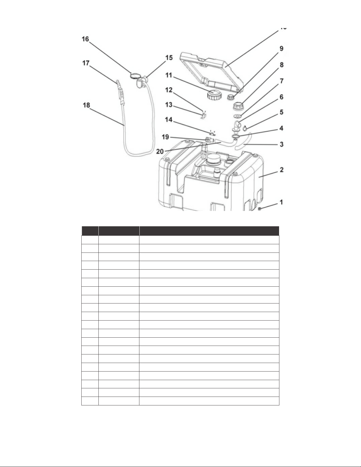
Parts List:
Portable Diesel Tank 12V
Model No: DD400
REF PART NUM DESCRIPTION
1 DD400.01 Vent Plug
2 DD400.02 Tank 400L
3 DD400.03 3/4" Connection Hose
4 DD400.04 Lower Seal for Suction Elbow
5 DD400.05 Hose Clip
6 DD400.06 Suction Elbow
7 DD400.07 Upper Seal for Suction Elbow
8 DD400.08 Suction Cap
9 DD400.09 Level Gauge
10 DD400.10 Tank Lid
11 DD400.11 Breathing Cap
12 MSP610.S Machine screw pan Head Phillips M6 x 10mm
13 DD400.13 Nozzle Holder
14 DD400.14 Tank Lid Lock Holder
15 DD400.15 Electric Pump 12V
16 DD400.16 Bracket for Electric Pump
17 DD400.17 Automatic fluid Nozzle
18 DD400.18 Delivery Hose 4 mt
19 DD400.19 Filter
20 DD400.20 Hose
EXPLODED VIEW & PARTS LIST
NOTE: It is our policy to continually improve products and as such we reserve the right to alter data,
specifications and component parts without prior notice.
IMPORTANT: No liability is accepted for incorrect use of product. Spare parts must be fitted by a competent
person
WARRANTY: Guarantee is 24 months from purchase date, proof of which will be required for any claim.

DD400 USER MANUAL 7

8 DD400 USER MANUAL
PHONE: 604-850-7770
FAX: 604-850-7774
TOLL FREE PHONE: 1-877-588-3311
TOLL FREE FAX: 1-800-665-7334
BRABEREQ.COM
WGSALES@BRABEREQ.COM
Table of contents
Popular Tank Equipment manuals by other brands

Liqua
Liqua H-Flex Steam Liner instruction manual

Field Tuff
Field Tuff FTF-10GOR owner's manual

Global Water Solutions
Global Water Solutions PressureWave Installation and operation manual

Grundfos
Grundfos El.stirrer f.60l tank Installation and operating instructions

ENCON
ENCON SAF-T-TUB 01052539 Installation, operation and maintenance manual

Amtrol
Amtrol THERM-X-TROL ST-5C Series Installation & operation instructions

