V20240125 •Page 2 of 9Model: FST
PEOPLE OR OBJECTS CAN BE HURT OR DAMAGED IF THIS UNIT IS NOT USED CORRECTLY!
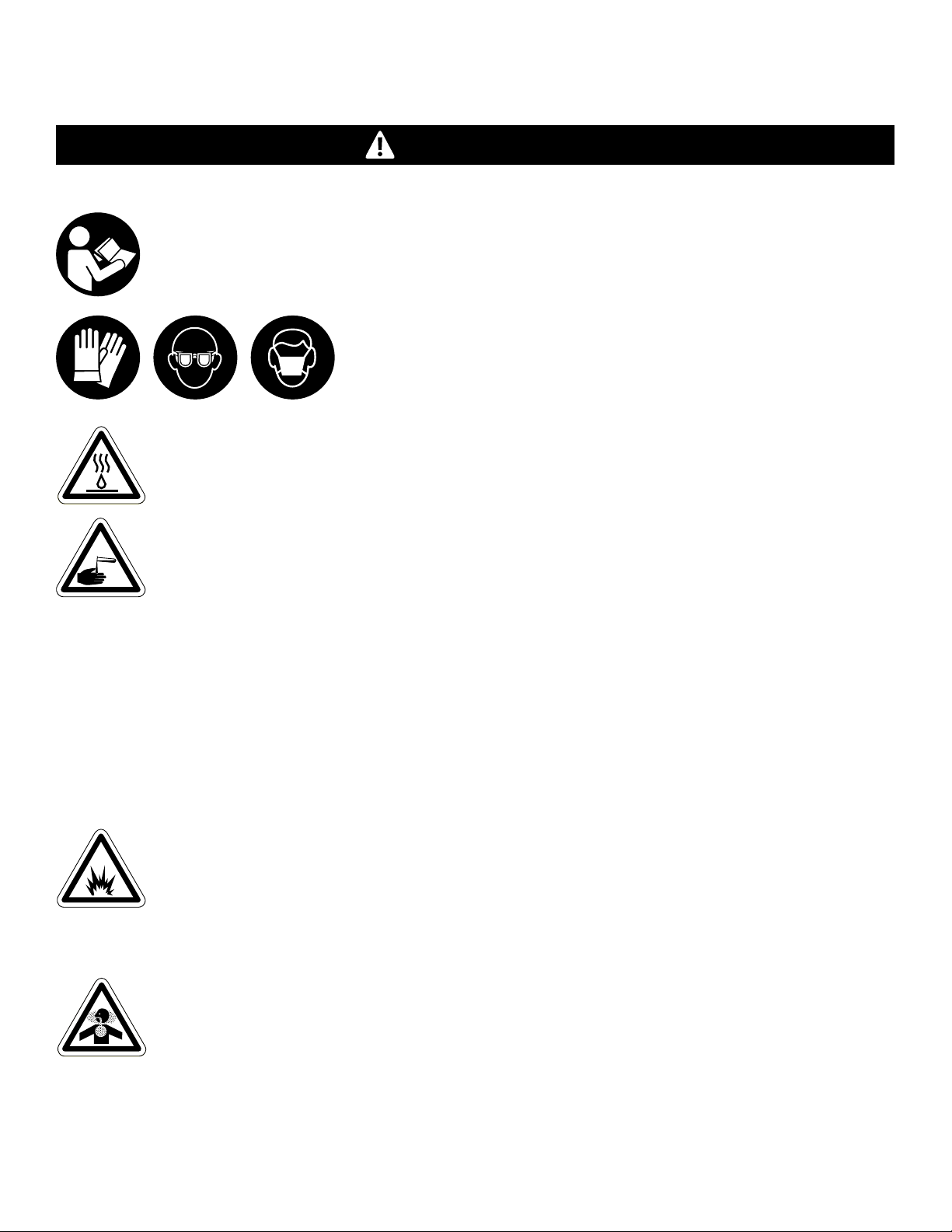
Failure to read all the instructions before operating the unit may result in personal injury or death from
the improper use or the chemical solution. Anyone handling, operating or using the unit must read and
understand the instructions in the manual. The buyer assumes all responsibility for safety and proper
use in accordance with the instructions.
Using or servicing the unit without appropriate personal protective
equipment (PPE) may result in serious injury such as burns, rashes, eye,
throat or lung damage and death. Always wear PPE as indicated in the
Safety Data Sheet (SDS) when using or servicing the unit. Protect eyes, skin,
and lungs against drifting spray.
Chemical solutions may pose a health risk and death if they contact the skin or eyes, are inhaled
or swallowed. Always read and follow all chemical safety precautions and handling instructions
provided by the chemical manufacturer and the SDS associated with the chemical solution before
using the unit.
Pressure within the equipment may cause an unexpected release of the chemical solution and
cause serious injury such as burns, rashes, eye damage, throat or lung damage and death.
Always depressurize and clean the unit after each use. Release any remaining air pressure by opening
the discharge ball valve. Never leave the unit unattended while pressurized.
Using the unit with fluid temperatures above 100°F (37.8°C) may result in scalding, burns, serious injury
or death. DO NOT use a solution with a temperature above 100°F (37.8°C).
Operating the unit when damaged or leaking may result in exposure to chemical solutions, serious
injury or death. Never use the unit if it is damaged or leaking.
Never open ball valves with chemical in the tank, unless the ball valves are connected to an
appropriate location for chemical discharge. Never point the discharge valves at yourself, another
person, or any object you do not want covered in chemical. Never operate unit without the lid on.
Do not use the unit if an overflow hose is not installed. If chemical flows from the overflow port, shut
down the unit immediately and correct the problem before proceeding.
Using incoming air pressure exceeding 80 psi (5.5 bar) may result in pressure buildup, explosion,
serious injury or death. DO NOT exceed 80 psi (5.5 bar) incoming air pressure when operating
the unit.
Use of hydrocarbons and flammable products may result in explosions, fire and serious injury or death.
Never use hydrocarbons or flammable products with the unit.
Mixing an alkaline with an acid may result in a chemical reaction. Overheating of the mixture may
cause it to splatter caustic compounds or release hazardous fumes, gas and vapors. Always flush
the unit with fresh water thoroughly when switching from an alkaline to an acid or an acid to
an alkaline.
WARNING
Safety