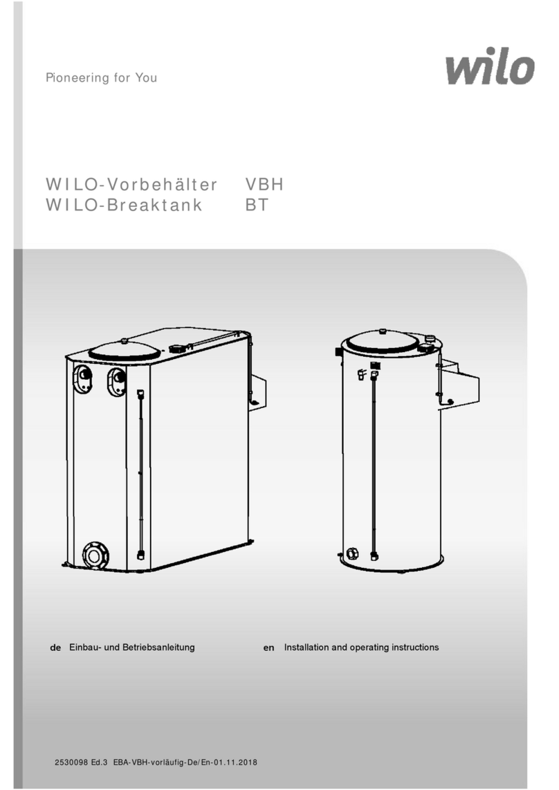
AQUATECH AquaBreak AB5 Firmware update

INSTRUCTIONSFOR
0. GENERALSAFETYINFORMATION,WARNINGS&CAUTIONS
1. INSTALLATION
2.THEUSER
3. SERVICING
4. DISPOSAL
AQUABREAKAB5BREAKTANK&PUMPSET
FORBACKFLOWPROTECTIONTOFLUIDCATEGORY5
ISSUE318/07/2017
HeadOffice:AGMHouse,LondonRd,Copford,Colchester,EssexCO61GTUK
Tel:01206215121Email:aftersales@agm‐plc.co.uk
ManchesterOffice:Unit10,WheelForgeWay,AshburtonRoadWest,Manchester.M171EH
Tel:01612264727Email:aftersales@agm‐plc.co.uk

Page|2
AquaTech-Pressmain Instruction Manual\AquaBreak
Thesepumpsetsareusedforincreasingthesupplypressureofcoldpotablewaterwhilstalsoprovidingback
flowprotectiontofluidcategory5.
CONTENTS
0. GENERAL SAFETY INFORMATION .............................. 3
0.1WARNINGS .................................................................................................... 4
0.2CAUTIONSFORINSTALLATION ........................................................................ 4
0.3CAUTIONSFOROPERATION/USER ................................................................... 6
0.4CAUTIONSFORMAINTENANCE ....................................................................... 6
1.
INSTALLATION INSTRUCTIONS ........................................................... 7
1.1ADDITIONALWARNINGS ............................................................................................... 7
1.2ADDITIONALCAUTIONS ................................................................................................ 7
1.3PROCEDURE ................................................................................................................. 7
1.3.1OFF‐LOADINGATSITE ............................................................................................ 7
1.3.2LOCATION ............................................................................................................ 8
1.3.3FIXING .................................................................................................................. 8
1.3.4PIPEWORK ............................................................................................................ 9
1.3.5FLOWTHROUGHVESSELS .................................................................................... 10
1.3.6ELECTRICAL ......................................................................................................... 10
2.
USER INSTRUCTIONS ......................................................................... 12
2.1CUSTOMERASSURANCE ............................................................................................. 12
2.2COMMISSIONING ....................................................................................................... 13
2.3OPERATINGINSTRUCTIONS ......................................................................................... 14
2.3.1ADDITIONALWARNINGS ...................................................................................... 14
2.3.2ADDITIONALCAUTIONS ....................................................................................... 14
2.3.3NORMALOPERATION .......................................................................................... 14
2.3.4TROUBLESHOOTINGGUIDE ................................................................................. 15
2.4MAINTENANCEINSTRUCTIONS .................................................................................... 16
2.4.1ADDITIONALCAUTIONS ....................................................................................... 16
2.4.2PROCEDURE ........................................................................................................ 16
3.
SERVICING ........................................................................................... 17

AquaBreakSeries
Page3of18
AquaTech-Pressmain Instruction Manual\AquaBreak
3.1MAINTENANCEANDCAREOFYOUREQUIPMENT ......................................................... 17
3.2LEGALREQUIREMENTS ............................................................................................... 17
3.3SERVICECONTACTS .................................................................................................... 17
4.
DISPOSAL ............................................................................................. 17
EU DECLARATION OF CONFORMITY ...................................................... 18
OPERATING PARAMETERS ...................................................................... 18
0.GENERALSAFETYINFORMATION
Theseinstructionsareintendedfortheinstaller/operator/user/maintenanceofthisequipmentand
mustbekeptwiththeequipment,forthelifeoftheequipmentandmadeavailabletoallpersons.
PleasereadGENERALSAFETYINFORMATION0.0,WARNINGS0.1andCAUTIONS0.2,0.3&0.4
beforedoinganythingelse,andthenfollowthemcarefully.
Theunitmustonlybeinstalled/operated/used/maintainedbyacompetentperson;Acompetent
personissomeonewhoistechnicallycompetentandfamiliarwithsafetypracticesandthehazards
involved.
HydraulicAccumulators/ExpansionVesselsinstalledaspartof/inconjunctionwiththisequipment,
withPressurexVolumeabove250Bar‐litres,requireregularformalinspectionbyacompetent
person.ThisisaLegalRequirementunderthe“PressureSystemsSafetyRegulations”(PSSR)and
theOwner/Usershouldbemadeawareoftheirresponsibilityforthis.(seesection3.Servicing).
Failuretoinstall/operate/use/maintaintheequipmentasrecommendedbelowcouldcause
damagetotheequipmentanyanythingsubsequentlyconnectedtoit,andinvalidatethewarranty
providedbyAquaTech‐Pressmaintothebuyer.
Anydamagecausedtotheequipmentbymisapplication,mishandlingormisusecouldleadtorisk
ofElectrocution,Burns,Fire,Floodingorinjurytopeopleorpropertydependentuponthe
circumstancesinvolved.
Thisequipmentcontainsmoving/rotatingpartsthatmustremainguarded.Removaloformissing
guardscouldleadtoseriouspersonalinjury.
Thisequipmentautomaticallyrestartsafterapowerinterruption.
Weacceptnoresponsibilityorliabilityforanyconsequencesordamage/lossesdueto
misapplication,mishandlingormisuseoftheequipment.
Itshouldbenotedthattheassemblyofpressureequipmentonsiteundertheresponsibilityofthe
user(orhisrepresentative)isnotsubjecttothePressureEquipmentDirective97/23/EC.(National
legislationcoveringassemblyonsitewillapply)
Thelatestversionofthisinstructionmanualwithuptodatesafetyinformationcanbedownloaded
fromourwebsiteatwww.aquatechpressmain.co.uk

AquaBreakSeries
Page4of18
AquaTech-Pressmain Instruction Manual\AquaBreak
0.1 WARNINGS
0.1.1 Donottouchanylivepartsforatleast5minutesafterswitchingofftheelectricitysupply.Failureto
observethiswillconstituteasevereElectricshockand/orBurnshazardandmaybelethal.
0.1.2 Theequipmentisonlysuitableforearthreferencedsuppliesandmustbepermanentlyearthedto
avoidElectricshockhazard.
0.1.3 Metalparts(e.g.heatsinks)mayreachtemperaturesof90degreescentigradeandwillconstitutea
Burnshazard.
0.1.4 Theequipmentmustnotbepressurisedbeyondthemaximumworkingpressureasstatedon
pumps/pipework/vessels/controlpanelotherwiseseriousmechanicaldamage/destructioncould
occurcausinginjurytopeopleorproperty.
0.1.5 Theequipmentmustnotbeheated/chilledbeyondthemaximum/minimumworkingtemperature
asstatedonpumps/pipework/vessels/controlpanelotherwiseseriousmechanical
damage/destructioncouldoccurcausinginjurytopeopleorproperty.
0.1.6 Anydamagetoequipment,pumpset,vessels,pipeworkorsystemcomponentscausedby
misapplication,mishandlingormisusecouldleadtoElectricshockhazard,Burnshazard,Firehazard,
Floodinghazardorcauseinjurytopeopleorproperty.
0.1.7 Thisequipmentmaycontainmoving/rotatingpartsthatmustremainguarded.Removalofor
missingguardscouldleadtoseriouspersonalinjury.
0.1.8 Pressurevesselsmustneverbedisassembledwhilstinuse,theycontainhighpressureair/gas
chargewhichcouldcauseinjurytopeopleorproperty.
0.1.9 Ensurethebase/foundation/plinth/walltowhichtheequipmentistobeattachedissufficiently
strongenoughtocarrytheentiremassoftheequipmentincludingthewaterthatitwillcontain
underworst‐casefaultconditions.E.g.fullysaturatedpressurevesselwithnoaircharge,breaktank
fulltooverflowing,etc.Failuretoobservethiscouldcauseseriousmechanicaldamage/destruction
resultingininjurytopeopleorproperty.
0.1.10 Thisequipmentcontainsafluidwhichmayundercertaincircumstancesleak/drip/sprayfluid(e.g.
servicing,repairormalfunction).Ensureanyfluiddischargewillnotcausedamagetothe
surroundingsbytakingappropriateaction.E.g.installinaplacethatwillnotbedamagedbyleakage
orinstallinabundedareawithadequatedrainage.
0.2 CAUTIONSFORINSTALLATION
0.2.1 READGENERALSAFETYINFORMATION0.0,WARNINGS0.1andCAUTIONS0.2,0.3&0.4
0.2.2 Theunitshouldonlybeinstalled/operatedbyacompetentperson;Acompetentpersonissomeone
whoistechnicallycompetentandfamiliarwithsafetypracticesandthehazardsinvolved.
0.2.3 Donotliftthepumpsetbypipework.Liftthepumpsetbythecontainerpalletusingapallet/forkliftor
cranebypassingstropsunderneaththeskidusingaspreaderbar.Failuretoutilisethesefacilitieswill
resultindamagetothepumpset.
0.2.4 Storeinadryplacetoavoiddampconditionsdeterioratingtheequipment.
0.2.5 Protectagainstdirt,damageandfrost.Itisabsolutelyessentialthatnoforeignmattersuchaspipe
threadswarf,weldingslag,gritorstonesareallowedtoentertheset.Debrisofthistypecancause
severedamagetothemechanicalseals,diaphragmsandimpeller.Frost/freezingwilldamage
pumps/pipeworkandcontrolpanelcomponents.
0.2.6 Theequipmentisonlysuitableforinstallationinaclean,dustfreeindoorenvironment,withadequate
protectionfromheatandfrost,andsufficientventilationtoensurecoolingofthemotors.Ambientair
temperatureshouldbebetween5and40degreescentigrade,non‐condensating.Operationoutsideof
theseconditionscouldseriouslydamagetheequipment.

AquaBreakSeries
Page5of18
AquaTech-Pressmain Instruction Manual\AquaBreak
0.2.7 Iftheequipmentweretobestoredortakenoutofserviceforaperiodoftime(e.g.1weekormore),
thenwewouldrecommenddrainingtheequipmentofallwater/liquid(withdueregardtoanylocal
regulations)topreventfrostdamagetocomponents.Whenrestartingisrequiredwewould
recommendcommissioningbyourauthorisedserviceagent.
0.2.8 Ensurethebase/foundation/plinth/walltowhichtheequipmentistobeattachedhassufficientmass
comparedtotheequipment,inordertoavoidnoise/vibrationtransmission.E.g.themassofthebase
shouldbeatleastfivetimesthemassoftheequipment.
0.2.9 Ensuretheelectricalsupplyisthecorrectvoltage,current,frequencyandtypefortheequipment
suppliedandthatsuitablecircuitprotectionequipmentisinstalledinthesupply.Incorrectelectrical
installationcouldbeanelectricshock/burns/firehazard.
0.2.10 Whenaccessingthecontrolpaneltomakeelectricalconnectionsadoptanti‐staticprocedurese.g.
wearanti‐staticearthedwristband,toavoidriskofdamagingthecontroller.
0.2.11 AllproductsthatarepackagedtoincludePressurevessel(s)/HydraulicAccumulator(s)/Expansion
Vessel(s)areclassedas“Assemblies”underthePressureEquipmentDirective(PED).Whereunitsare
despatchedwith“Loose”vessel(s)forassemblyonsiteitisabsolutelyessentialthattheybeinstalled
asdetailedintheinstructionsusingthefittingsprovidedwhereappropriate.Failuretoobservethis
willnullifycompliancewiththePEDandmaypresentasafetyhazard.Yourwarrantymayalsobe
affected.
0.2.12 WhereHydraulicAccumulator(s)/ExpansionVessel(s)aresuppliedasalooseitem,theymustbe
installed/connectedcorrectlybeforeoperatingtheequipment,otherwiseseriousdamagefromover‐
pressure/pumpoverheatingcouldoccur.
0.2.13 Donotoperatethisequipment/pumpsetpriortocommissioning(section2.2)Thiscouldcause
irreparabledamagetoequipment/pumpset/pipework/systemcomponents.
0.2.14 Isolatetheequipment/pumpsetbeforepressuretestingsystem.Excesspressurecouldirreparably
damagethepressuretransducer,pressureswitches(wherefitted)andthediaphragmsofpressure
vessel/hydraulicaccumulators.
0.2.15 Itistheinstallers’responsibilitytoensuresubsequentpipeworketccanacceptthepressures
generatedbytheequipment/pumpsetandtoinstallanoverpressuresafetydeviceintothesystem
withduerespecttothesuctionpressurepresentonthepumpset,thepumpclosedvalvepressure
statedonthepump,themaximumworkingpressurestatedonanyoftheattachedpressurevessels
andanyotherdeviceconnectedtothesysteme.g.boilers,calorifiersetc.
0.2.16 Whenchlorinationofthesystemiscarriedout,ensurethatanyresidualchlorineisremovedby
thoroughflushingasdetailedintheHSEapprovedcodeofpracticeL8,toavoiddamagingthe
equipment/pumpset.Thenormallevelofchlorinationisupto2partspermillion(ppm),butshock
dosingforsterilizationpurposes,at25‐50ppmfor24‐48hoursisacceptableaslongasallchlorineis
removedoncetheprocessiscomplete.Chlorinationbeyondtheselimitscouldseriouslydamage
pumpsetcomponentsandWILLNOTbecoveredbythewarranty.
0.2.17 Theinstaller/userisresponsiblefortheinstallationofthecorrectearthingandprotectionaccordingto
validnationalandlocalstandards.Alloperationsmustbecarriedoutbyasuitablyqualifiedperson.
0.2.18 Theequipmentisonlysuitableforearthreferencedsuppliesandmustbepermanentlyearthedto
avoidelectricshockhazard.
0.2.19 TheequipmentmustbepermanentlyearthedwithappropriatesizedEarthing.
0.2.20 Werecommendtheuseofa30mARCDtoprovideelectricalsafety.
0.2.21 Neverperformhighvoltageresistancetestsoncontrolpanels,variablespeeddrives/motorswithout
firstdisconnectingthepanel/drive/motorfromthecircuitbeingtestedasthiswilldamagethebuiltin
electroniccomponents.
0.2.22 Metalparts(e.g.heatsinks)mayreachtemperaturesof90degreescentigrade.
0.2.23 Where“Expansionvessels”areusedonDomestichotwatersystems(DHWS)orLTHWheatingsystem
pressurisationunits,thetemperatureofthefluidreturningtothevesselsshouldnotexceed70
degreesCentigradeasthiscoulddamagethevesseldiaphragm.Wherethetemperatureexceeds70C
anintermediatecoolingvesselshouldbefitted.
0.2.24 Where“Expansionvessels”areusedonDomestichotwatersystems(DHWS)orLTHWheatingsystem
pressurisationunits,theglycolcontentinthewatermustnotexceed50%.
0.2.25 Draincocks/valvesandairbleedscrewsmustnotbeleftopenasthiscouldcauseflooding.

AquaBreakSeries
Page6of18
AquaTech-Pressmain Instruction Manual\AquaBreak
0.2.26 EnsuretheYstrainer(100um)andisolationvalveisinstalledontheinlettothebreaktank,failureto
installthesewillcausethesolenoidtojambandoverflowthebreaktank.
0.2.27 Ensureapressurereducingvalvesetatamaximumof3.0Barisinstalledontheinlettothebreaktank
ifthemainswatersupplypressureexceeds3.0Bar.
0.3 CAUTIONSFOROPERATION/USER
0.3.1 READGENERALSAFETYINFORMATION0.0,WARNINGS0.1andCAUTIONS0.2,0.3&0.4
0.3.2 Theunitshouldonlybeoperated/usedbyacompetentperson;Acompetentpersonissomeonewhois
technicallycompetentandfamiliarwithsafetypracticesandthehazardsinvolved.
0.3.3 TheOwner/UserofthisequipmenthasaLegalResponsibilitytoensurethatitissubjecttoregular
formalinspections.SeeSection3.Servicing,fordetails.
0.3.4 WhereHydraulicAccumulator(s)/ExpansionVessel(s)aresuppliedasalooseitem,theymustbe
installed/connectedcorrectlybeforeoperatingtheequipment,otherwiseseriousdamagefromover‐
pressurecouldoccur.
0.3.5 Thesetmustnotberununtilcommissioned,thiscouldirreparablydamagethepumpsetand/or
systemcomponents/pipeworkconnectedtoit.
0.3.6 ThepumpsetshouldbeleftswitchedONfornormaloperation.
0.3.7 Ensurepumpsethasanadequatewatersupplyatalltimestopreventdryrunningcausingpumpseal
damageandwaterleakage.
0.3.8 Donoattempttostartpumpswithoutliquidinvolutes(pumpsmustbefullyprimed,see1.2.2);
mechanicalsealsmusthaveafilmofliquidbetweenfacesforproperoperationandtoprevent
damage.
0.3.9 Minimumflowrate:Duetotheriskofoverheating,donotusethepumpataflowbelowtheminimum
flowrate.Forcoldwaterthisisgenerally10%ofthepumpflowrateasdisplayedonthepumpdata
plate,onthepumpbody.
0.3.10 Portabletelephonesorotherelectro‐magneticequipmentmustnotbeusednearthesettoavoid
corruptionofprogramandunpredictableoperationofunit.
0.4 CAUTIONSFORMAINTENANCE
0.4.1 READGENERALSAFETYINFORMATION0.0,WARNINGS0.1andCAUTIONS0.2,0.3&0.4
0.4.2 Theunitshouldonlybeoperated/maintainedbyacompetentperson;Acompetentpersonissomeone
whoistechnicallycompetentandfamiliarwithsafetypracticesandthehazardsinvolved.
0.4.3 Topreventseizing,pumpsetsmustnotbeleftunusedforlongperiods(e.g.1week).
0.4.4 Thepumpsmustberunregularlytoavoidstagnationofwaterinthepumps/pipework(e.g.daily).
0.4.5 Donotventairfromairvalvesonvessels.Theseareforadjustmentofpre‐setcushionpressures.If
wronglyadjustedthiswillleadtoincorrectoperationofthepumpsetandpossibledamagetopumps,
pipeworkandsystemcomponentsfromoverheatingandover‐pressure.
0.4.6 SwitchOFFpumpsetbeforeaccessingpumpsand/orcontrolpanel.
0.4.7 Thepumpinletstrainermustbeperiodicallycleaned.
0.4.8 Themainswaterinletstrainermustbeperiodicallycleaned.

AquaBreakSeries
Page7of18
AquaTech-Pressmain Instruction Manual\AquaBreak
1. INSTALLATIONINSTRUCTIONS
Theseinstructionsareintendedfortheinstallerofthispressureboosterset.Pleasefollowthem
carefully.
Theunitshouldonlybeinstalledbyacompetentperson;Acompetentpersonissomeonewhois
technicallycompetentandfamiliarwithsafetypracticesandthehazardsinvolved.
Failuretoinstalltheequipmentasrecommendedbelowcouldinvalidatethewarrantyprovidedby
AquaTech‐Pressmaintothepurchaser.
1.1 ADDITIONALWARNINGS
READGENERALSAFETYINFORMATION0.0,WARNINGS0.1andCAUTIONS0.2,0.3&0.4
1.2 ADDITIONALCAUTIONS
1.2.1 READGENERALSAFETYINFORMATION0.0,WARNINGS0.1andCAUTIONS0.2,0.3&0.4.
1.2.2 EnsuretheYstrainer(100um)andisolationvalve(suppliedaslooseitem)isinstalledontheinletto
thebreaktank(seefig1.3),failuretoinstallthesewillcausethesolenoidtojambandoverflowthe
breaktank.
1.2.3 Ensurethequickreleasefilter(suppliedaslooseitem)isinstalledinthebreaktankoverflowwarning
pipe(seefig1.3)
1.2.4 Mainswaterpressuretounitshouldbebetween1.0and3.0Bar.Ensureapressurereducingvalveset
atamaximumof3.0Barisinstalledontheinlettothebreaktankifthemainswatersupplypressure
exceeds3.0Bar.
1.2.5 Ensurethepumpisprimedbeforestartingotherwisethepumpsealwillbedamagedandcausealeak
(seefig1.1a).
1.2.6 Themaximumstaticoutletpressureis12metresforAB5‐45(heightfromthepumpdischargetothe
highestpointofthesystempipework),or8metresforAB5‐35.
1.2.7 Ensurethecontrolvesselairchargeissetcorrectly(1.3Bar)otherwiseerraticoperationwilloccur
(pumpwillnotstart/stopcorrectly).
1.2.8 Werecommendsystempipeworkshouldbe22mmonlyreducingto15mmattheterminalfitting.
1.2.9 Ensurethepressurevesselthatisfactoryfittedtothepumpassemblyisstilltightaftertransit,it
shouldbehandtightonly,DONOTovertightenthepressurevessel,thiswillleadtodamagetothe
vessel/fittingandsubsequentleakage(seeFig1.1b).
Fig1.1aPumpprimingplug Fig1.1bVesselhandtightonly
1.3 PROCEDURE
1.3.1 OFF‐LOADINGATSITE

AquaBreakSeries
Page8of18
AquaTech-Pressmain Instruction Manual\AquaBreak
Donotliftpumpsetbypipework.Liftthepumpsetbythecontainerpalletusingapallet/forkliftor
cranebypassingstropsunderneaththeskidusingspreaderbar.
Failuretoutilisethesefacilitiescouldresultindamage.
1.3.2 LOCATION
Ifthesetistobeinstalledinanunheatedroom,ensurethatthereisadequatefrostprotection.
Thelocationoftheequipmentshouldhaveadequatedrainage,bundingorotherappropriate
measurestoprotectassetsandthebuildingfabricintheeventofleakageorwaterspillage.Failureto
providesuchmeasuresmayresultinwaterdamagetopropertyandassets.
Ensurethatlocationforpumpsetprovidesadequateclearspacetoaccommodateunitwithreasonable
accesstoallparts;AquaTech‐Pressmainrecommendaminimumdistanceof500mmallround.There
mustbesufficientroomto:‐
fullyopenpaneldoor;
liftandwithdrawpumps;
withdrawdiaphragmsfromvessels.
AnyHydraulicAccumulatorsuppliedshouldbelocatedasnearaspossibletothedischargesideofthe
pumpset.
ShouldanyoftheselocationconditionsnotbesatisfiedAquaTech‐Pressmainreservetherightto
chargelabouronanywarrantyworkrequiredonthepumpset.
1.3.3 FIXING
Lugsareprovidedforwallfixingonthebackofthepanel.
Installthesetonaflat,evenandlevel
surface,inalocationthatiseasilyaccessible.Iffloormountedtheninstallonaraisedplinthtokeep
setabovedampfloor.
Locateunitinposition.Ifnecessary,levelbyinsertingpackingstripsadjacenttoboltpositions.Firmly
attachpumpsettowall/base.
Fig.1.2
15mm mains water
Connection.1-3Bar
230VAC single
phase 6A supply
Mains power switch
22mm Overflow
Warning pipe with
Quick release filter
22mm system
connection
700/750
mm
High
300mm Wide
(630mm incl.
strainer &
overflow)
200mm
Deep

AquaBreakSeries
Page9of18
AquaTech-Pressmain Instruction Manual\AquaBreak
Fig.1.3a&bMainswaterconnectionshowingstrainerandisolatingvalveinstalled&Quickreleasefilter
attachedtooverflowwarningpipe(suppliedloose).
1.3.4 PIPEWORK
Fig.1.4TypicalPipeworkarrangement
1.3.4.1 Ensuretheisolationvalve&strainer(suppliedloose)isfittedtothemainswaterinlet.Particles/debris
mustnotenterthemainswatersolenoidvalve,otherwiseitmaystickopenandcause
leakage/flooding.
1.3.4.2 Mainswaterpressureshouldbe1Barminimum,3Barmaximum.Ifthepressureexceeds3Barthena
pressurereducingvalve(notsupplied)mustbefittedbeforethemainswaterinlettothepumpset.
1.3.4.3 Ensurethequickreleasefilter(suppliedaslooseitem)isinstalledinthebreaktankoverflowwarning
pipeandconnectedtodrainwithanair‐breake.g.tundishinaconspicuouslocation.
1.3.4.4 Undernocircumstancesfitanextranon‐returnvalve,tothedischarge,asitmayinterferewiththe
correctoperationofthenon‐returnvalvealreadyfittedasstandardinthepumpset.
1.3.4.5 Connectsitepipeworktomainswaterinletanddischarge,ensuringadequatesupportisprovidedto
avoidimposingpipestrainonpumpset.Theconnectingpipeworkshouldnotbesmallerthanthatof
thepumpseti.e.15mmmainswaterinlet,22mmdischarge
1.3.4.6 WhereHydraulicAccumulator(s)/ExpansionVessel(s)aresuppliedasalooseitem,theymustbe
installed/connectedcorrectlybeforeoperatingtheequipment,otherwiseseriousdamagefromover‐
pressure/pumpoverheatingcouldoccur.
1.3.4.7 Allhydraulicaccumulatorsandexpansionvesselsfittedtothesystemmusthaveisolatinganddrainoff
valvestoenablethemtobeservicedandremovablepipeworktoenablethediaphragmtobe
replaced.
Discharge
Isolating
valve
Level
Control
Pump
Max. static
height 8~12 metres
Overflow
Warning
Isolating
valve &
strainer
(supplied) solenoid
valve
control
vessel
Extent of
AquaBreak
Pumpset
Pressure reducing
valve if needed
(not supplied)
strainer
in pump
suction

AquaBreakSeries
Page10of18
AquaTech-Pressmain Instruction Manual\AquaBreak
Fig.1.5a&bIsolationvalveonpipework&Flexiblehosewithdraincockonvessel(non‐flowthroughvessel
shown)
1.3.5 FLOWTHROUGHVESSELS
Someinstallationsrequireflowthroughvessel(s)suppliedlooseforsitefittingintothedischargepipeworkviaa
flowjetisolationanddrainvalve.Thenumberandsizeofvesselssuppliedvariesaccordingtositeconditions.
Ensure“O‐ring”isinplaceinsidevalvetopreventleakage.
Fig.1.6a&bFitflowthroughvesselintodischargesystempipeworkflowjetvalve.
Setupthevesselsotheairchargefillingvalve(top)isaccessibleforfuturemaintenance.Allvesselsmusthave
isolatinganddrainoffvalvesfittedtoenablethemtobeserviced.
Settheaircushionpre‐chargepressuretothecorrectlevel(seesection2.4),dependentontheapplication
requiredforthevessel.RefertotheOperatingparametersatthebackofthismanualorcontactAquatech‐
Pressmainforadvice.
1.3.6 ELECTRICAL
WARNING:DONOTTOUCHANYLIVEPARTSFORATLEAST5MINUTESAFTERSWITCHING
OFFTHEPOWERTOALLOWCAPACITORSTODISCHARGE
READGENERALSAFETYINFORMATION0.0,WARNINGS0.1andCAUTIONS0.2,0.3&0.4
1.3.6.1 AllwiringmustcomplywiththelatesteditionoflocalwiringRegulations.
1.3.6.2Wearanti‐staticwriststrapatalltimestoavoidstaticdischargecausingproblemswiththebuiltin
electronicprogram.
1.3.6.3 ConnectincomingelectricalmainssupplytoidentifiedterminalsonisolatorIS1incontrolpanel(see
fig.1.7).Ensurevoltagesandfrequencyindicatedonthemotornameplatesandwiringdiagrams
correspondwithsupplymainsdataandthatthesupplyfusetype&ratingiscorrectforthetotal
currentratingoftheequipment.
1.3.6.4 Completeanyrequiredearthbonding.

AquaBreakSeries
Page11of18
AquaTech-Pressmain Instruction Manual\AquaBreak
Supply
240VAC
6A 50Hz
(black) N
(black) L
(G/Y)
IS1
v
I
L
CB1
E(G/Y)
T1A
L
Break
Tank
Stop/Start
Filling
Solenoid
Probes
B3
B2
B1
B2 B3B1
Level Control Relay
set to "FS" (filling short delay)
medium sensitivity 75k
(range 5k-150k)
Solenoid
Valve (n.c)
min commax
SV1
LR1
A1 A1 14
14 N
B1 B2 B3
A1
N
Fig.1.7TypicalexampleofAquaBreakelectricalconnections.
Fig.1.8TypicalexampleofAquaBreakpumpmotorterminalboxconnections.

AquaBreakSeries
Page12of18
AquaTech-Pressmain Instruction Manual\AquaBreak
2. USERINSTRUCTIONS
2.1 CUSTOMERASSURANCE
AQUATECH‐PRESSMAINASSUREYOUTHATIFANYPARTOFTHISEQUIPMENTBECOMESDEFECTIVEDUETO
FAULTYMANUFACTUREORMATERIALSWITHIN12MONTHSFROMTHEDATEOFINVOICEOR12MONTHS
FROMDATEOFCOMMISSIONINGBYAUTHORISEDAQUATECH‐PRESSMAINAGENT,THEPARTWILLBE
REPAIREDORREPLACED.
Theonlyconditionsare:‐
Theequipmentmusthavebeeninstalled,commissioned,operatedandmaintainedasrecommendedby
AquaTech‐Pressmain.
Theequipmentmustnothavebeenneglected,misused,modified,orusedforanyotherpurposethanits
originalapplication.
Thecommissioningshouldbecarriedoutwithin6monthsofthedateofinvoicebyanauthorisedAquaTech‐
Pressmainagent.
ThisAssurancedoesnotapplytothoseitemsnotsuppliedbyusortodefectsarisingfrompartsnotmadeor
approvedbyAquaTech‐Pressmain.Theindividualmanufacturersownpoliciesfordealingwithdefectswill
apply.
AnypartrepairedorreplacedundertheseAssuranceswillbecoveredforthebalanceoftheappropriate
Assuranceperiod.
IfwehaveanydisagreementabouttheseAssuranceswhichweareunabletoresolvewewillbothabideby
thedecisionofanagreedArbitratoror,ifweareunabletoagree,oneappointedbytheBuildingand
EngineeringServicesAssociation(B&ES)ArbitrationSchemeRules.
TheseAssurancesareinadditionto,anddonotdetractfrom,thecontractualrightsyouhaveunderStatute
oratcommonlaw.
Failuretocomplywiththeinstallation,commissioningandmaintenanceprocedureswillinvalidatethe
warranty.
ForfulldetailspleaseseetheAquaTech‐Pressmain"CONDITIONSOFSALE"

AquaBreakSeries
Page13of18
AquaTech-Pressmain Instruction Manual\AquaBreak
2.2 COMMISSIONING
Theunitshouldonlybecommissionedbyacompetentperson;Acompetentpersonissomeonewhoistechnically
competentandfamiliarwithsafetypracticesandthehazardsinvolved.
2.2.1 READGENERALSAFETYINFORMATION0.0,WARNINGS0.1andCAUTIONS0.2,0.3&0.4.plusthe
additionalwarningsandcautions1.1&1.2
2.2.2 Thispumpsethasbeentestedinthefactorypriortodelivery.However,itisimpossibletosimulatethe
actualon‐siteconditions,especiallyiftheyareunusual.Thereforewecan(ifrequired)commissioned
thepumpset,makeanynecessaryadjustmentsandleavethesetinoperationalorder.Pleasesee
contactinformationattheendofthismanual.
2.2.3 Shouldyouwishtocommissionthepumpsetyourself,thenpleasefollowtheinstructionsbelow:You
mustensurethat;
2.2.3.1 theequipmenthasbeencorrectlyinstalled;
2.2.3.2 awrittenschemeofexaminationhasbeenobtainedwhererequiredunderthePressureSystems
SafetyRegulations;
2.2.3.3 anynecessarychlorinationorothertreatmenthasbeencompleted;
2.2.3.4 thesystempipeworkhasbeenthoroughlyflushedpriortofinalconnectionofthepumpsettoensure
anycontaminants/chemicalresiduesandforeignparticleshavebeencompletelyremoved;
2.2.3.5 anadequatewatersupply(1to3Bar)andpermanentelectricitysupply(230vac1phase50Hz6Amp)
areavailable;
2.2.3.6 thepipeworketcinthebuildingbeingservedbythepumpsetiscapableofacceptingthegenerated
pressures.
2.2.4 withthepowerandwaterOFF,checktightnessofallmechanicalandelectricalconnections,toensure
theyhavenotloosenedduringtransit.
2.2.5 withthepumpsetswitchedoff(IS1)andthemotorcircuitbreakerswitchedoff(CB1),closethe
dischargeisolatingvalve.
2.2.6 closethemainswaterinletisolatingvalve,checkandcleanthestrainer,re‐installstrainerensuringitis
leakfree.
2.2.7 checkthecontrolvesselairchargeiscorrect(1.3Bar)whenthereisnopressureonthedischarge.
2.2.8 checkandcleanpumpsuctionstrainer/inletfilter(SeeFig2.1)
2.2.9 slowlyopenmainswaterinletvalve,switchonunittoallowsolenoidvalvetoopenandfillthemains
waterbreaktank.
2.2.10 ensurethepumpisprimed(filledwithwater)beforestartingotherwisethepumpsealwillbe
damagedandcauseittoleak(seefig1.1a).
2.2.11 oncethepumpisfullyprimed,switchthepumpmotorcircuitbreaker(CB1)onandallowthepumpto
pressuriseagainstthecloseddischargevalve.Thepumpshouldstopwhenclosedvalvepressurehas
beenachieved(plusashortrunontime).
2.2.12 ensureallsystemoutletsareclosed,SLOWLYopenthepumpsetdischargevalvetoallowthepumpto
pressurisethesystempipework.Checkforleaksandrepairthem.
2.2.13 openandcloseeachsystemoutletinturnallowingwatertoflowfromeachoutletuntilalltheairis
purged.Aseachoutletisopenedandclosedthepumpshouldstartandstop(stopsafterashorttime
delay).
2.2.14 ifanyoutletonthesystemisopenedandclosedthisshouldcausethepumptostartandstopandthe
breaktanktorefillasnecessary.Ifthisissothenthepumpsetisworkingnormally.
2.2.15 checkfornormaloperationandthatnoleaksarepresent,checkallisolationvalvesonthepumpset
areopenandallcoversarefixedinplacebeforeleavingtheinstallationunattended.

AquaBreakSeries
Page14of18
AquaTech-Pressmain Instruction Manual\AquaBreak
2.3 OPERATINGINSTRUCTIONS
Thesepumpsetsareusedforincreasingthesupplypressureofcoldpotablewaterwhilstalsoprovidingback
flowprotectiontofluidcategory5.
Theunitshouldonlybeoperatedbyacompetentperson;Acompetentpersonissomeonewhoistechnically
competentandfamiliarwithsafetypracticesandthehazardsinvolved.
2.3.1 ADDITIONALWARNINGS
DONOTTOUCHANYLIVEPARTSFORATLEAST5MINUTESAFTERSWITCHINGOFFTHEPOWER
READGENERALSAFETYINFORMATION0.0,WARNINGS0.1andCAUTIONS0.2,0.3&0.4.
2.3.2 ADDITIONALCAUTIONS
2.3.2.1 READGENERALSAFETYINFORMATION0.0,WARNINGS0.1andCAUTIONS0.2,0.3&0.4.
2.3.2.2 Ensurethepumpisprimedbeforestartingotherwisethepumpsealwillbedamagedandcausealeak.
2.3.2.3 Sealfacesarelubricatedbythepumpedliquid,assuchnewsealswillleakslightlyuntil“run‐in”there
aftertheleakageshouldbesmallenoughtoevaporateandremainun‐noticed.
2.3.3 NORMALOPERATION
Thispumpsetincreasesandmaintainsthesupplypressuretoapreset'Duty'pressurewhilstalsoprovidingback
flowprotectiontofluidcategory5.
Thepumpsetconsistsofapumpwithbuiltinpressureandflowswitches,amainswaterbreaktankwithsolenoid
fillingvalveandcontrols,allmountedinasteelenclosuretogetherwithassociateddischargevalveandexternal
mainswaterisolationvalve&strainer.Thepumpsetcanbewallorfloormounted.
2.3.3.1 For“normal”operation,allpumpsetinletanddischargevalvesshouldbeleftopen,allhydraulic
accumulator/expansionvesselisolatingvalvesshouldbeleftopen,anddraincock/valvesshouldbe
leftclosed.Shoulditbenecessarytohaveasituationthatisnot“normal”operation,thenwewould
stronglyrecommendattendancetositebyourtrained/authorisedservicepersonnel.Pleasecontact
AquaTech‐Pressmainformoredetails.
2.3.3.2 Onceinstalledandcommissionedcorrectly,thepumpsetautomaticallystartsandstopsthepumpas
systemoutletsareopenedandclosed.Thebreaktankautomaticallyfillsasandwhenrequired.
2.3.3.3 Dryrunprotection.Thepumphasautomaticdryrunprotectionbuiltinshouldthemainswater
breaktankrundryforanyreason.Dependentupontheinstalledpumptype,twoscenarioscanoccur
followinginitiationofdryrunprotection.1)Thepumpwillstopandlock‐out,thisrequiresmanually
restartingbyswitchingoffthepowersupplyfor10secondsthenswitchingbackonagain.2)Thepump
willautomaticallyattempttorestartevery5minutesfor3attemptsbeforeshuttingdownand
requiringmanuallyswitchingoff,wait10seconds,switchontoreinitiatethestartsequence.
Ifthepumpcontinuestoinitiatethedryrunprotectionthenitmayneedtobeprimedagain(see
commissioning2.2),haveablockedstrainerornowaterisenteringthebreaktank.
2.3.3.4 Thetanklevelcontrolrelay(LR1)controlstheoperationofthesolenoidvalve.TheLEDindicatorisOFF
whenthereisnopower,slowflashingforONwithtankfull,fastflashingforshorttimingperiod,
permanentlylitforONandfillingtank.

AquaBreakSeries
Page15of18
AquaTech-Pressmain Instruction Manual\AquaBreak
2.3.4 TROUBLESHOOTINGGUIDE
Symptoms PossibleCause Check
Nowater,pumpwillnotstart
Electricalsupplyoff
Checkpowersupply,electrical
isolator,fuses,RCD,motorcircuit
breaker,wiringconnections
Pumpseized(motorbuzzes)
Pumphasnotbeenrunregularly
(weekly).ContactAquatech
Pressmainservice
Pumpseized(internalmotor
thermotripoperated)
Pumphasnotbeenrunregularly
(weekly).ContactAquatech
Pressmainservice
Dryrunprotectioninitiated(see
2.3.3.3)
Breaktankisempty,checkinlet
valve/strainerandsolenoidvalve
operation.Checkmainswater
supply.Checkpumpsuction
strainer/inletfilter
Maximumsystemheadexceeds8m
forAB5‐35or12mforAB5‐45.
PumpstartPressureswitchwillnot
operateifmaximumsystemheadis
exceeded.
Pumpstoppedonlowwater(dry
run),nowaterinbreaktank
TankLevelControlrelayfault,switch
poweroff,wait10secondsand
switchpoweronagaintoreset
controlrelay.
Nowater,pumpdoesrun Pumpair‐locked
Vent/primepumptoremoveallair.
Checkpumpsuctionstrainer/inlet
filter
Reduced/intermittentflow
Pumppartiallyair‐locked Vent/primepumptoremoveallair
Mainswater/Pumpinletstrainer
blocked/partiallyblocked
Cleanmainswater/pumpinlet
strainer(section2.4)
Airinsystem Purgeairfromallsystempipework
Dryrunprotectioninitiated(see
2.3.3.3)
Breaktankisempty,checkinlet
valve/strainerandsolenoidvalve
operation.Checkmainswatersupply
Pumpcontinuestorunwithall
outletsclosedorpumpcyclesonand
off(hunts)
Leakinsystem Checkallsystempipeworkand
outletsforleak
Controlvesselair‐chargeincorrect Checkairchargepressureinvessel
Jammedflowswitch
Removedischargehoseandcheck
flowswitchforfreemovement,no
debris
Jammednon‐returnvalve Removenon‐returnvalveandcheck
forfreemovement,nodebris
Damagedfloworpressureswitch ContactAquatechPressmainservice
Ifaproblempersists,contactAQUATECH‐PRESSMAINservicedepartmentquotingtheserial
numberWN:_______(oncontrolpanelfascia)

AquaBreakSeries
Page16of18
AquaTech-Pressmain Instruction Manual\AquaBreak
2.4 MAINTENANCEINSTRUCTIONS
DONOTTOUCHANYLIVEPARTSFORATLEAST5MINUTESAFTERSWITCHINGOFFTOALLOWCAPACITORSTO
DISCHARGE.
Theunitshouldonlybemaintainedbyacompetentperson;Acompetentpersonissomeonewhoistechnically
competentandfamiliarwithsafetypracticesandthehazardsinvolved.
2.4.1 ADDITIONALCAUTIONS
2.4.1.1 READGENERALSAFETYINFORMATION0.0,WARNINGS0.1andCAUTIONS0.2to0.4.
2.4.2 PROCEDURE
Every6monthsthepumpsetshouldbemaintainedbyauthorisedAquaTech‐Pressmainserviceagents‐see
Servicing(Section3.)
Pumpinletfilter/suctionstrainer
Thepumpinletfiltershouldberegularlycheckedtoremoveanybuild‐upofdebris.
Fig2.1Pumpinletfilter/suctionstrainer
Mainswaterinletstrainer
Themainswaterinletstrainershouldberegularlycheckedtoremoveanybuild‐upofdebris.
Fig2.2Mainswaterinletisolationvalve&strainer
Controlvessel
AirChargePressure.Thecorrectchargepressureprovidesreliableoperationofthesystemandaprolonged
lifetimeofthediaphragm.Thisshouldbecheckedregularlytoavoidproblemssuchasunstablepumpoperation.
1. Toadjustairchargepressure:switchoffthepumpset,releasesystempressureonwatersidebyopeninga
systemoutlet,andleaveopen.Thewaterinsidethebladderwillbepushedbackbytheairchargepressure.
Removecaponthefillingvalve,setairchargepressurerefillingusingdryairornitrogen.Screwcapfirmlyon
fillingvalve.Closethesystemoutlet.Closepumpsetdischargevalve,switchpumpsetbackonandslowly
opendischargevalvetothesystem.

AquaBreakSeries
Page17of18
AquaTech-Pressmain Instruction Manual\AquaBreak
3. SERVICING
3.1 MAINTENANCEANDCAREOFYOUREQUIPMENT
TheAquaTech‐Pressmainequipmentthatisdescribedinthisinstructionbooklethasbeenmanufacturedand
testedtothehigheststandardsofdesignandquality.Itwillgivetroublefreeoperationovermanyyearsprovided
itismaintainedregularlyfromwhenitiscommissioned.Tokeepitoperatingefficientlyinasafe,economicaland
environmentallyfriendlycondition,regularmaintenanceisanessentialpart.
AquaTech‐Pressmainalongwithits’servicedivision,AcornPressurisationServicesaretheofficialprovidersof
commissioningandmaintenanceservices.(seebelow).
SeveralcompaniesoperatingundertheAquatronicGroupManagementstructureareavailabletofulfilawide
rangeofservicingandmaintenancerequirements,asdetailedbelow.
3.2 LEGALREQUIREMENTS
HydraulicAccumulators/ExpansionVesselsinstalledaspartof/inconjunctionwiththisequipment,withPressure
xVolumeabove250Bar‐litres,requireformalinspectioninaccordancewitha“WrittenSchemeofExamination”.
ThisisaLegalRequirementonthepartoftheOwner/Userunderthe“PressureSystemsSafetyRegulations”
(PSSR).A“WrittenScheme”andregularinspectioncanbeprovidedbyeitherAcornPressurisationServices
(combinedmaintenanceandinspection)orESISLtd(inspectiononly),seedetailsbelow.
PlantServicing&Inspection
ACORNPRESSURISATIONSERVICES,
AGMHouse,Essex,CO61GT. Ph:01206215151
10WheelForgeWay,Manchester.M171EH.Ph:01612264727
Acornprovidesmaintenanceandinstallationofalltypesofpackagedwaterpumpingequipmentforbuildingservices.Its
specialistfieldsarePressureboosterequipmentandsealedsystemsforheatingandchilledwaterdistributionsystems.
Regularservicingofanyplantforessentialservicesisvitalbecausewearandtearareverygradualprocesses.
Withpreventativemaintenance,thecostsaresmallandbenefitsinreliability,safetyandeconomycanbesignificant.Acorn
PressurisationServicescanprovideacompletepackageofschemesforpreventativemaintenanceonallAquaTech‐Pressmain
andothermakesofequipment.
PressureVesselInspection
ESISENGINEERINGSAFETY&INSPECTIONSERVICESLTD,
AGMHouse,LondonRd,Copford,Colchester,Essex,CO61GT.
Phone:01206215141
UnderthePressureSystemsSafetyRegulations,expansionvesselsandhydraulicaccumulators,generally250bar‐litresand
greater,andprotectiondevices,requireaWrittenSchemeofExaminationbeforetheycanbeoperated.ESISInspectionand
InsuranceServicesLimitedspecificationscanprovidethemeanstocomplywiththeseregulations.Theseservicescanbe
extendedtocoverotherunitse.g.airpressurereceiversetc.
3.3 SERVICECONTACTS
Forserviceduringwarrantyperiodcontact:AQUATECH‐PRESSMAINServiceDepartment
HeadOfficeTel:01206215121 ManchesterOfficeTel:01612264727
Forregularservicing,contactservicedivision:ACORNPRESSURISATIONSERVICES
HeadOfficeTel:01206215151 ManchesterOfficeTel:01612264727
whowillbepleasedtogiveyouexpertadviceonthisoranyotherservicingmatter.
4. DISPOSAL
Disposalofthisproductorpartsofitmustbecarriedoutinaccordancewiththefollowingguidelines:
Usethelocalpublicorprivaterecycling/wastecollectionservice.
Incasesucharecycling/wastecollectionservicedoesnotexistorcannothandlethematerialsusedinthis
product,pleasedelivertheproductoranyhazardousmaterialfromittoyournearestAquaTech‐Pressmain
office.

AquaBreakSeries
Page18of18
AquaTech-Pressmain Instruction Manual\AquaBreak
EUDeclarationofConformity
We,AquatronicGroupManagementPlc,declarethattheEquipmentdetailedbelow:
BREAKTANKANDPUMPSET
MODEL:AquaBreakAB5
ComplieswiththerequirementsofthefollowingEuropeanDirectives:
MachineryDirective2006/42/EC
LowVoltageDirective2014/35/EU
ElectroMagneticCompatibilityDirective2014/30/EU.
7/12/16
I.D.Taylor,I.Eng.MIET,Director
AquatronicGroupManagementPlc
T/AAquaTech‐Pressmain
AGMHouse,LondonRd,Copford,Colchester,EssexCO61GTUK
Telephone:01206215121
OPERATINGPARAMETERS
SERIALNo.MODELAB5
THESERIAL&MODELNUMBERSMUSTBEQUOTEDWHENREQUESTINGASSISTANCE
ELECTRICALDATA:
Supply 230 volts 1 Ph 50 Hz
Fullloadcurrentofpumpset 6 Amps
Max.pumpsetloading: 0.55 Kw Methodofstarting: DOL
NOISELEVEL:lessthan70db(A)unlessotherwisestated……………………
NOMINALFLOWRATE:0to26litres/min
PRESSURESETTINGS:
ASFACTORYSET
PumpDutypressure
AB5‐45
1.5Bar
(AB5‐35)
(1.0Bar)
Controlvessel: 1.3Bar (1.0Bar)
Pumpclosedvalvepress. 4.5Bar (3.6Bar)
Oncommissioningitmaybefoundnecessarytomodifythesesettings.Providingthisinformationisleftwith
theequipment,thefigureswillbeupdatedbythecommissioningengineer.
Updatedbycommissioningengineer……………………………………………Date………………...
Table of contents
Popular Tank Equipment manuals by other brands
AEROTECNICA COLTRI
AEROTECNICA COLTRI COLTRI SUB Instructions for use

WELBA
WELBA TW-31 quick start

Franklin Fueling Systems
Franklin Fueling Systems EVO Series reference guide

Franklin Fueling Systems
Franklin Fueling Systems UPP PIPING installation guide

Kessel
Kessel 28015 installation manual

Wilo
Wilo VBH Series Installation and operating instructions