Beck FS-100 User manual

Beck Kommunikationselektronik
Bodenseeallee 18 | DE 78333 Stockach | Tel.: +49 7771 8068668
E-Mail: mail@beck-electronics.com | Web: www.beck-electronics.com
OPERATING INSTRUCTIONS
FS-100
Transmission system for wireless machine operation
Transmitter Module FT-100
Sturdy housing with 3 (optionally 4)
switches or pushbuttons
Standardly with switching functions
UP / DOWN / EMERGENCY STOP
Bidirectional design for safe operation in
industrial applications
Integrated antenna
High degree of protection against dust,
dirt and water (IP67)
Mechanical interlock for
switches and buttons (option)
Battery monitoring (option)
Receiver Module FR-100
Easy learning of the transmitter module
4 potential free changeover relay outputs
Switching function key / toggle per relay
individually configurable
Integrated antenna
DC supply via internal screw terminals
Dust and splash proof IP54 housing with
mounting lug
Snap-on housing for top hat rail (option)

FS-100_BA_EN_2018-01-14.docx / Rev: 0
2
Table of Contents
1 General ............................................................................................................................................ 3
Product Features ..................................................................................................................... 3
Product Components............................................................................................................... 3
1.2.1 Transmitter Module FT-100 ............................................................................................ 3
1.2.2 Receiver Module FR-100 ................................................................................................. 3
2 Indented Use ................................................................................................................................... 4
3 Safety............................................................................................................................................... 4
Safety Precautions.................................................................................................................. 4
4 Operating Range.............................................................................................................................. 5
5 Description FT-100 (Handheld Transmitter).................................................................................... 5
Battery Supply ......................................................................................................................... 5
Battery Change ........................................................................................................................ 5
LED Functions and Acoustic Beeper (Option „L“).................................................................... 6
Keylock Function (Option „T“)................................................................................................. 7
5.4.1 Activate Keylock Function ............................................................................................... 7
5.4.2 Deactivate Keylock Function ........................................................................................... 7
Frequency Change (f1 / f2)...................................................................................................... 7
6 Description FR-100 (Receiver) ......................................................................................................... 8
Power Supply Voltage.............................................................................................................. 8
Relay Switching Functions ....................................................................................................... 8
Frequency Change (f1 / f2)...................................................................................................... 8
7 Installing the FT-100 / FR-100 System............................................................................................. 8
Programming the FT-100 Switches/Buttons ........................................................................... 9
7.1.1 Learn Mode I: .................................................................................................................. 9
7.1.2 Learn Mode II: ................................................................................................................. 9
7.1.3 Learn Mode III: ................................................................................................................ 9
7.1.4 Learn Mode VI: ................................................................................................................ 9
Delete FT-100 Transmitters or Keys ........................................................................................ 9
8 Type Designation / Order Code..................................................................................................... 10
Order / reorder of single components .............................................................................................. 10
9 Technical Specifications................................................................................................................. 11
Transmitter Module FT-100 .................................................................................................. 11
Receiver Module FR-100 ....................................................................................................... 11
Conformity............................................................................................................................. 11

FS-100_BA_EN_2018-01-14.docx / Rev: 0
3
1General
Product Features
The FS-100 electronic transmission system serves as a wireless alternative to conventional wired
remote controllers within a wide range of machine applications. Application examples are amongst
other things conveying and lifting equipment in industry or forestry.
The radio range of the system is (depending on the visual contact or building development) between
8 and 200 meters.
Product Components
1.2.1 Transmitter Module FT-100
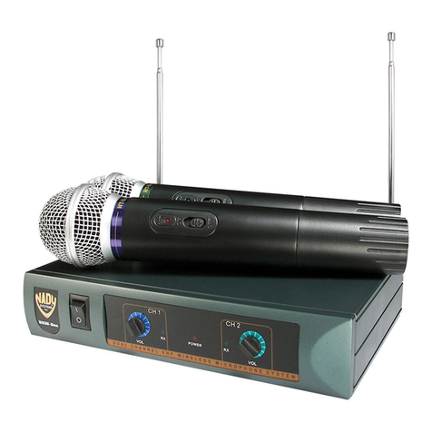
The battery powered controller with three (optionally
four) transmission channels is located in a fracture and
impact resistant industrial housing. Each channel
corresponds to a switching application via pushbutton
or switch. The battery life is about 4 years. The internal
12 volt battery (Type MN21 23A) can be replaced by
loosening the 4 upper Phillips screws (see
section
5.2).
Functioning: The FT-100 transmitter module sends
serial data to the FR-100 receiver and then evaluates
the feedback from the receiver.
For a detailed component description refer to chapter
5.
1.2.2 Receiver Module FR-100
The FR-100 receiver component with switching
function has a 12 …24 VDC voltage supply input and
is equipped with four potential-free changeover
relay outputs for switching the respective
pushbutton or switch.
Functioning: The radio receiver FR-100 evaluates the
radio signals of the FT-100 transmitter module and
switches one or more of the four potential-free
changeover relays ON and / or OFF. The switching
mode "Key" or "Toggle" can be set individually for
each individual relay contact.
For a detailed component description refer to chapter
6.
Figure 1: Transmitter Module FT-100
Figure 2: Receiver Module FR-100

FS-100_BA_EN_2018-01-14.docx / Rev: 0
4
2Indented Use
The FT-100 transmitter module sends serial data to the FR-100 receiver and then evaluates the
feedback from the receiver. It is forbidden to modify or change component parts of the product.
The electronics are protected against specified external influences according to the technical data
and may only be used within environments in accordance with this information.
Used connecting cables must not be longer than 1 meter.
The system component FR-100 verifies coded radio frequency signals sent by the FS-100 transmitter
module and operates relay outputs on receipt of a correct signal. The rated current for each relay is
10 A / 230 VAC maximum.
The transmitter module FT-100 is only suitable for receivers of the FR-100 series (and vice versa).
3Safety
It should be noted that for applications that could put human life at risk, by using radio
connection there is always present a potential hazard due to extraneous disturbances.
The Operating Instructions need to be followed at all times!
Ensure that the product is isolated from any power supply before opening. Opening
and installation of the product must be performed only by a qualified electrician.
Safety Precauons
Every applicable regulations and standards have to be observed, in particular VDE0100,
VDE0550/0551, VDE0700, VDE0711 and VDE0860. The use of solid cables for connection is
recommended since terminal design does not incorporate stress relief. The product corresponds to
Safety-Class II (without protective earth terminal) according to VDE0700, IEC335EN60335.
For commercial use, compliance must be made with the recommendations and instructions of the
responsible regional/national authorities.
For use in public institutions, schools, clubs and do-it-yourself workshops the operation of this product
has to be supervised by qualified personnel.
We do not assume any warranty and liability for personal or material damages caused by incorrect
application or by failure to follow these operating instructions!
For reasons of safety and conformity (CE) it is not permitted to modify or change parts of the product.
Opening and installation of this product has to be performed only by authorized electricians.
If you have not the corresponding expertise, ask qualified specialists or workshop for installation and
commissioning. This product and connected devices can be damaged as a result from inappropriate
installation, connection or operation.
Furthermore, this could lead to other damages e.g. short circuit, fire or electric shock.
The product must not be installed or used in places where a risk of explosion may exist.
Do not touch antenna connectors with live parts!
The FS-100 system corresponds to the state of the art. Residual hazards may result from the system if
it is assembled or commissioned unqualified.

FS-100_BA_EN_2018-01-14.docx / Rev: 0
5
4Operating Range
The FS-100 radio system is designed for a large operating range of up to 200 meters. Walls including
steel reinforced concrete can be penetrated. The maximum range can be achieved under optimum
conditions and by line-of-sight contact between transmitter and receiver without disruption by
external high frequency disturbances.
The following are possible causes that could reduce range of operation:
Obstructing buildings, vegetation or other factors will substantially reduce the operating
range.
The distance between the antenna and the operator’s body or other conducting objects
(e.g. Earth) may influence the operating range.
Background “electrical noise” could be relatively high so that the signal-to-noise-ratio may
decease and therewith the operating range. Also other devices, with similar operating
frequency, operated in the neighborhood of the receiver may reduce the sensitivity.
Operating the receiver adjacent to badly shielded electronic components (e.g. PCs) that can
produce electromagnetic distortion, may severely reduce the range of operation and could
result in intermittent operation.
Adjustable and open components should not be adjusted or modified!
5Description FT-100 (Handheld Transmitter)
Baery Supply
The handheld transmitter is powered internally by a 12 volt MN21 23A battery. This is already
included in the delivery. The battery life is up to 4 years, depending on the type of loading and
application. If the range is greatly reduced or no function tripping is possible, the battery must be
replaced. A battery monitoring LED is only equipped when ordering a FS-100 system with option „L“
(see 8). The procedure for changing the battery is described below.
Baery Change
Procedure for changing the battery:
1. Loosen the 4 upper Phillips screws
2. Turn the device over and remove the bottom cover
3. Remove the battery and insert a new one
Please pay attention to the correct polarity
and only use batteries of the type MN21 23A
(recommended: Duracell 12 V MN21 Alkaline).
Disposal of Batteries:
Outside Germany please contact your local authorities for disposal or recycling information.
Figure 3: Battery Change

FS-100_BA_EN_2018-01-14.docx / Rev: 0
6
LED Funcons and Acousc Beeper (Opon „L“)
The functions described in this section are only available if option "L" has been ordered!
The FT-100 hand-held transmitter allows remote control of three (optional up to four) functions of a
FR-100 receiver. The user gets information about the radio system and the communication by the
following visual and auditory signals:
LED 1 (green) flashes 3 times per second while pressing a button:
Proper reception is acknowledged
LED 1 (green) double-flashes 3 times per second while pressing a button:
Proper reception is acknowledged and transmitter battery is low
LED 1 (green) flashes often within 2 seconds: The receiver does not answer
LED 2 (red) blinks 3 times: Weak receiver supply
LED 2 (red) blinks 8 times: Critical receiver supply
LED 3 (red) lights when a button is pressed: key lock is active (option)
1 x Beep: switch on acknowledgement received
1 x Beep: switch off acknowledgement received
3 x Beep after 2 seconds: No switch on acknowledgement received
3 x Beep after another 2 seconds: No switch off acknowledgement received
FR-100 receivers acknowledge a proper reception by using the weak receiver supply signal.
Each transmitter has an individual serial number. If more transmitters for one receiver are used, than each
transmitter must be programmed to the receiver.
With a FR-100 receiver it is possible to learn transmitters with or without acknowledgement. The
corresponding learning process may result in a reconfiguration of the transmitter. This may lead to
incompatibility with receivers, which have previously learned this transmitter.
Figure 4: LED and Beeper Signals

FS-100_BA_EN_2018-01-14.docx / Rev: 0
7
Keylock Funcon (Opon „T“)
Important note: The interlock function (Option „T“) is supplied on request only, as this feature is
unsuitable for most industrial applications. In addition, it can only be implemented for the FS-101
version with four channels (switches / buttons) and together with the "L" option, since all four
switches / buttons and the LED functions are required for this.
You can find information about the order options in the section Type Designation / Order Code 8.
5.4.1 Activate Keylock Function
Press and hold push button 3 und 4 for at least 2 seconds until LED 3 indicates the activation. Please
take in account that during this time the radio function 3 and 4 is transmitted. After activation no
radio signal is transmitted anymore. At any time you press one of the push buttons LED 3 will
indicate the activated keylock function.
5.4.2 Deactivate Keylock Function
Press first push button 1 followed within 1.5 seconds by push button 4. Please take in account that in
this case the radio function 4 is transmitted.
Frequency Change (f1 / f2)
The module can be operated with two different operating frequencies:
f1 = 433.62 MHz (standard setting)
f2 = 434.22 MHz (optional setting)
In rare cases it is necessary to change the frequency because of interference from other devices.
In this case, the unit can be factory set to the second operating frequency. For this you have to send
the transmitter module back to the manufacturer.
The associated receiver must then also be switched to the second frequency. The procedure for this
is described in section 6.3.

FS-100_BA_EN_2018-01-14.docx / Rev: 0
8
6Description FR-100 (Receiver)
Power Supply Voltage
The receiver module type FR-100 needs a power supply of 12 …24 VDC. The used supply has to
deliver about 200 mA with active relays. The corresponding terminals are marked on the internal
board as + (12 ... 24 VDC) and (0 V / GND). The board is accessible by removing the housing cover.
Relay Switching Funcons
Each switch or button of the transmitter FT-
100 is permanently assigned to a relay contact
of the receiver module FR-100 and activates
the respective contact when actuated.
You may select between Key- or Toggle-
function separately for each relay by putting
Jumper X1 to X4 in position 1:1 (key function)
or in position ON/OFF (toggle function).
If the key function (1:1) is selected the relays
will stay activated as long as the transmitter
key remains active, while the toggle function
permits to switch on and off the relay with the
same transmitter key (each signal command
puts the relay into the opposite state).
The relays are connected via the respective
screw terminals which are indicated on the
board.
Frequency Change (f1 / f2)
The module can be operated with two different operating frequencies:
f1 = 433.62 MHz (standard setting)
f2 = 434.22 MHz (optional setting)
By default, jumper X5 is in position f1. To select the working frequency f2, set the jumper to position
f2 and restart the receiver. Please note that the corresponding transmitter also has to be switched to
f2 (refer to section 5.5).
7Installing the FT-100 / FR-100 System
For the location of the FR-100 receiver module, select a place which is not shielded by conducting
objects and position the antenna in such a way that it is not subject to interference from the rest of
the circuit and is parallel to the transmitter antenna.
Connect the supply voltage to the input 12 … 24 VDC and the POWER LED will turn on.
Take care of the technical data and of the supply polarity (8). Maximum supply
voltage is 24V DC. Higher supply voltages will destroy the receiver. In continuous
operation of all 4 relays the supply voltage must not exceed 12 V.
Figure 5: FR-100 Jumper Settings

FS-100_BA_EN_2018-01-14.docx / Rev: 0
9
Programming the FT-100 Switches/Buons
In order to learn a transmitter or a key it is necessary to switch from the normal receive mode to a
learn mode by specific pressing of the LEARN/ERASE button (see Figure 5). After that a switch or
button of the FT-100 transmitter has to be pressed in a distance of no less than 1m.
Following learn modes are available:
7.1.1 Learn Mode I:
Learn a transmitter with acknowledgement of the transmitter signal. Press the LEARN/ERASE button
1 x shortly. The light of the LED beside the button interrupts 1 x every 2 seconds.
7.1.2 Learn Mode II:
Learn a single key with acknowledgement of the key signal. Press the LEARN/ERASE button
2 x shortly. The light of the LED beside the button interrupts 2 x every 2 seconds.
7.1.3 Learn Mode III:
Learn a transmitter without acknowledgement of the transmitter signal. Press the LEARN/ERASE
button 3 x shortly. The light of the LED beside the button interrupts 3 x every 2 seconds. The
corresponding transmitter is configured automatically.
7.1.4 Learn Mode VI:
Learn a single key without acknowledgement of the key signal. Press the LEARN/ERASE button 4 x
shortly. The light of the LED beside the button interrupts 4 x every 2 seconds. The corresponding
transmitter is configured automatically.
Each learn mode returns to normal receiving mode if a valid signal has been received, or if the
LEARN/ERASE button is pressed again, or if the learn- and erase mode is already active more than 30
seconds.
The receiver module may learn up to 60 different transmitter codes. A successful learn process will
be signalized by a flash of the LED besides the LEARN/ERASE button. Possible causes for failed learn
processes are a full list of learned transmitters or the list contains already the transmitter.
Check for error free operation of the receiver by pressing the transmitter buttons desired. The state
of each relay is indicated by appropriated control LEDs.
Delete FT-100 Transmiers or Keys
In order to erase a transmitter or a key it is necessary to switch from the normal receive mode to an
erase mode by specific pressing of the LEARN/ERASE button. Keep the LEARN/ERASE button pressed
down for at least 3 seconds. The LED beside the button begins to flash. Pressing afterwards a FT-100
transmitter key in a distance of no less than 1 meter causes the erasure of all list entries
corresponding to this transmitter. Instead of pressing a transmitter button you can press the
LEARN/ERASE button for at least 3 seconds again to clear the whole list of learned transmitters.
If you are sure that all functions are properly working you may start wiring of the relay contacts. If
the relay voltage exceeds 40 V, ensure that the receiver is free of voltage before perform starting
wiring.

FS-100_BA_EN_2018-01-14.docx / Rev: 0
10
8Type Designation / Order Code
FS - 1XX - L - T - H
System Information
FS
Bidirectional Radio System / Remote Controller
Transmitter / Receiver
100
FT-100 (3-channel transmitter) + FR-100 (receiver)
101
FT-100 (4-channel transmitter) + FR-100 (receiver)
Options
L
Transmitter module FT-100 with
battery monitoring
acoustic signals (beeper)
status LEDs
T*
Transmitter module FT-100 with mechanical
interlock for buttons resp. switches*
H
Receiver module FR-100 with snap-on housing
for 35 mm top hat rail
*) Available only on request
Order / reorder of single components
Please note: Transmitters and receivers as well as desired options, can be ordered separately. In
this case, the order code shown above is also applicable, but then FT or FRmust be indicated as
system information (instead of FS).
Examples of orderable individual components:
FT-100 3-channel transmitter module (standard version)
FT-100-L 3-channel transmitter module with battery monitoring, beeper and status LEDs
FT-101-L 4-channel transmitter module with battery monitoring, beeper and status LEDs
FR-100 Receiver module with switching function (standard version)
FR-100-H Receiver module with switching function and top hat rail housing

FS-100_BA_EN_2018-01-14.docx / Rev: 0
11
9Technical Specifications
Transmier Module FT-100
Power supply:
12 V battery, type MN21 23A
(recommended: Duracell 12 V MN21 Alkaline)
Current consumption:
Normal operation: approx. 6 mA (on average)
At standby: 0.1 μA
Battery service life:
Up to 4 years (depending on type of loading / application)
Operation frequency:
f1 433.62 MHz; f2 434.22 MHz (see
5.5)
Channels for switching functions:
3, optionally 4 (see
8)
Antenna:
50 Ω (integrated)
Option al indicators:
Battery LED, status LEDs and Beeper (option “L”,
8)
Temperature range:
-20° C …+ 65° C
Housing:
Plastic, break and impact resistant
Housing dimensions (L x W x H):
140 x 62 x 46 mm / 5.51 x 2.44 x 1.81” (without keys)
140 x 62 x 70 mm / 5.51 x 2.44 x 2.76” (with keys)
Protection class:
IP67
Receiver Module FR-100
Power supply:
12.0 ... 24.0 VDC (maximum 26 V)
Current consumption:
At standby: 25 mA
All relays energized : ca. 200mA
Operation frequency:
f1 433.62 MHz; f2 434.22 MHz (see
5.5)
Antenna:
50 Ω (integrated)
Relay outputs:
4 potential free changeovers
Relay switching power:
230 VAC / 10 A; 30 VDC / 5 A
Temperature range:
-20° C …+ 65° C
Connections:
Internal screw terminals
Housing:
Standard: surface-mounted housing, plastic
Option „H“: snap-on housing for top hat rail (
8)
Housing dimensions (L x W x H):
130 mm x 85 mm x 37 mm / 5.43 x 3.35 x 1.46”
Protection class:
IP54
Conformity
According to the 2014/53/EU (RED) standard
Health and safety:
EN 60 950-1:2006 + A11:2009 + A1:2010 + A12:2011 +
AC:2011 + A2:2013
Electromagnetic compatibility:
EN 301 489-1 : V1.9.2 / EN 301 489-3 : V1.6.1
Use of the radio frequency spectrum:
EN 300 220-2 : V2.4.1
Assessment of hazardous substances:
EN 50581:2012
Declaration of conformity
see next page

FS-100_BA_EN_2018-01-14.docx / Rev: 0
12
Konformitätserklärung gemäß der Richtlinie 2014/53/EU (RED)
Declaration of Conformity in accordance with the Directive 2014/53/EU (RED)
Die alleinige Verantwortung für die Ausstellung dieser
Konformitätserklärung trägt der Hersteller / This
declaration of conformity is issued under the sole
responsibility of the manufacturer:
Beck Kommunikationselektronik
Bodenseeallee 18
DE 78333 Stockach
erklärt, dass die Funkanlage / declares that the Radio equipment:
SHR-12 L4
HSV 13.20
FS-100
Fernwirkempfänger / remote control receiver
mit den Bestimmungen der nachfolgenden EU-Richtlinie übereinstimmt /
complies with the requirements of the following directive:
2014/53/EU European Radio Equipment Directive (RED)
2011/65/EU Restriction of Hazardous Substances (RoHS)
und dass die nachstehenden, harmonisierten europäischen Normen zur Anwendung gelangt sind /
and that the following harmonized european standards has been applied:
Gesundheit und Sicherheit / Health and safety:
EN 60 950-1:2006 + A11:2009 + A1:2010 + A12:2011 +
AC:2011 + A2:2013
Elektromagnetische Verträglichkeit / Electromagnetic compatibility:
EN 301 489-1 : V1.9.2
EN 301 489-3 : V1.6.1
Nutzung des Frequenzsprektums / Use of the radio frequency spectrum:
EN 300 220-2 : V2.4.1
Beurteilung gefährlicher Stoffe / Assessment of hazardous substances:
EN 50581:2012
Ort, Datum / Place, date of issue:
Verantwortliche Person / responsible person:
Name und Unterschrift / name and signature:
Stockach, 10.01.2018
Alexander Beck, Geschäftsführer
Table of contents
