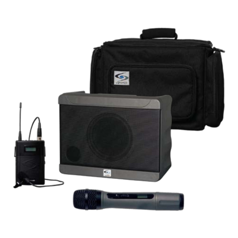
Lightspeed Delta X6 User manual

User Notes
System Overview ............................................................................................. 1
System Controls and Functions:
Delta X6
Charging the Battery ............................................................................... 2
Audio Controls ........................................................................................ 3
Back Panel .............................................................................................. 4
Wireless Receivers ................................................................................. 5
Handheld Microphone Transmitter .............................................................. 6
Belt-pack Transmitter .................................................................................. 7
Operating Instructions:
Audio Inputs ................................................................................................ 8
Audio Outputs ............................................................................................. 9
Wireless Receivers ................................................................................... 10
Handheld Microphone Transmitter ............................................................ 11
Belt-pack Transmitter ............................................................................. 15
Belt-pack Microphones ....................................................................... 15
Wireless Microphone Operation ............................................................ 19
Trouble Shooting Guide ............................................................................... 20
System Specifications ................................................................................ 21
Channel/Frequency Assignments ............................................................. 22
Components & Accessories ....................................................................... 23
Warranty Information .................................................................................. 24
Equipment Log ............................................................................................. 25
User Notes ................................................................................................... 26
LightSPEED is a trademark of LightSPEED Technologies, Inc. Other names and brands may be claimed as the property of others.
Copyright © 2005 LightSPEED Technologies, Inc., All rights reserved. Printed in USA.
Table of Contents
LightSPEED
Delta X6
27

System Overview
The DELTA X6 Wireless Sound System is an easy-to-use, highly portable amplification
system designed for both indoor and outdoor use. The system contains inputs for up to
two UHF wireless microphone receivers, one input for a wired microphone and one input
for a line level audio source coming from a CD/DVD player, TV/VCR, Computer, etc.
There is an adjustable-level output to connect into an external source such as an
assistive listening system or a voice recorder. Users can also connect to a passive
speaker, in order to cover a larger area. The system operates on rechargeable battery
power for up to 6 hours, and can also be plugged into AC power if longer run-time is
desired. The entire system and accessories fit nicely in the rugged carrying case,
which makes it highly portable and lightweight.
The wireless receivers contain 100 user-selectable frequencies ranging from 620 MHz
to 745MHz. Each receiver contains a clear-channel scanner (a touch of a button
automatically selects a clear frequency), low battery indicator (for the transmitter), and
adjustable squelch control. The system is available with a variety of handheld, lapel,
and headset microphones.
ON
LightSPEED
IMPORTANT NOTE:
To take full advantage of the features the
DELTA X6 has to offer, as well as its applications, please take time to
read through the entire manual.
Your DELTA X6 documentation package consists of a User’s Manual and a Quick Start
Guide. The User’s Manual has two comprehensive sections,
Controls and Functions
and
Operating Instructions.
For an experienced user, follow the steps on the Quick Start
Guide to get your Delta X6 up and running in a matter of minutes.
26
1
User Notes

LightSPEED
7100R
UHF
DIVERSITY
RECEIVER
AB
LOW
BAT SCAN SQ
RF
CHANNEL
BASS
TREBLE
AUX IN/
MIC IN
WM 2
WM 1
WM 2
LightSPEED
7100R
UHF
DIVERSITY
RECEIVER
AB
LOW
BAT SCAN SQ
RF
CHANNEL
WM 1
POWER
ON
GREEN:
FULL
BATT
RED:
LOW
BATT
WM 1 Knob
Battery Status LEDs
• Red = Low Battery
• Green = Power ON
Power for the System
• After the system is fully charged, turn the
WM1 Knob clockwise to turn the system on.
• The green LED will light.
Connect
to Delta X6
Connect
to 110V AC
Connect
AC Cord
to Charger
DELTA X6 CHARGER
LED
Controls and Functions
Power/Charging
Back Panel
Using the Battery Charger
After unpacking the unit for
the first time, please charge
the batteries for at least
10 hours before operation.
Determining Battery Status
There are two LEDs on top of the Delta X6 that indicate battery status. The GREEN LED
will light whenever the power is switched on, unless the battery is dead. As the battery
discharges, the RED LED will begin to glow, and the
GREEN LED will stay lit. When the RED LED is
glowing brightly, the battery is very low. Once the
battery discharges to an unusable level, the system
will shut off and you will need to connect the
battery charger.
While the system is charging it may be left on and
operated as normal. It is designed in such a way
that it can provide power for the system while the
batteries are charging. However,
to fully charge the system, it
should be switched OFF until the
LED shows GREEN on the battery
charger.
•
RED means fast-charge mode.
The battery is very low or completely
discharged.
• ORANGE means trickle-charge mode.
The battery is not yet fully charged.
• GREEN means no charging.
The battery is fully charged.
System Top View
To charge the system battery, plug the charger/power supply cable into the Delta X6
and plug the other end into an AC outlet. The LED on the battery charger will light
up. The color of the LED indicates the charging status as follows:
2
Equipment Log
ON
LightSPEED
Record your system serial numbers and purchase information.
This is helpful when ordering additional components, accessories,
and/or warranty service.
Component
Receiver[s]
Transmitter[s]
Microphone[s]
Serial Number
Purchase Information
Your Name/Company
Purchase Date
Dealer Name/Location
Invoice #
Delta X6
Power Supply
25

LightSPEED
7100R
UHF
DIVERSITY
RECEIVER
AB
LOW
BAT SCAN SQ
RF
CHANNEL
BASS
TREBLE
AUX IN/
MIC IN
WM 2
WM 1
BASS
TREBLE
AUX IN/ MIC IN
WM 2
WM 1(Power)
WM 2
LightSPEED
7100R
UHF
DIVERSITY
RECEIVER
AB
LOW
BAT SCAN SQ
RF
CHANNEL
WM 1
POWER
ON
GREEN:
FULL
BATT
RED:
LOW
BATT
3
4
2
5
1
System Top View
Controls and Functions
LightSPEED
7100R
UHF
DIVERSITY
RECEIVER
AB
LOW
BAT SCAN SQ
RF
VOL
MaxPWR/Min
CHANNEL
BASS
TREBLE
AUXIN/
MICIN
WM2
WM1
WM2
LightSPEED
7100R
UHF
DIVERSITY
RECEIVER
AB
LOW
BAT SCAN SQ
RF
VOL
MaxPWR/Min
CHANNEL
WM1
POWER
ON
GREEN:
FULL
BATT
RED:
LOW
BATT
24
3
Audio
Control Panel
1.1.
1.1.
1. WM1/Power:WM1/Power:
WM1/Power:WM1/Power:
WM1/Power: Turn this knob clockwise to power up the system. Rotate to adjust
the volume of Wireless Microphone 1 (WM1).
2.2.
2.2.
2. WM2:WM2:
WM2:WM2:
WM2: Controls the volume of Wireless Microphone 2 (WM2) if a second wireless
receiver is installed.
3.3.
3.3.
3. AUX IN/MIC IN:AUX IN/MIC IN:
AUX IN/MIC IN:AUX IN/MIC IN:
AUX IN/MIC IN: Controls the volume of a wired microphone plugged into MIC IN
on the back of the system and the volume of an auxiliary piece of equipment
plugged into the AUX IN on the back of the system.
4.4.
4.4.
4. TT
TT
Treble:reble:
reble:reble:
reble: Controls the level of high frequency sound output for the system.
5.5.
5.5.
5. Bass:Bass:
Bass:Bass:
Bass: Controls the level of low frequency sound output for the system.
DELDEL
DELDEL
DELTT
TT
TA X6 WA X6 W
A X6 WA X6 W
A X6 Warranty Statementarranty Statement
arranty Statementarranty Statement
arranty Statement
The LightSPEED Technologies DELTA X6 is warranted to be free from defects in
materials and workmanship for the period of SIX (6) YEARS from the date of original
purchase, subject to the following conditions:
1. The product must have been purchased from LightSPEED, an authorized
LightSPEED Technologies Dealer, or LightSPEED representative.
2. LightSPEED Technologies must perform all warranty service. Any service per-
formed without the authorization of LightSPEED Technologies will void the entire
warranty.
3. This warranty does not cover any product that has been subjected to negligent
use, connection to improper power source, misuse, or operated beyond its manufac-
tured specifications and limits, or has not been reasonably maintained.
4. Lead-Acid Batteries installed in the DELTA X Wireless Sound Systems shall be
warranted for a TWO (2) YEAR period from date of purchase.
5. Rechargeable AA Nickel Metal Hydride (NiMH) batteries sold with some sys-
tems shall be warranted for ONE (1) YEAR from date of purchase.
6. Warranty shall not apply to batteries (other than those mentioned in items 4 and
5 above), exterior finish, AC power cords, bulbs, or any other failings due to normal
wear.
7. Warranty is void when equipment is subjected to adverse temperature, humid-
ity, moisture, or other conditions that are not considered normal environmental
conditions.
8. LightSPEED lapel, lavaliere, and headset microphones shall be warranted for
ONE (1) YEAR from date of purchase.
9. Third party microphones and accessories shall be under the original
manufacturer's warranty.
10. Warranty for wireless receivers and transmitters shall be THREE (3) YEARS from
date of purchase.
11. This warranty excludes all damages and defects caused by shipping, transport-
ing, or inadequate packaging for shipment.
12. Customers are responsible for freight charges to LightSPEED Technologies for
service. LightSPEED Technologies will pay for return freight to the end user by most
reasonable method.
For warranty service, please contact LightSPEED Technologies customer service
department at (800) 732-8999 to obtain Return Authorization
approval and RA number.
TIP: The bass and treble controls can be used to reduce feedback
(“squealing” or “howling”). If you hear high-pitched “squealing”, lower the
treble setting. If you hear low-pitched “howling”, lower the bass setting.
Warranty

4
1.1.
1.1.
1. MIC IN:MIC IN:
MIC IN:MIC IN:
MIC IN: This 1/4” jack provides an input for a wired handheld microphone.
2.2.
2.2.
2. AUX IN:AUX IN:
AUX IN:AUX IN:
AUX IN: This 3.5 mm jack provides an input for audio from an external device such
as a CD player, TV/VCR, computer, etc.
3.3.
3.3.
3. AUX OUTAUX OUT
AUX OUTAUX OUT
AUX OUT::
::
: This 3.5mm jack provides an adjustable-level audio output that can be
connected to a recorder or assistive listening device.
4.4.
4.4.
4. AUX OUT VOLUME:AUX OUT VOLUME:
AUX OUT VOLUME:AUX OUT VOLUME:
AUX OUT VOLUME: This knob controls the level of the 3.5mm AUX OUT Jack.
Counterclockwise represents a microphone level signal, while fully clockwise
represents a line level signal.
5.5.
5.5.
5. AUX OUTAUX OUT
AUX OUTAUX OUT
AUX OUT::
::
: This 1/4” jack provides a line level output signal that can be
connected to a recorder, assistive listening device, etc.
6.6.
6.6.
6. SPEAKER OUT (SWITCHED):SPEAKER OUT (SWITCHED):
SPEAKER OUT (SWITCHED):SPEAKER OUT (SWITCHED):
SPEAKER OUT (SWITCHED): This 1/4” jack can be used to connect to an
external passive speaker.
Connection into this jack will mute the internal speaker
of the DELTA X6.
7.7.
7.7.
7. FUSE:FUSE:
FUSE:FUSE:
FUSE: The fuse holder is accessible using a flat-blade screwdriver. Push in and
rotate 1/4-turn counterclockwise to remove.
See specifications for replacement
fuse type.
8.8.
8.8.
8. DC CHARGE INPUTDC CHARGE INPUT
DC CHARGE INPUTDC CHARGE INPUT
DC CHARGE INPUT::
::
: This jack provides a connection for the Delta X6 battery
charger/AC power cord.
Controls and Functions
Back Panel
SPEAKER OUT
(SWITCHED)
FUSE
4A 250V
DC CHARG INPUT
MODEL NUMBER
BC-DELTA-12V
ONLY
MIC IN
AUX IN
AUX OUT
AUX OUT
AUX OUT
VOLUME
SPEAKER OU
T
(SWITCHED)
FUSE
4A 250V
DC CHARGE
INPUT
8
7
6
AUX OUT
AUX OUT
VOLUME
AUX OUT
AUX IN
MIC IN
3
4
2
5
1
Battery
Compartment
23
Components & Accessories
AMP-DELTA-X6 DELTA X6 Amplifier with 6" Speaker
RX-7100R 100 Channel UHF Receiver Module
TX-HM900 100 Channel UHF Handheld Transmitter
TX-BP900 100 Channel UHF Belt-pack Transmitter
BA-LA12-5 12V 4.6 AH Lead Acid Battery
BC-DELTA-12V Battery Charger for DELTA X6
AC-SPDELTA-X6 Carry Bag for DELTA X6
MC-LS4S Semi-directional Microphone with TA4F Connector and Lapel
Clip
MC-TK250S Noise-Canceling Headset Microphone with TA4F Connector
BC-TX900 Battery Charger for BP900 or HM900
(Optional)
BA-NH1 AA NiMH Rechargeable Battery
(Optional)
Contact your LightSPEED representative for details, pricing and availability.
Delta X6 Individual Components and Accessories
Order Code Product Description

LightSPEED
7100R
UHF TRUE
DIVERSITY
RECEIVER
AB
LOW
BAT SCAN SQ
RF
CHANNEL
7
100-channel UHF Receiver Module
3
4
2
56
1
System Specifications
ON
LightSPEED
22
5
Controls and Functions
LightSPEED
7100R
UHF
DIVERSITY
RECEIVER
AB
LOW
BAT SCAN SQ
RF
VOL
MaxPWR/Min
CHANNEL
BASS
TREBLE
AUXIN/
MICIN
WM2
WM1
WM2
LightSPEED
7100R
UHF
DIVERSITY
RECEIVER
AB
LOW
BAT SCAN SQ
RF
VOL
MaxPWR/Min
CHANNEL
WM1
POWER
ON
GREEN:
FULL
BATT
RED:
LOW
BATT
1.1.
1.1.
1. Channel Control (00-99):Channel Control (00-99):
Channel Control (00-99):Channel Control (00-99):
Channel Control (00-99):
The left button controls the
number on the left (0-9). Each
touch of the button moves the
number up one until it gets to
nine, and then it cycles back to
zero. The right button has the
same function for the number
on the right.
Wireless Receivers
Control Panel
2.2.
2.2.
2. TT
TT
Transmitter Low Batterransmitter Low Batter
ransmitter Low Batterransmitter Low Batter
ransmitter Low Battery Indicator:y Indicator:
y Indicator:y Indicator:
y Indicator: This LED will light to indicate a low battery in
the transmitter (belt-pack or handheld) set to the same channel.
3.3.
3.3.
3. RF Channel “A” Indicator:RF Channel “A” Indicator:
RF Channel “A” Indicator:RF Channel “A” Indicator:
RF Channel “A” Indicator: The “A” LED lights up indicating the “A” channel tuner
is receiving the strongest RF signal.
4.4.
4.4.
4. RF Channel “B” Indicator:RF Channel “B” Indicator:
RF Channel “B” Indicator:RF Channel “B” Indicator:
RF Channel “B” Indicator: The “B” LED lights up indicating the “B” channel tuner
is receiving the strongest RF signal.
5.5.
5.5.
5. Scan:Scan:
Scan:Scan:
Scan: Press this button to automatically select a channel that is free from
interference.
6.6.
6.6.
6. Squelch Adjustment:Squelch Adjustment:
Squelch Adjustment:Squelch Adjustment:
Squelch Adjustment: Adjusts the squelch level for elimination of RF interference.
7.7.
7.7.
7. Receiver Power/Volume Adjustment:Receiver Power/Volume Adjustment:
Receiver Power/Volume Adjustment:Receiver Power/Volume Adjustment:
Receiver Power/Volume Adjustment: The receiver volume adjustment is covered
with a plastic cap. The volume is adjusted at the factory to provide the best signal
level and minimum noise.
There is no need to adjust the receiver volume in the
field.
Installing or Replacing a Receiver Module:Installing or Replacing a Receiver Module:
Installing or Replacing a Receiver Module:
Note: Make sure the Delta X6 is turned off.
Remove the two screws securing the module
or filler panel using a small phillips screwdriver.
To remove the module, use a small flat-blade
screwdriver. Carefully insert the blade under the
face plate edge and nudge it outward. Grasp the
edges with both hands and slide outward. Install
the new module by aligning it with the guide rails
and sliding all the way in to engage the connector
at the rear of the module.
Replace the two screws.
Remove
Screw
Remove
Screw
LightSPEED
7100R
UHF TRUE
DIVERSITY
RECEIVER
AB
LOW
BAT SCAN SQ
RF
CHANNEL
RF Power Output .................................................................................................. 50 mW Maximum
Spurious Emission .................................................................................... >60 dB below the carrier
Macro Frequency Range ................................................. 620 MHz to 745 MHz
[5 Macro-Groups]
Selectable Frequencies .............................................................................................................. 100
Tone-code Frequency .................................................................................................... 32.768 KHz
Pre-emphasis ....................................................................................................................... 50 µsec
Limiter Range ........................................................................................ >30dB of audio overload
Battery Type ............................................................................................................................ 2 AA
Battery Life
[Alkaline] .........................................................................................
Approx. 8 Hours
BP Microphone Connector .................................................................................................... TA4F
BP Weight w/o Batteries ............................................................................................... 3 oz / 85g
HM Weight w/o Batteries ....................................................................................... 4.2 oz / 120g
BP-900 and HM-900 Transmitters
Channel/Frequency Assignments
E ...................................................... 620.000 – 644.750
H ..................................................... 645.000 – 669.750
L ...................................................... 670.000 – 694.750
P ...................................................... 695.000 – 719.750
U ..................................................... 720.000 – 744.750
LightSPEED Frequency
Channel Range
Delta X6 Channel Assignments
Note: Specifications are subject to change without notice.

6
21
Controls and Functions
ON
Wireless Transmitter
Handheld Microphone
1.1.
1.1.
1. Power Switch:Power Switch:
Power Switch:Power Switch:
Power Switch:
Turns the transmitter ON.
2.2.
2.2.
2. LCD Display:LCD Display:
LCD Display:LCD Display:
LCD Display:
Information screen appears when the power is switched on.
3.3.
3.3.
3. Red LED:Red LED:
Red LED:Red LED:
Red LED:
Lights up briefly when power is switched on.
4.4.
4.4.
4. Lock Button:Lock Button:
Lock Button:Lock Button:
Lock Button:
Locks all microphone controls.
5.5.
5.5.
5. Set Button:Set Button:
Set Button:Set Button:
Set Button:
This button is used to enter and save changes to the
transmitter settings.
6.6.
6.6.
6. Up and Down Buttons:Up and Down Buttons:
Up and Down Buttons:Up and Down Buttons:
Up and Down Buttons:
These buttons scroll up and down between setup
screens on the LCD display. They are also used to enter changes in each
setup screen.
7.7.
7.7.
7. Battery Charge Jack:Battery Charge Jack:
Battery Charge Jack:Battery Charge Jack:
Battery Charge Jack:
Optional battery charger plugs in here
(for NiMH batteries only).
8.8.
8.8.
8. Battery Compartment:Battery Compartment:
Battery Compartment:Battery Compartment:
Battery Compartment:
Bottom section of microphone barrel unscrews to
reveal battery compartment.
ON
LOCK SET
HM-900
SET
5
7
UP
6
1
2
DOWN
6
LOCK
4
LCD Display
8
Battery
Compartment
End View of Microphone
CH: 002
3
System Specifications
Nominal SPL [1W/1M] ............................................................................................ 89 dB
Maximum SPL ...................................................................................................... 102 dB
System Power [RMS] .................................................................................. 30 W at 2 W
Music Power ................................................................................................. 40 W at 2 W
Amplifier Type ....................................................................................... Analog Class AB
Frequency Response of amplifier ............................................................... 90 Hz-18 kHz
Speaker System: ............................................................................ Full-Range 6.5" / 4 W
Internal Battery ........................................................................................ 1 x 12V 4.5 AH
Operating Time ............................................................................................... 5-10 Hours
Battery Charger ............................................... External 3-step Automatic Charger/PWM
AC Power ........................................................................................... 100 VAC-240 VAC
Microphone Input ........................................................................................ 1/4-Inch Jack
Wireless Microphones ................................... Up to two 100-Channel UHF True Diversity
Line Input .............................................................................................................. 3.5 mm
Line Output ...................................................................................... 3.5 mm and 1/4-Inch
Tone Controls ......................................................................................... Bass and Treble
Speaker Outputs .................................................................................... 1 Switched 2 W
Dimensions [H x W x D inches] .......................................................... 9.75 x 12.5 x 6.25
Weight [with battery] ................................................................................ 12 lbs. / 5.4 kg
Overall Specifications
7100R Receiver Specifications
Carrier System ............................................................ Microprocessor Controlled PLL Synthesized
Macro Frequency Range ............................................................. 620 to 745 MHz [5 Macro-Groups]
Micro Frequency Range ......................................................................... 25 MHz each Macro Group
Selectable Frequencies ................................................................................................................. 100
Deviation ................................................................................................................ ± 40 KHz Nominal
Sensitivity ......................................................................................... -100 dBm at S/N ratio of >80dB
Tone-code Frequency ................................................................................................... 32.768 KHz
Image Rejection .................................................................................................................... >85 dB
S/N Ration [Max] ................................................................................................................ >105 dB
Note: Specifications are subject to change without notice.

720
Controls and Functions
LightSPEED
DOWN
UP
Set
LightSPEED
On/Off
Switch
Mute
Switch
Red LED
Door
Latch
LCD
Display
10
2
9
1
Battery
Charge
Jack
6
11
9
3
4
Mic
Jack 5
12
GTMT
Gain
Adjust
8
Battery
Com
p
artment
CH: 001
7
Belt
Clip
1.1.
1.1.
1. Power Button:Power Button:
Power Button:Power Button:
Power Button:
Turns the transmitter ON.
(Hold for two seconds.)
2.2.
2.2.
2. LCD Display:LCD Display:
LCD Display:LCD Display:
LCD Display:
Information screen appears when the power is switched on.
3.3.
3.3.
3. Red LED:Red LED:
Red LED:Red LED:
Red LED:
Lights up briefly when power is switched on, flashes
continuously when audio signal is muted.
4.4.
4.4.
4. Mute Switch:Mute Switch:
Mute Switch:Mute Switch:
Mute Switch:
Turns the audio signal on or off.
The red LED will flash when
MUTE is engaged.
5.5.
5.5.
5. Microphone Jack:Microphone Jack:
Microphone Jack:Microphone Jack:
Microphone Jack:
Microphone connects to transmitter here.
6.6.
6.6.
6. Battery Charge Jack:Battery Charge Jack:
Battery Charge Jack:Battery Charge Jack:
Battery Charge Jack:
Optional battery charger plugs in here
(for NiMH
batteries only).
7.7.
7.7.
7. Belt ClipBelt Clip
Belt ClipBelt Clip
Belt Clip
8.8.
8.8.
8. Gain:Gain:
Gain:Gain:
Gain:
Provides adjustment for differing voice levels and microphone
sensitivities.
9.9.
9.9.
9. UP and Down Buttons:UP and Down Buttons:
UP and Down Buttons:UP and Down Buttons:
UP and Down Buttons:
These buttons scroll up and down between setup
screens on the LCD display. They are also used to enter changes in each
setup screen.
10.10.
10.10.
10. Set Button:Set Button:
Set Button:Set Button:
Set Button:
This button is used to enter and save changes to the
transmitter settings.
11.11.
11.11.
11. Door Latch:Door Latch:
Door Latch:Door Latch:
Door Latch:
A door latch button is located on each side. Press both to
open the battery compartment door.
12.12.
12.12.
12. Battery CompartmentBattery Compartment
Battery CompartmentBattery Compartment
Battery Compartment
Wireless Transmitter
Belt-pack
Trouble Shooting Guide
No sound when someone speaks into the wireless microphone:
1.
DELTA X6 power should be turned on.
The
“green battery OK LED”
should be lit. If it
does not light when the system is switched on, the battery is most likely too weak
and needs to be plugged into the charger.
2.
Microphone/transmitter power should be turned on.
If the LCD display does not
show, the batteries are most likely too weak. Plug the microphone/transmitter into
the charger (if the batteries are rechargeable) or replace with alkaline batteries.
The wireless microphone is experiencing drop-out or interference:
1.
The wireless frequency being used may not be a clear channel.
Turn the transmit-
ter off and press the SCAN button on the receiver to find a clear frequency. Then
make sure to select the same channel on the transmitter.
2.
Squelch adjust on the receiver is set too high.
If this squelch is set too high (fully
clockwise), this can drastically reduce the range of the transmitter, resulting in more
frequent dropout.
3.
Squelch adjustment is set too low.
In areas of severe interference (large downtown
urban areas, airports, military bases, etc) it may be necessary to turn the squelch
up slightly to avoid outside interference.
4.
Transmitter is out of range of receiver.
The transmitters do have a maximum range
of about 300-350 feet in an open field environment. This range can be dramatically
reduced indoors and when large objects (such as a wall) may be obstructing the
path directly between transmitter and receiver. If this is the case, it may be
necessary to position the two closer together.
5.
Batteries are very weak.
Right before the batteries are about to die, it can
drastically affect the overall performance of the system. Make sure to check the
battery status of both the transmitter and DELTA X6 amplifier.
WARNING: Do not attempt to charge alkaline batteries. They can overheat
and expand, creating a significant hazard and damaging the transmitter.
(This is not covered by warranty.)
If you have gone through this trouble shooting guide and are still having problems,
write down the serial numbers of your system and call the LightSPEED Service
Department at
1-800-732-8999
7:00 am - 5:00 pm PST
3. The transmitter and receiver should be set to the same channel and the blue RF
LED (A or B) on the receiver should be lit.
4. Make sure the
“mute light”
(on the belt-pack transmitter) is not flashing.
5. Verify the receiver and transmitter are in the same frequency group.
• Turn the Delta X6 off and then on again. The letter code for the frequency group
will blink on the receiver module.
• Open the battery compartment of the transmitter to find the frequency group
sticker.

Operating Instructions
8
2. Rotate the AUX IN/MIC IN control clockwise to increase the volume. When voice
is spoken into the wired microphone, amplified sound should be heard over the
speaker.
SPEAKER OUT
(SWITCHED)
FUSE
4A 250V
DC CHARG INPUT
MODEL NUMBER
BC-DELTA-12V
ONLY
MIC IN
AUX IN
AUX OUT
AUX OUT
AUX OUT
VOLUM E
3.5mm AUX IN
3
1/4" MIC IN
1
Back Panel View
Control Panel Top View
AUX IN/MIC I
N
Control Knob
24
AUX IN/
MIC IN
Both wired and wireless microphones can be used simultaneously as there is a
built-in mixer to mix or balance both signals.
Input from External Audio Equipment
Below are instructions on how to connect an external audio source such as an MP3
Player, CD/DVD, TV/VCR, or computer to the DELTA X6.
3. Connect a cable from an audio source to the 3.5mm jack labeled AUX IN on the
back of the DELTA X6.
NOTE: When hooking up auxiliary equipment, you may
need an adaptor depending on the connections available.
4. With the DELTA X6 turned on, adjust the AUX IN / MIC IN volume knob on the top
of the unit to a desired level.
Audio Inputs
Back Panel
Wired Microphone Operation
1. To use a wired microphone, plug the wired microphone cable connector into the
1/4” input labeled MIC IN on the back panel.
19
Operating Instructions
ON
Wireless Microphone Operation
1
.RF Indicator Lights: When both the system and the transmitter are on and
operating on the same channel you will see an RF Indicator Light (either A or B) on
the receiver.
2. Volume Adjustment: While speaking into the microphone,
slowly turn the WM1 Volume knob (or WM2 depending on which
microphone you are operating) clockwise until you reach the desired level.
NOTE: Do not stand directly in front of the DELTA X speaker with the
microphone on. This will result in feedback or ‘squealing’. It is best to
stand behind or off to the side of the unit when setting volume level.
3. Squelch Adjustment: In areas that may have very high radio frequency traffic, it
may be necessary to adjust the squelch level to block out potential interference.
• Maximum squelch (full clockwise) reduces system reception range, but also
reduces the potential for system interference.
• Minimum squelch (full counterclockwise) increases reception range, but also
increases the potential for system interference.
WM 1
POWER
ON
GREEN:
FULL
BATT
RED:
LOW
BATT
LightSPEED
7100R
UHF TRUE
DIVERSITY
RECEIVER
AB
LOW
BAT SCAN SQ
RF
CHANNEL
100-channel UHF Receiver Module
3
1
WM 1
Knob
2
Squelch
RF LED
Indicators
4
Low
Battery
4. Transmitter Low Battery Indicator: This LED will light to indicate the batteries
in the corresponding transmitter are low and need to be replaced or recharged.
NOTE: In most cases it will not be necessary to adjust the squelch
level. Since the system already has the clear channel scanner, this
will take care of most interference problems.

9
Operating Instructions
Audio Outputs
Back Panel
SPEAKER OUT
(SWITCHED)
FUSE
4A 250V
DC CHARG INPUT
MODEL NUMBER
BC-DELTA-12V
ONLY
MIC IN
AUX IN
AUX OUT
AUX OUT
AUX OUT
VOLUME
SPEAKER OUT
(SWITCHED)
3
1/4" AUX OUT
AUX OUT
VOLUME
3.5mm
AUX OUT
2
1
Battery
Compartment
Output to external
speaker system.
Minimum load
impedance 2Ω.
Audio Output to other Devices
Below are instructions on how to output the mixed audio signal of the DELTA X6 to an
external device such as an Assistive Listening Transmitter or audio recorder. The
DELTA X6 has two Auxiliary Output jacks: An adjustable-level 3.5mm output and a
line-level 1/4” output.
1.1.
1.1.
1. 3.5mm Adjustable-level Auxiliary Output:3.5mm Adjustable-level Auxiliary Output:
3.5mm Adjustable-level Auxiliary Output:3.5mm Adjustable-level Auxiliary Output:
3.5mm Adjustable-level Auxiliary Output: This jack will output audio at
adjustable levels ranging from “Mic-level” to “Line-level”. This should be used
to output to a Personal FM transmitter with the volume set at a lower level
(Mic-level) or a recorder with the volume set at a higher level (Line-level).
2.2.
2.2.
2. 1/4” Line-level Auxiliary Output:1/4” Line-level Auxiliary Output:
1/4” Line-level Auxiliary Output:1/4” Line-level Auxiliary Output:
1/4” Line-level Auxiliary Output: This jack provides a full line-level signal for
a voice recorder or other device. NOTE: A line-level signal is a much stronger
audio signal and should not be input into a personal FM transmitter.
Audio Output to External Speaker
3.3.
3.3.
3. Speaker OUT (switched):Speaker OUT (switched):
Speaker OUT (switched):Speaker OUT (switched):
Speaker OUT (switched): This output jacks allows users to connect the DELTA
X6 to a passive external speaker, typically in a larger area such as a gymnasium
or auditorium. When a speaker is connected to this jack, the main DELTA X6
speaker is muted and all the power is transferred to the external speaker, causing
the DELTA X6 to operate only as a receiver/amplifier.
18
Battery
Compartment
Door
Latch
GT MT
DOWN
Button
UP
Button
Set
Button
NiMH
AKLN
5
6
Operating Instructions
LightSPEED
Charging the Batteries (NiMH Rechargeable Batteries ONLY)
Make sure there are NiMH Rechargeable Batteries in the transmitter before plugging in
the charger.
Wireless Transmitter
Belt-pack
WARNING: Do not attempt to charge alkaline batteries. They can
overheat and expand, creating a significant hazard and damaging
the transmitter.
(This is not covered by warranty.)
6. Replacing the Batteries
• Open the plastic door by
depressing the latches on each
side.
• Insert two AA batteries and snap
the door closed.
Note the polarity
in the battery compartment.
Typical battery life is about 8
hours.
Transmitte
r
Charger
Charger
Connector
Charger Status LED
• RED = charging in progress
• GREEN = batteries fully
charged
LightSPEED
• Switch the transmitter power off.
• Insert the small DC plug into the
jack on the side of the transmitter
labeled “CHG”.
• Plug the other end of the charger
into any standard 110 VAC outlet.
• The Red LED on the charger will
light indicating charge is in process.
• When the batteries are fully
charged, the light on the charger
will turn green.
A full charge can
take up to 8 hours.
5. To Change the Battery Type Setting
• Press the “UP” button twice to get to the battery type screen.
• Press and hold the “SET” button until a blinking cursor appears.
• Use the UP and DOWN buttons to make a selection.
• Press and hold the “SET” button again until the blinking cursor disappears.
Note: The impedance of the external speaker(s) must be 2W or higher.
Most speakers will indicate their impedance on their input panels. You
can connect up to two 4W speakers in parallel, or up to four 8W
speakers in parallel to the “SPEAKER OUT (SWITCHED)” jack.

10
Operating Instructions
LightSPEED
7100R
UHF
DIVERSITY
RECEIVER
AB
LOW
BAT SCAN SQ
RF
CHANNEL
BASS
TREBLE
AUXIN/
MICIN
WM2
WM1
WM2
LightSPEED
7100R
UHF
DIVERSITY
RECEIVER
AB
LOW
BAT SCAN SQ
RF
CHANNEL
WM1
POWER
ON
GREEN:
FULL
BATT
RED:
LOW
BATT
WM 1
POWER
ON
GREEN:
FULL
BATT
RED:
LOW
BATT
LightSPEED
7100R
UHF TRUE
DIVERSITY
RECEIVER
AB
LOW
BAT SCAN SQ
RF
CHANNEL
100-channel UHF Receiver Module
26
4
5
Battery
Low LED
(red)
WM 1
Knob 1
3
Battery
OK LED
(g
reen
)
LED Screen
SCAN
Right
Channel
Left
Channel
Wireless Receivers
17
LightSPEED
GTMT
Alkaline
NiMH
Nickel Metal Hydride
Rechargable
4
CH: 001
3
CH: 001
720.250M
1
2Gain Adjust
GT MT
1. Transmitter Mute:
The MUTE switch turns the transmitter’s audio signal on or off.
The audio is off when the red LED is flashing.
2. Gain Adjust: When changing microphones or users, it may be necessary to adjust
the transmitter gain based on differing microphone sensitivities and voice levels.
• To adjust the microphone gain, turn the MT dial clockwise to increase the gain
and counterclockwise to decrease the gain.
• If you are using a high impedence source, such as a guitar, it will be necessary to
adjust the GT dial. Using a high impedance source requires a special cable.
Contact LightSPEED Technologies for more information.
3. Battery Life Indicator:
The battery life is shown on the primary screen of the LCD.
The 7-step fuel gauge acts as a detailed guide to show the actual life of the battery.
4. Battery Type:
The transmitter will operate with either standard Alkaline Batteries or
Nickel Metal Hydride (NiMH) Rechargable Batteries. Since these types of batteries
have different characteristics, it is important to set the transmitter to the appropriate
type of battery being used so that the battery life indicator will operate properly.
Operating Instructions
LightSPEED
Wireless Transmitter
Belt-pack
WARNING: Do not use NiCad batteries!
They will not charge properly and may
cause damage to the transmitter.
NOTE: Do not mix battery types.
Turn the DELTA X6 On
1. Rotate the WM1 knob
clockwise to turn on.
2. The green LED will light, and the red LED above will glow if the battery is low.
3. When the system is switched on, the receiver will have two letters flashing on the
screen to indicate the corresponding frequency group
(see chart on page 22).
Channel Selection - Receiver
Each receiver has 100 user-selectable channels to choose from. You can either select a
channel manually or by pressing the “SCAN” button, which will automatically select a
clear channel.
4. CLEAR CHANNEL SCAN (Recommended): Make sure the transmitter(s) is
OFF before pressing this button. When this button is pressed, the receiver will
cycle through all 100 channels and select a clear frequency (this process takes
about 20 seconds). Once the receiver selects the clear channel, you will need to
select the same channel on the corresponding transmitter (handheld or belt-pack).
IF YOU HAVE A SECOND RECEIVER (WM2): Verify that WM1 is operating on
a clear channel, and the transmitter for WM1 is turned ON. Make sure the
transmitter for WM2 is turned OFF, and then press the “SCAN” button on the
WM2 receiver. After the WM2 receiver selects a clear channel, set the WM2
transmitter (handheld or belt-pack) to the selected channel.
Manual Channel Selection
5. Pressing the Left Channel button changes the first number (0-9).
6. Pressing the Right Channel button changes the second number (0-9). Once a
frequency is selected, you will need to select the same channel on the
corresponding transmitter (handheld or belt-pack).
NOTE: There are 5 different groupings of 100 channels available, which are sent out to
maximize clear channels in a specific geography. When the system is powered on, the two
letters that initially blink in the Channel window on the receiver indicate the frequency group
(see chart on page 22 for further details).

11 16
Operating Instructions
ON
Channel Selection – Handheld Transmitter
Once a channel has been selected on the receiver, you now need to select that same
channel on the handheld transmitter.
If you have a belt-pack transmitter, go to page 16
for channel selection instructions.
ON
LCD
Display
LOCK SET
HM-900
SET
LOCK
UP
DOWN
Red
LED
ON/OFF
Switch
CH: 002
CH: 002
720.500M
LS
HM-900
SENS SET
LEVEL [2]
NiMH
AKLN
Setup Screens
selectable with
the UP and DOWN
Arrow Buttons
Wireless Transmitter
Handheld Microphone
• Turn the microphone on by sliding
the switch on the barrel to the ON position. The red LED will flash once.
• To change the channel, press and hold the “SET” button on the bottom of the
microphone until there is a blinking cursor on the LCD display window
(approximately 3 seconds).
• Use the “UP” and “DOWN” buttons to set the channel to match the receiver.
• Press and hold the “SET” button again until the blinking cursor disappears and the red
LED flashes
(approximately 3 seconds).
TT
TT
Transmission Frequency in MHz:ransmission Frequency in MHz:
ransmission Frequency in MHz:ransmission Frequency in MHz:
ransmission Frequency in MHz: Press the “UP”
button once to view the transmission frequency in
MHz of the currently selected channel.
NOTE: Transmitters and receivers
are available in 5 different frequency
groups. Verify that the letter code that blinks
on the receiver (when powered ON) matches
the letter code on the frequency sticker in
the battery compartment of the transmitter.
• Use the “up” and “down” buttons to select a screen that shows the current channel.
CH: 002
720.500M
Operating Instructions
LightSPEED
• Turn the transmitter ON by pressing and holding the Power button on the side
(approximately 2 seconds).
The LCD display will appear.
• Open the plastic door by depressing the latches on each side.
• Use the “up” and “down” buttons to select a screen that shows the current channel.
• To change the channel press and hold the “SET” button until there is a blinking
cursor on the LCD display window
(approximately 3 seconds).
• Use the “Up” and “Down” buttons to set the channel to match the receiver.
• Press and hold the “SET” button again until the blinking cursor disappears
(approximately 3 seconds).
TT
TT
Transmission Frequency in MHz:ransmission Frequency in MHz:
ransmission Frequency in MHz:ransmission Frequency in MHz:
ransmission Frequency in MHz: Press the “UP”
button once to view the transmission frequency in
MHz of the currently selected channel.
Wireless Transmitter
Belt-pack
Toggle
DOWN
Toggle
UP
Set
LightSPEED
Mute
Button
Red LED
Door
Latch
LCD
Display
ON/OFF
Switch
Setup Screens selectable with
the UP and DOWN Arrow Buttons
CH: 001
CH: 001
720. 250M
LS
BP-900
NiMH
AKLN
Channel Selection – Belt-pack Transmitter
Once a channel has been selected on the receiver, you now need to select that same
channel on the belt pack transmitter.
NOTE: Transmitters and receivers are available in 5 different frequency groups. Verify that the letter
code that blinks on the receiver (when powered ON) matches the letter code on the frequency sticker in
the battery compartment of the transmitter.
CH: 001
720.250M

12
15
Operating Instructions
ON
Wireless Transmitter
Handheld Microphone
Sensitivity Level
This function allows the user to set the gain structure of the microphone to best fit the
voice level of the person speaking into it. A person with a very loud, booming voice
may want the microphone set to a sensitivity level of 1 or 2. A person with a very soft
voice will be better off with the microphone set to a sensitivity of 3 or 4.
TT
TT
To change the sensitivity setting:o change the sensitivity setting:
o change the sensitivity setting:o change the sensitivity setting:
o change the sensitivity setting:
• Press the “UP” button 3 times to get to
the Sensitivity Level screen.
• Press and hold the “SET” button until a
blinking cursor appears.
• Use the “UP” and “DOWN” arrows to
make a selection (1-4).
• Press and hold the “SET” button again until the blinking cursor disappears.
SENS SET
LEVEL [2]
LOCK SET
HM-900
SET
UP
DOWN
LOCK
Handheld Microphone
End View
LightSPEED
Lock Function
This allows users to lock out all the controls on the microphone so that it is not
accidentally switched off or the channels aren’t accidentally changed in the middle of a
performance.
TT
TT
To lock all the controls:o lock all the controls:
o lock all the controls:o lock all the controls:
o lock all the controls:
• Press the “LOCK” button on the bottom
of the microphone. A lock icon will appear
on the LCD screen next to the channel number.
• The black
(or colored)
disc on the bottom can be rotated around to completely
cover the controls so that the buttons cannot be accidentally pressed again.
TT
TT
To unlock all the controls:o unlock all the controls:
o unlock all the controls:o unlock all the controls:
o unlock all the controls:
• Rotate the black
(or colored)
disc back around to reveal the buttons on the
bottom of the microphone.
• Press the “LOCK” button again to unlock. The lock icon will disappear.
LOCK SET
HM-900
Rotate Disc to Secure
Controls
LightSPEED
CH: 002
Operating Instructions
LightSPEED
Connecting the Microphone:
LightSPEED offers various types of microphones that
can be used with this system. To connect the microphone, simply insert the micro-
phone connector into the TA4F connector on top of the transmitter. To remove, press the
black button on the microphone connector and pull out.
Microphone Options
The BP-900 Transmitter can be used with either a lapel style microphone or a headset
microphone. Both plug into the top of the transmitter as shown.
Headset Microphone
Several varieties of headset microphones are
available
(pictured is the LightSPEED TK-
250).
Simply connect the microphone cord
directly into the jack on top of the
transmitter and place the headset around the
back of the head.
For optimal sound,
position the microphone just beside
the mouth.
Lapel Microphone
Several varieties of lapel microphones are
available
(pictured is the LightSPEED LS-4).
Simply connect the microphone cord directly
into the jack on top of the transmitter and clip
the microphone to lapel or collar.
For optimal
sound, position the microphone as close to the
mouth as possible.
Mic IN
Wireless Transmitter
Belt-pack

13 14
Operating Instructions
ON
Wireless Transmitter
Handheld Microphone
Battery Type
The transmitter will operate with either standard Alkaline Batteries or Nickel Metal
Hydride (NiMH) Rechargable Batteries. Since these types of batteries have different
characteristics, it is important to set the transmitter to the appropriate type of battery
being used so that the battery life indicator will operate properly.
• Press the “UP” button
twice to get to the
battery-type screen.
• Press and hold the “SET” button until a blinking cursor appears.
• Use the “UP” and “DOWN” arrows to make a selection.
• Press and hold the “SET” button again until the blinking cursor disappears.
LOCK SET
HM-900
SET
UP
DOWN
LOCK
LOCK SET
HM-900
Rotate Disc to Secure
Controls
Handheld Microphone
End View
NiMH
AKLN
To Change the Battery Setting
WARNING: Do not use NiCad
batteries! They will not charge
properly and may cause damage
to the transmitter.
NOTE: Do not mix battery
types.
Battery Life Indicator
The battery life is shown on the primary screen of the LCD.
The 7-step fuel gauge acts as a detailed guide to show the
actual life of the battery.
CH: 002
• Switch the transmitter
power off.
• Insert the small DC plug
into the jack on the bottom
of the transmitter.
• Plug the other end of the charger
into any standard 110 VAC outlet.
• The Red LED on the charger will light
indicating that charging is in progress.
• When the batteries are fully charged, the light on the charger will turn green.
A full charge can take up to 8 hours.
Replacing the Batteries
1. To replace the batteries, unscrew the end cap to reveal the battery compartment.
2. Remove or replace the batteries as shown. The microphone requires two AA
sized batteries stacked end to end.
3. Note the polarity in the battery compartment.
Typical battery life is about 8 hours.
Charging the Batteries (NiMH Rechargeable Batteries ONLY)
Make sure there are NiMH Rechargeable Batteries in the transmitter before plugging in
the charger.
WARNING: Do not attempt to charge alkaline batteries. They
can overheat and expand, creating a significant hazard and
damaging the transmitter.
(This is not covered by warranty.)
Transmitter
Charger
Charger
Connector
Charger Status LED
• RED = charging in progress
• GREEN = batteries fully charged
LOCK SET
HM-900
Handheld Microphon
e
End View
23
ON
1
End Cap
IMPORTANT! Replace batteries with the same type, (alkaline or NiMH),
that were installed in your handheld microphone.
Operating Instructions
ON
Wireless Transmitter
Handheld Microphone

12
15
Operating Instructions
ON
Wireless Transmitter
Handheld Microphone
Sensitivity Level
This function allows the user to set the gain structure of the microphone to best fit the
voice level of the person speaking into it. A person with a very loud, booming voice
may want the microphone set to a sensitivity level of 1 or 2. A person with a very soft
voice will be better off with the microphone set to a sensitivity of 3 or 4.
TT
TT
To change the sensitivity setting:o change the sensitivity setting:
o change the sensitivity setting:o change the sensitivity setting:
o change the sensitivity setting:
• Press the “UP” button 3 times to get to
the Sensitivity Level screen.
• Press and hold the “SET” button until a
blinking cursor appears.
• Use the “UP” and “DOWN” arrows to
make a selection (1-4).
• Press and hold the “SET” button again until the blinking cursor disappears.
SENS SET
LEVEL [2]
LOCK SET
HM-900
SET
UP
DOWN
LOCK
Handheld Microphone
End View
LightSPEED
Lock Function
This allows users to lock out all the controls on the microphone so that it is not
accidentally switched off or the channels aren’t accidentally changed in the middle of a
performance.
TT
TT
To lock all the controls:o lock all the controls:
o lock all the controls:o lock all the controls:
o lock all the controls:
• Press the “LOCK” button on the bottom
of the microphone. A lock icon will appear
on the LCD screen next to the channel number.
• The black
(or colored)
disc on the bottom can be rotated around to completely
cover the controls so that the buttons cannot be accidentally pressed again.
TT
TT
To unlock all the controls:o unlock all the controls:
o unlock all the controls:o unlock all the controls:
o unlock all the controls:
• Rotate the black
(or colored)
disc back around to reveal the buttons on the
bottom of the microphone.
• Press the “LOCK” button again to unlock. The lock icon will disappear.
LOCK SET
HM-900
Rotate Disc to Secure
Controls
LightSPEED
CH: 002
Operating Instructions
LightSPEED
Connecting the Microphone:
LightSPEED offers various types of microphones that
can be used with this system. To connect the microphone, simply insert the micro-
phone connector into the TA4F connector on top of the transmitter. To remove, press the
black button on the microphone connector and pull out.
Microphone Options
The BP-900 Transmitter can be used with either a lapel style microphone or a headset
microphone. Both plug into the top of the transmitter as shown.
Headset Microphone
Several varieties of headset microphones are
available
(pictured is the LightSPEED TK-
250).
Simply connect the microphone cord
directly into the jack on top of the
transmitter and place the headset around the
back of the head.
For optimal sound,
position the microphone just beside
the mouth.
Lapel Microphone
Several varieties of lapel microphones are
available
(pictured is the LightSPEED LS-4).
Simply connect the microphone cord directly
into the jack on top of the transmitter and clip
the microphone to lapel or collar.
For optimal
sound, position the microphone as close to the
mouth as possible.
Mic IN
Wireless Transmitter
Belt-pack

11 16
Operating Instructions
ON
Channel Selection – Handheld Transmitter
Once a channel has been selected on the receiver, you now need to select that same
channel on the handheld transmitter.
If you have a belt-pack transmitter, go to page 16
for channel selection instructions.
ON
LCD
Display
LOCK SET
HM-900
SET
LOCK
UP
DOWN
Red
LED
ON/OFF
Switch
CH: 002
CH: 002
720.500M
LS
HM-900
SENS SET
LEVEL [2]
NiMH
AKLN
Setup Screens
selectable with
the UP and DOWN
Arrow Buttons
Wireless Transmitter
Handheld Microphone
• Turn the microphone on by sliding
the switch on the barrel to the ON position. The red LED will flash once.
• To change the channel, press and hold the “SET” button on the bottom of the
microphone until there is a blinking cursor on the LCD display window
(approximately 3 seconds).
• Use the “UP” and “DOWN” buttons to set the channel to match the receiver.
• Press and hold the “SET” button again until the blinking cursor disappears and the red
LED flashes
(approximately 3 seconds).
TT
TT
Transmission Frequency in MHz:ransmission Frequency in MHz:
ransmission Frequency in MHz:ransmission Frequency in MHz:
ransmission Frequency in MHz: Press the “UP”
button once to view the transmission frequency in
MHz of the currently selected channel.
NOTE: Transmitters and receivers
are available in 5 different frequency
groups. Verify that the letter code that blinks
on the receiver (when powered ON) matches
the letter code on the frequency sticker in
the battery compartment of the transmitter.
• Use the “up” and “down” buttons to select a screen that shows the current channel.
CH: 002
720.500M
Operating Instructions
LightSPEED
• Turn the transmitter ON by pressing and holding the Power button on the side
(approximately 2 seconds).
The LCD display will appear.
• Open the plastic door by depressing the latches on each side.
• Use the “up” and “down” buttons to select a screen that shows the current channel.
• To change the channel press and hold the “SET” button until there is a blinking
cursor on the LCD display window
(approximately 3 seconds).
• Use the “Up” and “Down” buttons to set the channel to match the receiver.
• Press and hold the “SET” button again until the blinking cursor disappears
(approximately 3 seconds).
TT
TT
Transmission Frequency in MHz:ransmission Frequency in MHz:
ransmission Frequency in MHz:ransmission Frequency in MHz:
ransmission Frequency in MHz: Press the “UP”
button once to view the transmission frequency in
MHz of the currently selected channel.
Wireless Transmitter
Belt-pack
Toggle
DOWN
Toggle
UP
Set
LightSPEED
Mute
Button
Red LED
Door
Latch
LCD
Display
ON/OFF
Switch
Setup Screens selectable with
the UP and DOWN Arrow Buttons
CH: 001
CH: 001
720. 250M
LS
BP-900
NiMH
AKLN
Channel Selection – Belt-pack Transmitter
Once a channel has been selected on the receiver, you now need to select that same
channel on the belt pack transmitter.
NOTE: Transmitters and receivers are available in 5 different frequency groups. Verify that the letter
code that blinks on the receiver (when powered ON) matches the letter code on the frequency sticker in
the battery compartment of the transmitter.
CH: 001
720.250M

10
Operating Instructions
LightSPEED
7100R
UHF
DIVERSITY
RECEIVER
AB
LOW
BAT SCAN SQ
RF
CHANNEL
BASS
TREBLE
AUXIN/
MICIN
WM2
WM1
WM2
LightSPEED
7100R
UHF
DIVERSITY
RECEIVER
AB
LOW
BAT SCAN SQ
RF
CHANNEL
WM1
POWER
ON
GREEN:
FULL
BATT
RED:
LOW
BATT
WM 1
POWER
ON
GREEN:
FULL
BATT
RED:
LOW
BATT
LightSPEED
7100R
UHF TRUE
DIVERSITY
RECEIVER
AB
LOW
BAT SCAN SQ
RF
CHANNEL
100-channel UHF Receiver Module
26
4
5
Battery
Low LED
(red)
WM 1
Knob 1
3
Battery
OK LED
(g
reen
)
LED Screen
SCAN
Right
Channel
Left
Channel
Wireless Receivers
17
LightSPEED
GTMT
Alkaline
NiMH
Nickel Metal Hydride
Rechargable
4
CH: 001
3
CH: 001
720.250M
1
2Gain Adjust
GT MT
1. Transmitter Mute:
The MUTE switch turns the transmitter’s audio signal on or off.
The audio is off when the red LED is flashing.
2. Gain Adjust: When changing microphones or users, it may be necessary to adjust
the transmitter gain based on differing microphone sensitivities and voice levels.
• To adjust the microphone gain, turn the MT dial clockwise to increase the gain
and counterclockwise to decrease the gain.
• If you are using a high impedence source, such as a guitar, it will be necessary to
adjust the GT dial. Using a high impedance source requires a special cable.
Contact LightSPEED Technologies for more information.
3. Battery Life Indicator:
The battery life is shown on the primary screen of the LCD.
The 7-step fuel gauge acts as a detailed guide to show the actual life of the battery.
4. Battery Type:
The transmitter will operate with either standard Alkaline Batteries or
Nickel Metal Hydride (NiMH) Rechargable Batteries. Since these types of batteries
have different characteristics, it is important to set the transmitter to the appropriate
type of battery being used so that the battery life indicator will operate properly.
Operating Instructions
LightSPEED
Wireless Transmitter
Belt-pack
WARNING: Do not use NiCad batteries!
They will not charge properly and may
cause damage to the transmitter.
NOTE: Do not mix battery types.
Turn the DELTA X6 On
1. Rotate the WM1 knob
clockwise to turn on.
2. The green LED will light, and the red LED above will glow if the battery is low.
3. When the system is switched on, the receiver will have two letters flashing on the
screen to indicate the corresponding frequency group
(see chart on page 22).
Channel Selection - Receiver
Each receiver has 100 user-selectable channels to choose from. You can either select a
channel manually or by pressing the “SCAN” button, which will automatically select a
clear channel.
4. CLEAR CHANNEL SCAN (Recommended): Make sure the transmitter(s) is
OFF before pressing this button. When this button is pressed, the receiver will
cycle through all 100 channels and select a clear frequency (this process takes
about 20 seconds). Once the receiver selects the clear channel, you will need to
select the same channel on the corresponding transmitter (handheld or belt-pack).
IF YOU HAVE A SECOND RECEIVER (WM2): Verify that WM1 is operating on
a clear channel, and the transmitter for WM1 is turned ON. Make sure the
transmitter for WM2 is turned OFF, and then press the “SCAN” button on the
WM2 receiver. After the WM2 receiver selects a clear channel, set the WM2
transmitter (handheld or belt-pack) to the selected channel.
Manual Channel Selection
5. Pressing the Left Channel button changes the first number (0-9).
6. Pressing the Right Channel button changes the second number (0-9). Once a
frequency is selected, you will need to select the same channel on the
corresponding transmitter (handheld or belt-pack).
NOTE: There are 5 different groupings of 100 channels available, which are sent out to
maximize clear channels in a specific geography. When the system is powered on, the two
letters that initially blink in the Channel window on the receiver indicate the frequency group
(see chart on page 22 for further details).

9
Operating Instructions
Audio Outputs
Back Panel
SPEAKER OUT
(SWITCHED)
FUSE
4A 250V
DC CHARG INPUT
MODEL NUMBER
BC-DELTA-12V
ONLY
MIC IN
AUX IN
AUX OUT
AUX OUT
AUX OUT
VOLUME
SPEAKER OUT
(SWITCHED)
3
1/4" AUX OUT
AUX OUT
VOLUME
3.5mm
AUX OUT
2
1
Battery
Compartment
Output to external
speaker system.
Minimum load
impedance 2Ω.
Audio Output to other Devices
Below are instructions on how to output the mixed audio signal of the DELTA X6 to an
external device such as an Assistive Listening Transmitter or audio recorder. The
DELTA X6 has two Auxiliary Output jacks: An adjustable-level 3.5mm output and a
line-level 1/4” output.
1.1.
1.1.
1. 3.5mm Adjustable-level Auxiliary Output:3.5mm Adjustable-level Auxiliary Output:
3.5mm Adjustable-level Auxiliary Output:3.5mm Adjustable-level Auxiliary Output:
3.5mm Adjustable-level Auxiliary Output: This jack will output audio at
adjustable levels ranging from “Mic-level” to “Line-level”. This should be used
to output to a Personal FM transmitter with the volume set at a lower level
(Mic-level) or a recorder with the volume set at a higher level (Line-level).
2.2.
2.2.
2. 1/4” Line-level Auxiliary Output:1/4” Line-level Auxiliary Output:
1/4” Line-level Auxiliary Output:1/4” Line-level Auxiliary Output:
1/4” Line-level Auxiliary Output: This jack provides a full line-level signal for
a voice recorder or other device. NOTE: A line-level signal is a much stronger
audio signal and should not be input into a personal FM transmitter.
Audio Output to External Speaker
3.3.
3.3.
3. Speaker OUT (switched):Speaker OUT (switched):
Speaker OUT (switched):Speaker OUT (switched):
Speaker OUT (switched): This output jacks allows users to connect the DELTA
X6 to a passive external speaker, typically in a larger area such as a gymnasium
or auditorium. When a speaker is connected to this jack, the main DELTA X6
speaker is muted and all the power is transferred to the external speaker, causing
the DELTA X6 to operate only as a receiver/amplifier.
18
Battery
Compartment
Door
Latch
GT MT
DOWN
Button
UP
Button
Set
Button
NiMH
AKLN
5
6
Operating Instructions
LightSPEED
Charging the Batteries (NiMH Rechargeable Batteries ONLY)
Make sure there are NiMH Rechargeable Batteries in the transmitter before plugging in
the charger.
Wireless Transmitter
Belt-pack
WARNING: Do not attempt to charge alkaline batteries. They can
overheat and expand, creating a significant hazard and damaging
the transmitter.
(This is not covered by warranty.)
6. Replacing the Batteries
• Open the plastic door by
depressing the latches on each
side.
• Insert two AA batteries and snap
the door closed.
Note the polarity
in the battery compartment.
Typical battery life is about 8
hours.
Transmitte
r
Charger
Charger
Connector
Charger Status LED
• RED = charging in progress
• GREEN = batteries fully
charged
LightSPEED
• Switch the transmitter power off.
• Insert the small DC plug into the
jack on the side of the transmitter
labeled “CHG”.
• Plug the other end of the charger
into any standard 110 VAC outlet.
• The Red LED on the charger will
light indicating charge is in process.
• When the batteries are fully
charged, the light on the charger
will turn green.
A full charge can
take up to 8 hours.
5. To Change the Battery Type Setting
• Press the “UP” button twice to get to the battery type screen.
• Press and hold the “SET” button until a blinking cursor appears.
• Use the UP and DOWN buttons to make a selection.
• Press and hold the “SET” button again until the blinking cursor disappears.
Note: The impedance of the external speaker(s) must be 2W or higher.
Most speakers will indicate their impedance on their input panels. You
can connect up to two 4W speakers in parallel, or up to four 8W
speakers in parallel to the “SPEAKER OUT (SWITCHED)” jack.

Operating Instructions
8
2. Rotate the AUX IN/MIC IN control clockwise to increase the volume. When voice
is spoken into the wired microphone, amplified sound should be heard over the
speaker.
SPEAKER OUT
(SWITCHED)
FUSE
4A 250V
DC CHARG INPUT
MODEL NUMBER
BC-DELTA-12V
ONLY
MIC IN
AUX IN
AUX OUT
AUX OUT
AUX OUT
VOLUM E
3.5mm AUX IN
3
1/4" MIC IN
1
Back Panel View
Control Panel Top View
AUX IN/MIC I
N
Control Knob
24
AUX IN/
MIC IN
Both wired and wireless microphones can be used simultaneously as there is a
built-in mixer to mix or balance both signals.
Input from External Audio Equipment
Below are instructions on how to connect an external audio source such as an MP3
Player, CD/DVD, TV/VCR, or computer to the DELTA X6.
3. Connect a cable from an audio source to the 3.5mm jack labeled AUX IN on the
back of the DELTA X6.
NOTE: When hooking up auxiliary equipment, you may
need an adaptor depending on the connections available.
4. With the DELTA X6 turned on, adjust the AUX IN / MIC IN volume knob on the top
of the unit to a desired level.
Audio Inputs
Back Panel
Wired Microphone Operation
1. To use a wired microphone, plug the wired microphone cable connector into the
1/4” input labeled MIC IN on the back panel.
19
Operating Instructions
ON
Wireless Microphone Operation
1
.RF Indicator Lights: When both the system and the transmitter are on and
operating on the same channel you will see an RF Indicator Light (either A or B) on
the receiver.
2. Volume Adjustment: While speaking into the microphone,
slowly turn the WM1 Volume knob (or WM2 depending on which
microphone you are operating) clockwise until you reach the desired level.
NOTE: Do not stand directly in front of the DELTA X speaker with the
microphone on. This will result in feedback or ‘squealing’. It is best to
stand behind or off to the side of the unit when setting volume level.
3. Squelch Adjustment: In areas that may have very high radio frequency traffic, it
may be necessary to adjust the squelch level to block out potential interference.
• Maximum squelch (full clockwise) reduces system reception range, but also
reduces the potential for system interference.
• Minimum squelch (full counterclockwise) increases reception range, but also
increases the potential for system interference.
WM 1
POWER
ON
GREEN:
FULL
BATT
RED:
LOW
BATT
LightSPEED
7100R
UHF TRUE
DIVERSITY
RECEIVER
AB
LOW
BAT SCAN SQ
RF
CHANNEL
100-channel UHF Receiver Module
3
1
WM 1
Knob
2
Squelch
RF LED
Indicators
4
Low
Battery
4. Transmitter Low Battery Indicator: This LED will light to indicate the batteries
in the corresponding transmitter are low and need to be replaced or recharged.
NOTE: In most cases it will not be necessary to adjust the squelch
level. Since the system already has the clear channel scanner, this
will take care of most interference problems.
Other manuals for Delta X6
2
Table of contents
Other Lightspeed Microphone System manuals

Lightspeed
Lightspeed Delta X6 User manual

Lightspeed
Lightspeed MULTIMIKE User manual

Lightspeed
Lightspeed Access Link User manual

Lightspeed
Lightspeed TOPCAT User manual

Lightspeed
Lightspeed Flexmike User manual

Lightspeed
Lightspeed FP 1000 User manual

Lightspeed
Lightspeed Access Link User manual

Lightspeed
Lightspeed DELTA PA User manual