Becker IC6100-2-(01) Owner's manual

IC Amplifier
Unit
IC 6100-2-(01)
IC 6100-3-(01)
Installation and Operation
Manual
Issue 1
DV 64480.DIC.01
September 2013
Becker Avionics, Inc. 10376 USA Today Way • Miramar, Florida 33025 • USA
Telephone +1 (954) 450 3137 • Fax ++1 (954) 450 3206
http://www.beckerusa.com• e-mail: info@beckerusa.com

FIRST ISSUE AND CHANGES
Issue 1 September 2013
List of effective pages
Page No.: Date : Page No.: Date :
Title
1 -I - 1-II
1-1 - 1-14
2-I - 2-II
2-1 - 2-12
3-I - 3-II
3-1 - 3-11
09/2013
09/2013
09/2013
09/2013
09/2013
DV 64480.DIC.01 / Article Number 0900.149.071
© 2013 by Becker Avionics, Inc. / All rights reserved
09/2013
09/2013

Page 1
-I
IC6100
Table of Contents
Section 1 GENERAL INFORMATION Page
1.1 1-1
1.2 1-1
1.3 1-2
1.3.1 1-2
1.3.2 1-2
1.3.3 1-4
1.4 1-5
1.4.1 1-5
1.5 1-6
1.5.1 1-6
1.5.2 1-6
1.5.2.1 1-6
1.5.2.2 1-6
1.5.3 1-7
1.5.4 1-7
1.5.5.1 1-8
1.5.5.2 1-8
1.5.5.3
1.5.5.4
1-8
1.5.5.5
1-8
1.5.5.6
1-9
1.5.5.7
1-9
1.5.5.8
1-9
1.5.5.9
1-9
1.5.6
1-9
1.5.7 1-10
1.5.7.1
1.5.7.2
1-10
1.5.7.3
1-10
1.5.7.4
1-11
1.5.8
1-11
1.5.9
1-11
1.5.10
1-12
1.5.11
1-12
1.6
1-12
1.7
1-13
1.8
1-13
1.9
1-13
1-13
Introduction
Application
General description
Mechanical description Electrical
description
Memory device EM6100-(XXX)
Identification of article
Types of Intercom Amplifier Unit
Technical data
Power supply
Monitoring
Fixed inputs
Warning inputs
Headphone amplifier
Aural tone generator
Mike input (standard carbon mike)
Mike input (dynamic mike)
Automatic gain control (AGC)
Sidetone
CVR connection
Control inputs (discretes)
Control outputs (discretes)
Back-up monitor
DC OUT 28 V
Intercom operation
Build In Test Equipment (BITE)
Power On BuiId In Test (PBIT)
Continuous Build In Test (CBIT)
Build In Test Representation
Back-up operation
Programming mode
Mechanical data
Unit connectors
DV 64480.DIC.01 Issue 1 Sep./2013
Environmental conditions
Software
Approvals
Scope of delivery
Accessories (not contained in the scope of delivery)
1-10

Page
1-II
DV 64480.DIC.01 Issue 1 Sep./2013
IC6100
BLANK

DV 64480.DIC.01 Issue 1 Sep./2013 Page
1-1
IC6100
Section 1 GENERAL INFORMATION
1.1 Introduction
The Becker IC 6100 IC Amplifier Unit is described in the "Installation and
Operation" DV 64480.DIC.01 and "Maintenance and Repair" DV 64480.DIC.02
The manuals contain the following sections:
Section DV 64480.DIC.01 DV 64480.DIC.02
1 General Information X X
2 Installation X X
3 Operation
X
X
4 Theory of Operation X
5 Maintenance and Repair X
6 Illustrated Parts
List
X
7 Modification and Changes X
8 Circuit Diagrams X
9 List of the used Abbreviations X
1.2 Application
The IC6100, IC Amplifier Unit, is part of the Digital Voice Communication System DVCS6100 and is
provided for installation in aircrafts and helicopters. Together with the ACU610X Audio Control Units
and the REU6100 Remote Electronic Unit, the IC6100 complement the intercom system of the
aircrafts and/or helicopters, in cases when it is needed more operators positions.

Page
1-2
DV 64480.DIC.01 Issue 1 Sep./2013
IC6100
1.3 General Description
1.3.1 Mechanical Description
The IC6100 IC Amplifier Unit is designed for installation in the avionics compartment of an aircraft.
The IC6100 IC Amplifier Unit is a device in standard ¼ ATR short case.
Two unit connectors are fitted on the front and two unit connectors on the back side. The IC Amplifier Unit consists
of the following circuit boards:
•Dual-Headset Amplifier Board (max. 3 ea.),
•Analog Board,
•DSP Board,
•CPU Board,
•Bus Board,
•Connector Board.
1.3.2 Electrical Description
The IC6100 IC Amplifier Unit is an Intercom System, software configurable and accordingly influences and
processes all incoming and outgoing audio signals from the headsets and from IC Ring, performs the logical
functions necessary for aircraft intercommunication and provides the creation of up to 2 IC Ring groups which
can communicate together or isolated at will, by using the Alert Tone activation Line #2. Also allows the
generation of up to 8 different aural tone signals which may be activated through discrete control lines, which can
be used as HOT MIKE lines (up to 6 as Hot mike) or Alert Tone activation lines (alert tones from 3 to 8) and 2 as
Alert Tone activation lines or one as alert tone (#1) and the other as ISOLATION line (#2).
The IC Amplifier Unit provides the following features:
6 balanced SW configurable audio fixed inputs
•Amplification of summed audio signal to 250 mW into 300 Ω or 500 mW into 8 Ω.
•Conditioning of mike audio to 50...400 mV into 150 Ω (standard carbon mike) or 0.5...4 mV into
20 Ω (dynamic mike):
- Automatic Gain Control (AGC).
- Providing the standard mike BIAS voltage supply.
•Generation of a sidetone for the IC. The sidetone is SW configurable (all headsets at the same time).
•Conditioning of mike audio for intercom operation:
- Enhancing to IC Audio Line level 0.775 V into 600 Ω.
- Intercommunication VOX level control by software.
•
•6 control inputs for specific logical IC-action.
•3 control outputs for specific logical external activations.
•8 alert tone activation inputs (active low).

DV 64480.DIC.01 Issue 1 Sep./2013 Page
1-3
IC6100
•Volume Control configurable by software
•Amplification of summed audio signal to 250 mW into 300 Ω or 500 mW into 8 Ω.
•Conditioning of mike audio to 50...400 mV into 150 Ω (standard carbon mike) or 0.5...4 mV into
20 Ω (dynamic mike):
- Automatic Gain Control (AGC).
- Providing the standard mike BIAS voltage supply.
•Generation of a sidetone for the IC.The sidetone is SW configurable (all headsets at the same time).
•Conditioning of mike audio for intercom operation:
- Enhancing to IC Audio Line level 0.775 V into 600 Ω.
- Intercommunication VOX level control by software.
•Addition of an incoming IC audio signal to the summed-up monitor audio; adjustment of the IC audio
level via the SW program by 0 .... -48 dB.
•Interconnection and separation of the IC circuits by using a dedicated alert tone line.
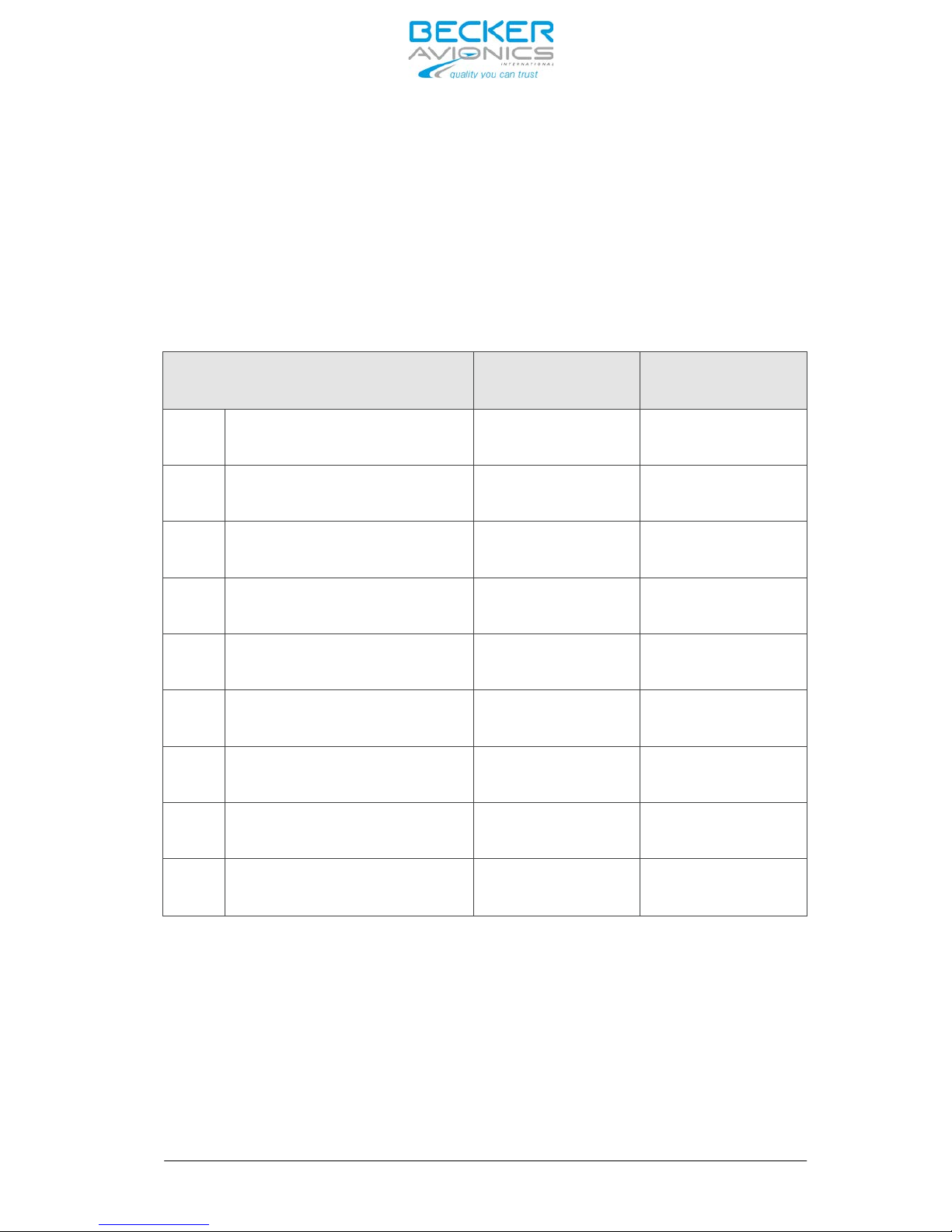
Winchman Individual VOX level adjust is performed via discrete control lines (#1)
If the VOX level push button is pressed for a short time (0.3s to ≤ 3s), the VOX level is increased
by one step, until the maximum value is reached. If the VOX level push-button is pressed for a
time ≥ 3s, the VOX level will be reset to the value set on the corresponding SW location.
•
lnput definition for VOX-level adjust line will be as follows:
- Single click:
Active LO, Input voltage ≤ 1 V (min. LO time 0.3 s, max. LO-time ≤ 2 s)
- Reset click:
Active LO, Input voltage ≤ 1 V (LO-time > 3 s)
•Generation of up to 8 different alert signals (1 continuous, 3 pulsed, 4 intermittent) in the
frequency spectrum of 1200 … 4800 Hz. The quantity is depending on the total of HOTMIKE lines used.
Both functions can not happen at the same time.
These alert tones are activated via 8 discrete control lines (active LO ≤ 1 V) and addition of
those signals to the summed IC audio signal.
Via configuration software it can be set which of the alert signals are:
- Muted individually in each
- Headset set at the priority level
- Set at cancellation possibility
•Interface facility for IC Amplifier Unit configuration.
•Initialization of a system selftest upon power-on (P_BIT) , a background test routine is continuously
running (C-BIT).
•Provision of 2 alternative internal operation voltage(s) from either of the airframe power supply buses.

Page
1-4
DV 64480.DIC.01 Issue 1 Sep./2013
IC6100
•Interface facility for IC Amplifier Unit configuration.
•Initialization of a system selftest upon power-on (P_BIT) , a background test routine is continuously
running (C-BIT).
•Provision of 2 alternative internal operation voltage(s) from either of the airframe power supply buses.
•Relay controlled fall-back in case of emergency operation (Back up): Fix 1 to headset 1, and Fix
2 to headset 2 (intercomunication between headset 1 and headset 2 remains) . Back-up
operation can be iniciated manually by using an external hard-wired switch, or automatically upon
power supply failure to the IC Amplifier Unit, or, if any internal power supply of the Unit itself is
defective.
The audio processing circuits are realized in a modular design.
Pict. 1: External Memory EM6100-(XXX)
The EM6100-(XXX) is the memory device (optional). It is a small device connected to the IC6100 and
stores all system configuration parameters. It allows a quick field replacement of the IC6100 without
reconfiguration when replacing by a new IC6100.
1.3.3 Memory device EM6100-(XXX)

DV 64480.DIC.01 Issue 1 Sep./2013 Page
1-5
IC6100
1.4 Identification of article
1.4.1 Types of Intercom Amplifier Unit
Intercom Amplifier Unit
IC 6100 -X-(XX)
1
2
Standard Configuration
Custom Configuration
0
1
EM6100-(XXX) is used
No EM6100-(XXX)
2 Equipped with 2 MIC/HEAD Boards
(operating with up to 4 Headset)
3 Equipped with 3 MIC/HEAD Boards
(operating with up to 6 Headset)
Identification number
IC Amplifier Unit

Page
1-6
DV 64480.DIC.01 Issue 1 Sep./2013
IC6100
1.5 Technical data
1.5.1 Power supply
Supply voltage (Bus) I 27.5 V DC nominal
18.0 V DC emergency
Supply voltage (Bus) II 27.5 V DC nominal
18.0 V DC emergency
Back-up voltage (Bus) 27.5 V DC nominal
18.0 V DC emergency
Current consumption (with 6 ACU’s) peak 3.0 A
average 1.5 A
1.5.2 Monitoring
1.5.2.1 Fixed inputs
Number
Sensitivity Channel 1....3
Sensitivity Channel 4....6
6
5 … 40 V adjustable (by software)
2.5 …20 V adjustable (by software)
600 Ω balanced / floating
≥ 70 dB
Impedance
Crosstalk attenuation between inputs
Muting during transmission ≥ 80 dB
1.5.2.2 Alert tone activation inputs
Number
Function
Input Current
8
active Low, ≤ 1.5 V
≤ 1 mA
Input
No.
Alert
tone
1
2400 Hz
continuous
2
1600 Hz
pulsed
3
2400 Hz
pulsed
4
3840 Hz
pulsed
5
1200
intermittent
6
2133
intermittent
7
3200
intermittent
8
4800
intermittent

DV 64480.DIC.01 Issue 1 Sep./2013 Page
1-7
IC6100
1.5.3 Headphone Amplifier
–Up to 6 ea.
Output power 250 mW (8.66 V) into 300 Ω or
500 mW into 8 Ω
or 2 x 250 mW into 2 x 8 Ω
balanced transformer output,
ungrounded
Distortion ≤ 2.5 % at 1 kHz
Frequency response
Signal-to-noise ratio
Main volume control range
300 Hz … 6 kHz (0/–3 dB)
≥ 70 dB
0 … -48 dB
2400 Hz
1600 Hz , 2400 Hz, 3840 Hz,
1200 Hz, 2133 Hz, 3200 Hz, 4800 Hz,
1600 Hz / 1200 Hz intermittent
1.5.4 Aural tone Generator
Continuous tone
Pulsed tones
Intermittent tones
Service tone 1 (Intercom request)
Service tone 2 (Emergency call 2400 Hz / 800 Hz / 1200 Hz intermittent
Pulsed means
Intermitted means
TON = T
OFF = 0.5
sec. 3 pulses 0.17sec, repetition rate 2.5 sec
active LO, ≤ 1.5 V
Activation (alert tone control lines)
Input current ≤ 1 mA

DV 64480.DIC.01 Issue 1 Sep./2013 Page
1-8
IC6100
50 … 400 mV nominal
150 Ω
12 V DC
1.5.5 Mike / AGC
1.5.5.1 Mike / AGC input (standard carbon mike)
Feed resistance 390 Ω
0.5 … 4 mV nominal
Sensitivity
Impedance
Excitation voltage (idle mode)
1.5.5.2 Mike input (Dynamic mic.)
Sensitivity
Impedance 20 Ω balanced / floating
1.5.5.3 Automatic Gain Control (AGC)
AGC threshold (adjustable) 80 … 150 mV (standard mike)
0.2 … 1 mV (dynamic mike)
Output regulation (∆ ue = +20 dB) ≤ +2 dB
1.5.5.4 Sidetone for IC
Sidetone level
0 dB... -15 dB selectable by SW
step 3 dB, standard - 6 dB
1.5.5.5 CVR connection
Channel 1 (Pilot)
Output voltage
Impedance 5 kΩ
Channel 2 (Copilot)
Output voltage
Impedance 5 k
Mike signal: 800 mV -1 dB / +3 dB
Headphone signal: -3 dB ref. Mike
Natural Mike + Headphone
Mike signal: 800 mV -1 dB / +3 dB
Headphone signal: -3 dB ref. Mike
Natural Mike + Headphone

Page 1-9 DV 64480.DIC.01 Issue 1 Sep./2013
IC6100
6
Active LO, ≤ 1.5 V
1.5.5.6 Control Inputs
(Discretes) Number
Activation
Input current 1 mA
Input No. Function
1 Winchmann VOX- level selection
2 Intercom request activation (1600 Hz / 1200 Hz intermitted)
3 Winchmann Volume level selection
4 Alert tone cancellation
5 SELCALL / Third intercom circuit activation
6 Emergency call activation (2400 Hz / 800 Hz / 1200 Hz inter-
mitted
1.5.5.7 Control outputs (discretes)
Number
Switch action
Switch capability
4
Active LO
27.5 V DC / 500 mA
Output No. Function
1 Not used
2 Cockpit CALL indication
3 Cabin CALL indication
4 3rd- IC-Circuit activation
1.5.5.8 Back-Up
monitor Number
Switch action
Normal Mode Output
1
Open contact 27.5 V / 500 mA
1.5.5.9 DC-output
DC output 27.5 V / 500 mA

DV 64480.DIC.01 Issue 1 Sep./2013 Page 1-10
IC6100
1.5.6 Intercom operation
Number of participants up to 6 clients directly connected (Can be
extended up to 12: 2 parallel HS at each port)
VOX threshold (adjustable by SW) 10 … 100 mV (standard mike)
50 … 500 µV (dynamic mike)
0.25 … 3 sec, adjustable
≤ 2.5 % at 1 kHz
300 Hz … 6 kHz (0/-3 dB)
≥ 60 dB
775 mV / 0 dBm
600 Ω (must be terminated at all times)
VOX hold time
Distortion
Frequency response
Signal-to-noise ratio
Input / output voltage on IC-Ring audio lines
Input / output impedance of IC-Ring audio lines
IC switch-off attenuation
Intercom circuits
Call activation
≥ 80 dB
cockpit-cabin / 3rd IC-Circuit / IC-Ring
discrete input
Call indication optical (CALL LED) and acousti-
cal ( 1600 Hz / 1200 Hz intermitted)
and discrete output
1.5.7 Build In Test Equipment (BITE)
1.5.7.1 Power On BuiId In Test (PBIT)
automatically after Power On
Activation
Coverage IC and EM6100 if
connected
Controllers and memories Aural
tone generator Headphone and
speaker Amps. Power supply
Duration max. 5 sec.
1.5.7.2 Continuous Build In Test
(CBIT) Activation Permanently active coverage
controllers and data transfer

Page
1-11
DV 64480.DIC.01 Issue 1 Sep./2013
IC6100
1.5.7.3 Build In Test Representation
The last 10 IBit results are stored in a non volatile memory and can be read out with the configuration
software. Its scope is mainly for technical repair and maintenance.
- manually activated
using external switch
1.5.7.4 Back-up operation -
Automatically activated
upon supply busses failure or
defection of internal power supply or
processor failure
Headset 1 - FIX 1, Headset 2- FIX 2
Fixed at 50%
Fixed input
Intercom level Headset 1, Headset 2
CVR level Fixed at 50%
1.5.8 Programming mode Interface
1.5.8.1 Programming mode Interface CAN Bus
1.5.9 Mechanical data
Length
Length
Width
Height
Weight
Mounting Case Material
338.50 mm ( IC6100-X-(XX) )
379.00 mm ( IC6100-X-(XX) )
57 mm
195 mm
≤ 3 kg
ATR Fixture, Weight < 500 g
AIMg, black
D-Sub 50-pin male shift lock
19pol male
Subminiatur 5-pole female
1.5.10 Unit connectors 2
pieces with Locking devices 1
piece bajonet
1 piece EM6100-(XXX))
- Connectors are coded against inadvertent misconnecting.......

DV 64480.DIC.01 Issue 1 Sep./2013 Page 1-12
IC6100
1.5.11 Environmental qualification (EUROCAE/RTCA
ED-14D/
DO-160E)
Environmental qualification for Intercom Amplifier Unit
Characteristic
ED-14E/DO-160E
Section Category Condition
Temperature / Altitude
4.0
D1
Low Ground Survival Temperature
4.5.1
D1
-55° C
Low Operating Temperature
4.5.1
D1
-40° C
High Ground Survival Temperature
4.5.2
D1
+85° C
High Short-Time Operating Temperature
4.5.2
D1
+70° C
High Operating Temperature
4.5.3
D1
+55° C
In-Flight Loss of Cooling
4.5.4
X
no auxiliary cooling required
Altitude
4.6.1
D1
50,000 ft.
Temperature Variation
5.0
B
5 °C per minute
Humidity
6.0
B
48 h at 65 °C at 95 % RH
Shock
7.2
B
6g in all directions
Crash Safety
7.3
B
20g shock; 20g accelaration
Vibration 8.0 S
U
M
G
Explosion Proofness
9.0
X
Water Proofness
10.0
X
Fluids Susceptibilities
11.0
X
Sand and Dust
12.0
X
Fungus Resistance
13.0
X
Salt Spray
14.0
X
Magnetic Effect
15.0
Z
less than 0.3 m
Power Input (DC)
16.0
B
Voltage Spike
17.0
A
Audio Frequency Conducted Susceptibility
18.0
B
Induced Signal Susceptibility
19.0
AC
Radio Frequency Susceptibility
20.0
WR
Emission of RF
21.0
M
Lightning Induced Transient Susceptibility
22.0
A3E3X
Lightning Direct Effects
23.0
X
Icing
24.0
X
Electrostatic Discharge (ESD)
25.0
A
Fire Flammability 26.0 X
1.6 Software
All data for IC Amplifier Unit are stored in the IC6100 itself and EM6100, if connected. If control elements on
the SW are altered, a data transmission immediately takes place to the IC Amplifier Unit. Saving the current
configuration is necessary for permanent validation. The software was classified as level C in accordance with
EUROCAE / RTCA document ED-12B / DO-178B.

Page 1-13 DV 64480.DIC.01 Issue 1 Sep./2013
IC6100
1.7 Approvals
- FAA
1.8 Scope of delivery
for operation with External memory device EM6100-(XXX)
1.9 Accessories (not contained in the scope of delivery)
- Mounting MT519-1 mod.1 for IC6100-X-(XX) Article-No.: 0890.790-261
- External memory device EM6100-(XXX) Article-No.: 0608.270-921
- Service Cable Kit 1K6100 Article-No.: 0608.750-276
Connector Kit CK 5101-C
consisting of:
- 19-pol. cable connector, crimp
- 50-pol. cable connector (2 ea.required)
- Crimp Coding pins ( 2 ea. required)
- Connector housing
- Two (2) Resistor metal film 121 Ohm
Article-No.: 0615.889-954
Article-No.: 0586.870-954
Article-No.: 0794.279-277
Article-No.: 0774.421-277
Article-No.: 0782.211-277
Article-No.: 0575.933-277
Article-No.: 0717.762-323
Option:
Article-No.:
0614.981-954
Connector Kit CK 5103-C (Manufacturer Commital)
consisting of:
CSW6100-2
configuration
software set
consisting of:
- CAN - USB -Adapter
- Code Meter Stick
Manuals
- 19-pol. cable connector, crimp
- 50-pol. cable connector (2 ea.required)
- Crimp Coding pins ( 2 ea. required)
- Connector housing
- Two (2) Resistor metal film 121 Ohm
Article-No.: 0615.005-277
Article-No.: 0774.421-277
Article-No.: 0782.211-277
Article-No.: 0575.933-277
Article-No.: 0717.762-323
Article-No.:
0608.602-919
- EASA
TSO-C139
ETSO-C139 (Pending)
Article-No.: 0925.702-921
Article-No.: 0925.703-921
- IC6100-2 (XX) Digital Intercom Unit (for max. 12 users)
- IC6100-3 (XX) Digital Intercom Unit (for max. 12 usesr)
Article-No.: 0900.149-071
Article-No.: 0900.150-071
- Installation and Operation DV 64480.DIC.01
- Maintenance and Repair DV 64480.DIC.02

Page
1-14
IC6100
BLANK
DV 64480.DIC.01 Issue 1 Sep./2013

Page 2-I
IC6100
Table of Contents
Section 2 INSTALLATION Page
2.1 2-1
2.1.1 2-1
2.2 2-1
2.3 2-1
2.4 2-1
2.5 2-2
2.5.1 2-2
2.6 2-3
2.7 2-5
2.8 2-6
2.8.1
General
Remark for the Intercom Amplifier Unit version IC6100-X-(110)
Inspection before installation
Continued Airworthiness
Mechanical installation
Aircraft wiring
General
Dimensions Intercom Amplifier Unit
Location of connectors
Connector Pin assignments
P1 - P2 D-Sub 50-pol. male, shift-lock connector 2-6
2.8.2 2-7
2.8.3 2-7
2.8.4 2-8
2.9 2-8
2.10 2-8
2.10.1 2-8
2.10.2 2-9
2-10
2-11
2.10.3
2.10.4
Fig. 2-1 2-3
Fig. 2-2 2-4
Fig. 2-3 2-5
Fig. 2-4 2-6
Fig. 2-5 2-8
Fig. 2-6 2-9
Fig. 2-7 2-10
Fig. 2-8 2-11
Installation dimensions (measures in mm)
Mounting Intercom Amplifier Unit
Physical locations of connectors
Logical pin assignment
Power connections
Audio and CVR connections
Fix audio and IC ring connections
Interwiring diagram Control and other connections
DV 64480.DIC.01 Issue 1 Sep./2013
Becker-Bus System, B-Bus connector
Address coding for J5 (IC)
Pin connections of the unit connector J6 (EM6100-(XXX))
Configuration software
Interwiring diagrams
Interwiring diagram Power connections
Interwiring diagram Audio and CVR connections
Interwiring diagram Fx audio and IC ring connections
Interwiring diagram control and other connections

Page 2-II
IC6100
BLANK
DV 64480.DIC.01 Issue 1 Sep./2013
This manual suits for next models
1
Table of contents
Other Becker Amplifier manuals