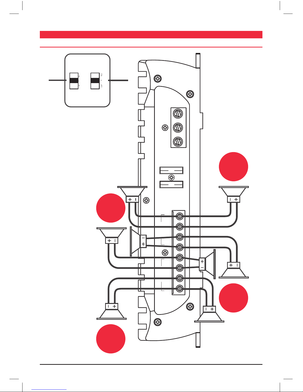
GME GA9800 User manual

INSTRUCTION MANUAL
GA9800
4 CHANNEL
AMPLIFIER

PAGE 2 INSTRUCTION MANUAL GA9800
CONTENTS
GME STRONGLY RECOMMENDS THAT YOU KEEP THIS MANUAL
IN A SAFE PLACE FOR FUTURE REFERENCE
ACCESSORIES SUPPLIED . . . . . . . . . . . . . . . . . . . . 2
INTRODUCTION ..........................2
FEATURES ..............................2
PROTECTION CIRCUITRY . . . . . . . . . . . . . . . . . . . 2
2OHMPROTECTION ......................3
ELECTRICAL WIRING . . . . . . . . . . . . . . . . . . . . . . 3
FUSES .................................3
MOUNTING THE AMPLIFIER . . . . . . . . . . . . . . . . . 3
POWER SUPPLY CONNECTIONS . . . . . . . . . . . . . . 3
FOUR CHANNEL INSTALLATION WIRING
1. Low input wiring 2 channel ................4
2.Highinputwiring .......................5
3. Low input wiring 4 channel ................6
SPEAKER CONFIGURATION
1.4/8-wayspeaker........................7
2. 2-way speaker and subwoofer ..............8
3. 2-way speaker and 2-way subwoofer.........9
4. 4-way speaker and 2-way subwoofer.........9
AMPLIFIER INSTALLATION..................10
REMOTECONTROL ......................10
PRECAUTIONS ..........................10
SPECIFICATIONS .........................10
TROUBLESHOOTING ......................11
WARRANTY ...................... BackPage
INTRODUCTION
Congratulations on your purchase of the GME GA9800
marine audio amplifier.
This amplifier is designed to the highest level of quality and
will offer you years of listening enjoyment.
Thank you for making GME your choice for marine audio
equipment.
FEaTURES
• Thermal/Short/Over Load Protection
• 2 Ohm stable (4 Ohm bridged)
• P.W.M.MOSFET power supply
• Power and distress indicator
• Variable low-pass (50–120 Hz)
• Heavy duty heat sink
• Adjustable input sensitivity
• Soft delayed remote turn-on
• Low level and high level input
• Nickel plated terminal strips/RCA jacks
• Built-in remote jack
• Built-in electronic Crossover and an adjustable
Low Pass Control
• Designed with 100% MOSFET Power supply, ensuring
extremely quick switching response and self-protection.
PROTECTION CIRCUITRy
The amplifier protection circuitry will disable the amplifier if
input overload, short circuit or extremely high temperature
conditions are detected. When the protection mode is in
operation, the LED indicator on the front panel will be
illuminated, indicating the amplier has gone into a
self-preservation mode.
lf you observe that the protection LED is lit, please check
the system carefully to determine what has caused the
protection circuit to engage. The amplifier can be reset by
turning the remote power OFF and then ON again. lf the
amplier shuts down due to a thermal overload condition,
please allow it to cool down before restarting. lf the shut
down is due to an input overload or short circuit, be sure
to repair these conditions before attempting to power up
the amplifier again.
aCCESSORIES SUPPlIED
• Subwoofer wire
• Remote Control
• Mounting screws
• Allen keys
• Instruction Manual
If any items are missing or
damaged, please contact your
retailer or place of purchase.

GA9800 INSTRUCTION MANUAL PAGE 3
2 Ohm PROTECTION
Your GME GA9800 amplifier is designed to operate
efficiently at loads down to 2 Ohm. You can install four
8 Ohm speakers per channel when using parallel wiring,
increasing the number of woofers per channel at low
frequencies [up to 100 Hz]. This produces an acoustic
coupling effect, increasing your power output by 3 dB
per speaker, or the equivalent of additional 10W to
each speaker.
When operating at 2 Ohm, the amplier will increase its
output power by approximately 50%. The current draw will
also increase by about the same amount, so be sure you
have enough current to run the amplifiers into a 2 Ohm
load, lf you lack adequate current, your music reproduction
will be distorted.
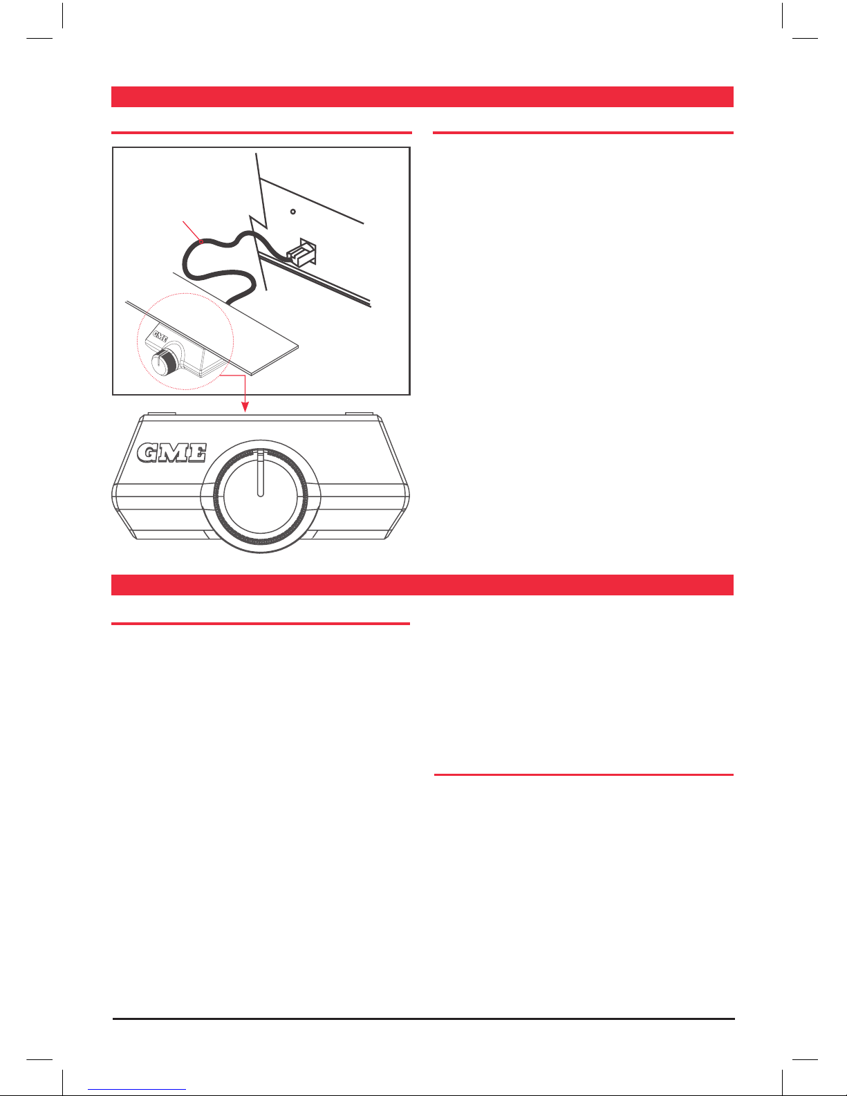
Note: The gain control of any audio amplifier should not be
mistaken for a volume control. lt is a sophisticated device,
designed to match the output level of your audio source
unit to the input level of the amplifier. Do not adjust this
input level to maximum unless your input level requires it.
lgnoring these instructions will result in an input overload
to the amplier, and excessive audio distortion. lt can also
cause the protection circuit to engage.
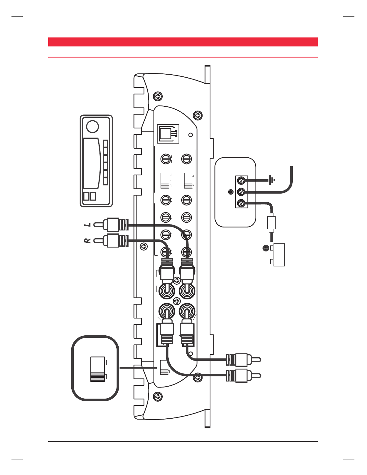
ElECTRICal wIRINg
Your GME amplifier is equipped with easy top-access screw
terminals. These terminals are NICKEL Plated in order to
ensure excellent electrical contact, and to resist corrosion.
When making electrical connections to the amplier,
please observe the following:
• Use at least 4 gauge or heavier wires for power and
ground connections.
• Wire the amplier directly to the battery.
• For the ground connection, use the shortest possible wire
to a good chassis ground point.
• Wire the remote connection to the auto start lead of
your stereo.
FUSES
Power fuses protect both the amplifier and the electrical
system of your vessel from fault conditions. lf you must
replace the fuse in your amplier, use a fuse of exactly the
same type and rating. A different type or rating of fuse may
result in damage or fire.
mOUNTINg ThE amPlIFIER
Mark the location for the mounting screw holes by
positioning the amplifier where you wish to install it and
use a scribe [or one of the mounting screws] inserted in
each mounting hole to mark the mounting surface. lf the
mounting surface is carpeted, measure the hole centres
and mark with a felt tip pen.
Drill pilot holes in the mounting surface for the mounting
screws and insert the mounting screws into these holes.
Tighten them securely.
Note: Be sure to take note of any wires, lines or other
devices in your vessel which may be located behind any
mounting surface!
POwER SUPPly CONNECTIONS
The GA9800 amplifier is designed to work within 10 to
16 Volts DC. Before any wires are connected, the vessel’s
electrical system should be checked for correct voltage
supply with the help of a volt meter.
1. Check the voltage at the battery terminals with the
ignition in the OFF position. The Volt Meter should
read no less than 12 Volts.
2. Check the battery with the engine running between
1500 and 2000 rpms. The Volt Meter should now read
between 13.5 and 14.5 Volts.
Note: lf your vessel’s electrics are not up to these
specications, we recommend it to be checked by an
Marine Electrician before you continue with the installation.

PAGE 4 INSTRUCTION MANUAL GA9800
4 ChaNNEl INSTallaTION wIRINg
1. LOW INPUT WIRING CONFIGURATION 2 CHANNEL
POWER
+12V GNDREM
3/4CH
160HZ
REM
8V 0.3V 0dB 20HZ 55HZ 40HZ 40HZ
600HZ+18dB HP LPFULL
1/2CH 40HZ 160HZ
8V 0.3V 0dB 20HZ 55HZ 40HZ 1KHZ
+18dB
PRT
HP LPFULL
3/4CH
LEVEL BASS SUB
HP LP
LP
X-OVER
X-OVER
SONICBOOST
LEVEL BASS SUB
HP
SONICBOOST
R2CH
1CH 3CH
4CH
OUTPUT INPUT
PWR
1+ 1- 2- 2+
3+ 3- 4- 4+
INPUTSHIGH
2CH 4CH
INPUT MODE
2CH 4CH
INPUT MODE
Switch in 2CH Position To Audio Outputs of head unit or signal
processor with Stereo Inputs.
Chassy ground point
To Remote Turn-On terminal
of head unit.
To inputs of
Satellite Amplifier. Fuse
Battery
INPUT MODE
SWITCH SETTING

GA9800 INSTRUCTION MANUAL PAGE 5
2. HIGH INPUT WIRING CONFIGURATIONS 2/4 CHANNEL
3/4CH
160HZ
REM
8V 0.3V 0dB 20HZ 55HZ 40HZ 40HZ
600HZ+18dBHP LPFULL
1/2CH 40HZ 160HZ
8V 0.3V 0dB 20HZ 55HZ 40HZ 1KHZ
+18dB
PRT
HP LPFULL
3/4CH
LEVEL BASS SUB HP LP
LP
X-OVER
X-OVER
SONICBOOST
LEVEL BASS SUB
HP
SONICBOOST
R2CH
1CH 3CH
4CH
OUTPUT INPUT
PWR
1+ 1- 2- 2+
3+ 3- 4- 4+
INPUTSHIGH
2CH 4CH
INPUT MODE
3+ 3- 4- 4+ 1+ 1- 2- 2+
HI-INPUTS HI-INPUTS
Chassis GND
Chassis GND
1+
3+
2–
4–
1–
3–
2+
4+

PAGE 6 INSTRUCTION MANUAL GA9800
3. LOW INPUT WIRING CONFIGURATION 4 CHANNEL
POWER
+12V GNDREM
3/4CH
160HZ
REM
8V 0.3V 0dB 20HZ 55HZ 40HZ 40HZ
600HZ+18dB HP LPFULL
1/2CH 40HZ 160HZ
8V 0.3V 0dB 20HZ 55HZ 40HZ 1KHZ
+18dB
PRT
HP LPFULL
3/4CH
LEVEL HP LP
LP
X-OVER
X-OVER
LEVEL BASS SUB
HP
SONICBOOST
R2CH
1CH 3CH
4CH
OUTPUT INPUT
PWR
1+ 1- 2- 2+
3+ 3- 4- 4+
INPUTSHIGH
2CH 4CH
INPUT MODE
2CH 4CH
INPUT MODE
BASS SUB SONICBOOST
Switch in 4CH Position
To Audio Outputs of head unit or signal
processor with Four Channel Outputs.
Chassy ground point
Fuse
Battery
INPUT MODE
SWITCH SETTING
To Remote Turn-On terminal
of head unit.

GA9800 INSTRUCTION MANUAL PAGE 7
FUSE
CH1+ CH1- CH2+ CH2- CH3+ CH3- CH4+ CH4-
BRIDGED
SPEAKERS
BRIDGED
POWER
+12V GNDREM
25
25
HP LPFULL
HP LPFULL
X-OVER
X-OVER
Due to 2 Ohm amplier stability, each speaker port can carry
an extra set of 4 Ohm speakers as shown.
CH 3/4 Crossover Mode switch in
Full Range position.
CH 1/2 Crossover Mode
switch in Full Range position.
GME
4 Ohm
speaker
GME
4 Ohm
speaker
GME
4 Ohm
speaker
GME
4 Ohm
speaker
LEFT SPEAKER
LEFT SPEAKER
FRONT SPEAKERS
REAR SPEAKERS
CROSS OVER
SWITCH SETTINGS
RIGHT SPEAKER
RIGHT SPEAKER
SPEaKER OUTPUT CONFIgURaTION
1. 4/8-WAY SPEAKER CONFIGURATION

PAGE 8 INSTRUCTION MANUAL GA9800
2. 2-WAY SPEAKER AND SUBWOOFER CONFIGURATION
40HZ 160HZ
LP
REM
PRT
FUSE
CH1+ CH1- CH2+ CH2- CH3+ CH3- CH4+ CH4-
BRIDGED
SPEAKERS
BRIDGED
POWER
+12V GNDREM
25
25
HP LPFULL
HP LPFULL
X-OVER
X-OVER
CH 3/4 Crossover Mode switch in
Low Pass position.
CH 1/2 Crossover Mode
switch in High Pass position.
GME
4 Ohm
speaker
GME
4 Ohm
speaker
GME
Subwoofer
4 Ohm
LEFT SPEAKER
CROSS OVER
SWITCH SETTINGS
CH3/4 REMOTE
SUBWOOFER
LEVEL CONTROL
RIGHT SPEAKER
SUBWOOFER

GA9800 INSTRUCTION MANUAL PAGE 9
4. 4-WAY SPEAKER AND 2-WAY SUBWOOFER CONFIGURATION
FUSE
CH1+ CH1- CH2+ CH2- CH3+ CH3- CH4+ CH4-
BRIDGED
SPEAKERS
BRIDGED
POWER
+12V GNDREM
25
25
GME
Subwoofer
4 Ohm
GME
Subwoofer
4 Ohm
GME
4 Ohm
speaker
GME
4 Ohm
speaker
GME
4 Ohm
speaker
GME
4 Ohm
speaker
4 CHANNEL
AMPLIFIER
TRI-MODE ALL
4 CHANNELS.
all CROSSOvER
SETTINgS IN ThIS
mODE ShOUlD
bE FUll RaNgE.
GME recommends the
following component values
for 12 dB Passive Crossover.
FREQUENCY
INDUCTOR CAPACITOR
140 Hz 6.5 mH 220 uF
LEFT
SPEAKER
LEFT
SPEAKER
FRONT SPEAKERS
REAR SPEAKERS
RIGHT
SPEAKER
RIGHT
SPEAKER
Low Pass filter inductor
High Pass filter capacitors
FRONT SUBWOOFER
REAR SUBWOOFER
HP LPFULL
HP LPFULL
X-OVER
X-OVER
3. 2-WAY SPEAKER AND 2-WAY SUBWOOFER CONFIGURATION
40HZ 160HZ
LP
REM
PRT
HP LPFULL
HP LPFULL
X-OVER
X-OVER
FUSE
CH1+ CH1- CH2+ CH2- CH3+ CH3- CH4+ CH4-
BRIDGED
SPEAKERS
BRIDGED
POWER
+12V GNDREM
25
25
CH 3/4 Crossover Mode switch
in Low Pass position.
CH 1/2 Crossover Mode
switch in Full Range position.
Min. Speaker
Impedance
4–8 Ohms
GME
Subwoofer
4 Ohm
GME
Subwoofer
4 Ohm
GME
4 Ohm
Speaker
GME
4 Ohm
Speaker
CROSS OVER
SWITCH SETTINGS
CH3/4 REMOTE
SUBWOOFER
LEVEL CONTROL
4 CHANNEL AMPLIFIER
TRI-MODE CHANNEL 1 & 2
BRIDGED MONO FOR CHANNEL 3 & 4.
LEFT
SPEAKER
FRONT SPEAKERS
RIGHT
SPEAKER
Low Pass filter inductor
High Pass filter capacitors
SUBWOOFER
SUBWOOFER

PAGE 10 INSTRUCTION MANUAL GA9800
SPECIFICaTIONS
GENERAL
Max. Power @ 2 Ohm: 4 x 367 Watts
RMS Power @ 4 Ohm: 4 x 65 Watts
Bandwidth: 10 Hz – 40 kHz
Signal to Noise: ≥ 95 dB
Channel Separation: ≥ 60 dB
Input Sensitivity Range: 300 mV – 8V
LP Variable Crossover: 40 – 160 Hz & 12 dB/octave
HP Variable Crossover: 40 – 600 Hz/ 1 kHz &
12 dB/octave
Variable Bass Boost: 0 – +18 dB & 45 Hz
Variable Subsonic Filter: 20 – 55 Hz & 12 dB/octave
Phase: No
RCA Input Model: Yes
Input Impedance: 20 K Ohm
Damping Factor: ≥ 200
T.H.D (4 Ohm): 0.05%
Fuse Rating: 2 x 25 Amp
PHYSICAL
Dimensions: 254 mm (10”) (W)
x 56 mm (2.2”) (H)
x 381 mm (15”) (D)
*All specifications are typical and subject to change without notice or obligation
amPlIFIER INSTallaTION
SUBWOOFER REMOTE CONTROL PRECAUTIONS
Before you drill or cut any holes, investigate your vessel’s
layout very carefully. Take care when you work near the gas
tank, fuel lines, hydraulic line and electrical wiring.
Do not operate the amplifier when it is unmounted. Attach
all audio system components securely within the vessel.
Do not mount this amplifier so that the wire connections
are unprotected or in a pinched condition, or likely to be
damaged by nearby objects.
Before making or breaking power connections in your
system, disconnect the vessel’s battery. Conrm that
your head unit or other equipment is turned OFF while
connecting the input jacks and speaker terminals.
lf you need to replace the power fuse, only replace it with a
fuse identical to that supplied with the system. Using a fuse
of a different type or rating may result in damage to your
system which isn’t covered by the manufacturer’s warranty.
REMOTE
LINE CODE

GA9800 INSTRUCTION MANUAL PAGE 11
TROUblEShOOTINg
No output 1. Confirm all terminal strip connections are secure and tight.
2. Check both in-line and built-in fuses. Both the ‘+ 12V’ and the ‘REMOTE’ terminal
must have + 12V referenced to chassis ground.
3. Conrm the audio signal source [radio, equalizer, etc.] is connected and is supplying
output signal. To check if the amplier is supplying signal, unplug the RCA cables from
the signal source [but leave them plugged into amp]. Briey tap the centre pin of each
of the disconnected RCA plugs with your nger. This should produce a noise [feedback]
in your speakers.
Only 1 Channel is working 1. Confirm all speaker strip connections are secure and tight.
2. Check the ‘BALANCE’ control on the head unit [or other source] to verify that it is set
to its midpoint.
3. If you are using the Low Level RCA input, reverse the input plugs at the amplier
[switch the R with the L]. If the channel which is silent switches to the other side,
the problem is either in the head unit/other source or the connecting cables.
Weak output Re adjust the Input Sensitivity Control to better suit input signal.
Noise in the audio 1. If the noise is a ’whine’ whose pitch follows the engine speed, conrm that the
amplier and any other signal sources [head unit, etc.] are properly grounded.
2. If the noise is a ‘clicking’ or ‘popping’ noise whose rate follows the engine speed,
this usually means the vessel is equipped with resistor spark plugs and wires, or that
the ignition is in need of service.
3. Check the routing of the speaker and input wires to make sure they are not adjacent
to wires which interconnect lights and other accessories. If the above steps fail to
improve or clear noise interference, the system should be checked by a professional
marine audio installer.
PROblEm ChECK ITEm/SOlUTION
PLEASE NOTE: Before moving your amplier, refer to the list below and follow the suggested procedures. ALWAYS test the
speakers and their connecting wires first.

Part Number: 310442 Drawing Number: 44405-1 INSTRUCTION MANUAL GA9800
A Division of
Standard Communications Pty. Ltd.
Head Office: SYDNEY- Locked Bag 2086, North Ryde, NSW 1670, Australia. Tel: +61 (0)2 9844 6666 Fax : +61 (0)2 9844 6600
MELBOURNE ADELAIDE PERTH BRISBANE SYDNEY AUCKLAND
7 Micro Circuit Unit 1 Unit 1 Unit 1 Unit B Unit F
DANDENONG STH 3165 14 Phillips Street 10-12 Harvard Way 89-101 Factory Road 22-24 College Street 35 Neil Park
Tel: (03) 9798 0988 THEBARTON 5031 CANNING VALE 6155 OXLEY 4075 GLADESVILLE 2111 GREENMOUNT NZ
Fax: (03) 9798 0177 Tel: (08) 8234 2633 Tel: (08) 9455 5744 Tel: (07) 3278 6444 Tel: (02) 9879 8888 Tel: (09) 274 0955
Fax: (08) 8234 5138 Fax: (08) 9455 3110 Fax: (07) 3278 6555 Fax: (02) 9816 4722 Fax: (09) 274 0959
For customers outside Australia and New Zealand please contact your local GME Distributor or email: export@gme.net.au
Web Site: www.gme.net.au
STaNDaRD COmmUNICaTIONS CONTRaCT waRRaNTy
1. STATUTORY WARRANTIES
1.1 The Trade Practices Act Part V, Division 2A and other legislation
imply conditions, warranties and other obligations on us to
consumers that cannot be excluded, restricted or modified.
Those provisions apply to the extent required by law.
1.2 We exclude all other conditions, warranties and obligations
which would otherwise be implied concerning the activities
covered by this agreement.
1.3 We limit our liability where we are allowed to do so. Examples
of where we are allowed to limit liability are -
(a) you acquire goods from us for re-supply;
(b) the goods or services we supply are not of a kind ordinarily
acquired for personal, domestic or household use
or consumption.
1.4 Where we are allowed to limit our liability, to the extent
permitted by law, our sole liability for breach of a condition,
warranty or other obligation implied by law is limited -
(a) in the case of goods we supply, to any one of the following
as we decide -
(i) the replacement of the goods or the supply of
equivalent goods;
(ii) the repair of the goods;
(iii) the payment of the cost of repairing the goods or of
acquiring equivalent goods;
(iv) the payment of the cost of having the goods
repaired; or
(b) in the case of services we supply, to any one of the
following as we decide -
(i) the supplying of the services again;
(ii) the payment of the cost of having the services
supplied again.
2. ADDITIONAL WARRANTIES
2.1 The warranties in this clause are in addition to the statutory
warranties referred to in the previous clause.
2.2 We warrant our goods to be free from defects in materials
and workmanship for one year from the date of original
sale (or another period we agree to in writing). During this
period and as our sole liability to you under this warranty,
we agree to, at our option, either repair or replace goods
which we are satisfied are defective. We warrant
replacement parts for the remainder of the period
of warranty for the goods into which they
are incorporated.
2.3 We warrant our other repairs to be free from defects in
materials and workmanship for three months from the
date of the original repair. During this period and as
our sole liability to you for the repair, we agree to
repair or replace (at our option) repaired goods which
we are satisfied are defective.
2.4 We warrant that we will perform services with
reasonable care and skill and agree to investigate
any complaint made in good faith that we have
performed services unsatisfactorily. If we are satisfied
that the complaint is justified, and as our sole liability
to you under this warranty, we agree to supply those
services again at no extra charge to you.
2.5 If you want warranty service under this clause you
must give us an original or copy of the sales invoice
from the transaction or some other evidence showing
details of the transaction.
3. OTHER LIMITATIONS
3.1 You may not rely on any representation, warranty or
other provision by or for us which is not covered by
clause [ 1 ] or repeated in this agreement in clear
terms.
3.2 We are not liable (nor are our employees, contractors
and agents) for any damage, economic loss or
loss of profits whether direct, indirect, general, special
or consequential -
(a) arising out of any breach of any implied or
express term, condition or warranty; or
(b) suffered as a result of our negligence (or that
of our employees, contractors or agents)
- apart from liability as set out in the previous
two clauses.
3.3 The liability of a party under this agreement (whether
arising in contract, tort or by statute) is to be reduced
by the same proportion as represents the proportion
of the loss or damage caused or contributed to by the
other party, its contractors or agents.

INSTRUCTION MANUAL
GR200
AM/FM/VHF MARINE
BROADCAST RADIO
INNOVATIVE ELECTRONICS

Page 2 INSTRUCTION MANUAL GR200
FEATURES ........................................................ 3
ACCESSORIES ..................................................... 3
COMPLIANCE ..................................................... 4
LISTENING TO FM IN YOUR BOAT ...................................... 4
LCD DISPLAY ...................................................... 4
CONTROLS ....................................................... 5
Power Key .................................................... 5
Mode Key .................................................... 5
Band Key ..................................................... 5
Up/Down Keys ................................................. 6
Memory Keys .................................................. 6
OPERATION ...................................................... 6
Turning the GR200 ON and OFF .................................... 6
Adjusting the Sound. . . . . . . . . . . . . . . . . . . . . . . . . . . . . . . . . . . . . . . . . . . . . 6
Tuning for Stations .............................................. 8
Memory Keys .................................................. 9
Automatic Memory Storage ....................................... 9
Local/DX Mode ............................................... 10
Stereo/Mono Mode ............................................ 10
INSTALLATION ................................................... 10
Mounting the GR200 ........................................... 11
Electrical Wiring ............................................... 12
SPECIFICATIONS .................................................. 14
STANDARD COMMUNICATIONS CONTRACT WARRANTY. . . . . . . . . . . . . . . . . . . . 15
BRANCH ADDRESSES ....................................... BACK PAGE
CONTENTS

Page 3GR200 INSTRUCTION MANUAL
FEATURES
• Compact design with bracket or flush mounting options
• Ingress Protection to IP55*
• 7 bands (LW, SW, AM1, AM2, FM1, FM2, VHF)
• 6 preset frequency memories per band
• Simple push button controls.
• Front panel ‘monitor’ speaker
• Large white backlit display with ‘dim’ feature
• FM stereo reception
• Bass, treble and balance controls
• Separate bass and treble memories for each band
• Over voltage indicator
• Reverse polarity protection
• Static discharge protection at antenna input
• User selectable VHF frequencies and NOAA weather channels
• Auxiliary audio input
• Available in black or white
ACCESSORiES
Supplied
2 x extension speaker leads - 3.5 mm mini jack
Mounting bracket, gimbal knobs and stainless steel screws
DC supply lead
Instruction manual
Optional
In-dash flush mounting kits – MK100W (white), MK100B (black), MK002W, MK002B.
Rear flush mount kit – MK600
Choose from a range of GME antennas
Choose from a range of GME speakers
Cabin cover – CVR001W (white), CVR001B (black).
Auxiliary input interface cable - LE74
*Refer: www.gme.net.au/IPRatings

Page 4 INSTRUCTION MANUAL GR200
COMPLiANCE
This device complies with AS/NZS 61000.6.3:2007
This device complies with part 15 of the FCC rules. Operation is subject to the condition
that this device does not cause harmful interference.
LiSTENiNG TO FM iN YOUR BOAT
The majority of FM broadcasts are music programs. Compared with AM signals, FM
signals have a wider dynamic range, are relatively immune to noise and provide virtually
distortion free music reproduction. However, because of the nature of FM signals and
the fact that FM stations are usually positioned for shore based reception, reception in a
moving boat may be accompanied by problems.
FM programs are broadcast for local reception and may not be heard satisfactorily at
distant locations. To enjoy FM programs at their best, it is important that you tune to a
station that is broadcasting in your locality.
FM signals can reflect from solid objects such as buildings or hills. If these reflected
signals are received along with signals that are arriving directly from the transmitter, they
may mix together to produce what is known as ‘multipath distortion’. This distortion is
heard as noise. Often, moving as little as one metre from your position will correct
this problem.
FM signals travel in straight lines. Because the signals are reflected from or absorbed by
large solid objects, a signal ‘shadow’ may be present behind the object which may result
in poor reception in that area.
LCD DiSPLAY
VHF Channels Memory Number
Band Selection Modes
Frequency
Weather Channels
Auxiliary Input

Page 5GR200 INSTRUCTION MANUAL
CONTROLS
POWER KEY
Press and hold the Power key to turn the GR200 ON or OFF. While the radio is ON
briefly press the Power key to toggle the audio mute function. ‘MUTE’ will flash on the
display when the mute function is activated.
MODE KEY (M)
The Mode key provides access to the Volume, Bass, Treble, Balance, Frequency Adjustment,
Automatic Memory Store (AMS) and Local/DX settings.
The Mode selection will automatically return to the Volume setting 20 seconds after the
last key press.
BAND KEY (B)
The GR200 has 7 selectable frequency bands plus an Auxiliary audio input. The frequency
bands available are Long Wave (LW), Short Wave (SW), AM (AM1 and AM2), FM (FM1
and FM2) and VHF Marine (VHF). The Auxiliary input mode allows audio from external
sources such as MP3 players to be connected via a 3.5 mm socket lead on the rear panel.
The frequency coverage of each band is listed in the specifications on page 14 of
this manual.
Speaker
LCD Display Mode Key
Up Key
Down Key
Band Key
Memory Keys Power/Mute Key
M
B

Page 6 INSTRUCTION MANUAL GR200
UP/DOWN KEYS
The Up and Down keys are used to adjust functions selected using the Mode key.
MEMORY KEYS
Six memory keys are provided for storage and retrieval of station memories.
OPERATiON
TURNING THE GR200 ON AND OFF
To switch the GR200 on, press and hold the key for two seconds.
The radio will turn ON.
To switch the GR200 off, press and hold the key for two seconds.
The radio will turn OFF.
Note: When the GR200 is switched off or the power is interrupted, it will remember the
last state that it was set to and return to that state when it is switched back on.
ADJUSTING THE SOUND
Adjusting the Volume
During normal use, the GR200 will default to the volume mode. Whenever the volume
mode is selected ‘VOL’ is displayed on the right of the LCD. If you are not in the volume
mode, briefly press the Mode key repeatedly until ‘VOL’ is displayed on the LCD.
To adjust the volume, press the or key. Pressing the key will increase the volume
while pressing the key will decrease the volume. The volume setting will be displayed
on the LCD. Minimum volume setting displays a value of 0 with a maximum volume
setting of 30. To quickly adjust the volume setting, press and hold the or key.
Adjusting the Bass
To select the bass mode, briefly press the Mode key repeatedly until BAS is displayed on
the right of the LCD. To adjust the bass, press the or key. Pressing the key will
increase the bass while pressing the Key will decrease the bass. The bass setting will
be displayed on the LCD. Minimum bass setting displays a value of -7 with a maximum
bass setting of +7. A setting of 0 indicates a flat bass response. To quickly adjust the bass
setting, press and hold the or key.

Page 7GR200 INSTRUCTION MANUAL
Adjusting the Treble
To select the treble mode, briefly press the Mode key repeatedly until ‘TRE’ is displayed
on the right of the LCD. To adjust the treble, press the or key. Pressing the key
will increase the treble while pressing the key will decrease the treble. The treble
setting will be displayed on the LCD. Minimum treble setting displays a value of -7 with
a maximum treble setting of +7. A setting of 0 indicates a flat treble response. To quickly
adjust the treble setting, press and hold the or key.
Adjusting the Balance
The balance setting controls the audio balance between the left and right speaker.
Note: The balance mode is only available when the external speakers are attached. If
running the GR200 from the internal monitor speaker, the balance function is skipped
when the Mode key is pressed.
Briefly press the Mode key repeatedly until ‘BAL’ is displayed on the right of the LCD.
To adjust the Balance, press the or key. Pressing the key will adjust the balance
towards the left speaker while pressing the Key will adjust the Balance towards the
right speaker. The Balance setting will be displayed on the LCD. Full left balance displays a
value of L10 with a full right balance setting of R10. A setting of 0 indicates the balance
is set equally between both speakers. To quickly adjust the Balance setting, press and
hold the or key.
Muting the Sound
The Mute feature allows the radio’s sound to be temporarily disabled without affecting
any other settings. This is useful when making calls on your two way radio or mobile
phone or during a local conversation where the radio sound is distracting.
To temporarily mute the radio, briefly press the key. The audio will be temporarily
disabled and no sound will be heard from the speaker(s). While the sound is muted,
‘MUTE’ will flash on the display.
To cancel the Mute selection and restore the sound to its previous level, briefly press the
key again.
Dimming the Display
The display lighting can be dimmed for night time viewing. The default setting is
maximum brightness. To dim the display:
1. Press and hold the key to turn the GR200 OFF.
2. Now press and hold the key again. The GR200 will turn on. DON’T RELEASE THE
KEY YET.
3. Now briefly press the M key to toggle the display lighting dim or bright. Once you
have selected the display lighting you can release the key.

Page 8 INSTRUCTION MANUAL GR200
TUNING FOR STATIONS
Selecting the Frequency Band
The GR200 has 7 selectable frequency bands plus an Auxiliary audio input. The frequency
bands available are Long Wave (LW), Short Wave (SW), Medium Wave (AM1 and AM2),
FM (FM1 and FM2) and VHF Marine (VHF). The Auxiliary input mode allows audio from
external sources such as MP3 players to be connected via a 3.5 mm socket lead on the
rear panel.
To select the desired frequency band (or the Auxiliary input) briefly press the Band key.
Each press will advance to the next band in the sequence and the corresponding symbol
LW, SW, AUX, AM1, AM2, FM1, FM2 or VHF will appear on the display to confirm your
selection. Note that when the AUX input is selected, ‘In’ will also be displayed when an
external device is connected.
The frequency coverage of each band is listed in the specifications on page 14 of this
manual. For information on the ‘AUX’ selection please see ‘Auxiliary Input’ on page 13.
Selecting USA or European Receiver Standards
The GR200 supports USA, Canadian and European standards for AM and FM reception.
Australian models conform to the European standard and are set that way by default.
Owners in the USA or Canada should select the USA or Canadian standard.
To switch between the standards, press and hold the Band key for 3 seconds. The GR200
will display ‘E’ at the top of the display for European, ‘U’ for USA or ‘C’ for Canada. The
‘E’, ‘U’ or ‘C’ symbols will disappear once any of the memory preset buttons are pressed.
The differences between the European, USA and Canadian bands are listed in the
specifications on page 14 of this manual.
Note: When the VHF marine band is selected, switching between USA, Canadian and
European standards will also select USA , Canadian or International VHF marine
channel allocations.
Manually Tuning the Frequency
Briefly press the Mode key repeatedly until ‘FREQ’ is displayed on the right hand side
of the LCD. You can now manually change the frequency. To adjust the frequency, briefly
press the or key. Pressing the key will increase the frequency while pressing the
Key will decrease the frequency. The frequency will be displayed on the LCD.
Scanning for Stations
While in frequency tuning mode, press and hold the or key for 3 seconds. The
GR200 will automatically scan upwards or downwards in frequency starting at the
present frequency. When a station is found, scanning will stop on that frequency.
Note: When tuning in the VHF band, standard VHF marine channel numbers 1-28 and 60-88
are displayed. If the USA or Canadian standard is selected, an additional ten NOAA weather
channels are also available. When these are selected, ‘WEATHER’ is displayed on the LCD.
Other manuals for GA9800
1
Table of contents
Other GME Amplifier manuals
Popular Amplifier manuals by other brands

Balanced Audio Technology
Balanced Audio Technology VK-150 owner's manual

Phoenix Gold
Phoenix Gold MPS2240 manual

Rolls
Rolls PM60 Connection guide

Televes
Televes Avant HD quick guide

Gallien-Krueger
Gallien-Krueger Legacy Series owner's manual

Rockford Fosgate
Rockford Fosgate T400X2ad Installation & operation