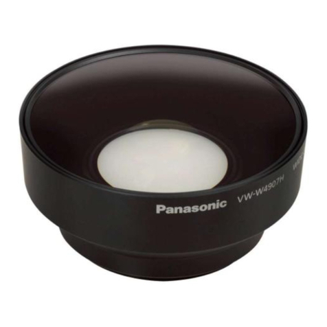
Beckhoff VOS2000-0625 User manual

Manual | EN
VOS2000-0625
Industrial-grade high-resolution C-mount lens
11/11/2022 | Version: 1.0


Table of contents
VOS2000-0625 3Version: 1.0
Table of contents
1 Foreword....................................................................................................................................................5
1.1 Notes on the documentation .............................................................................................................5
1.2 Safety instructions.............................................................................................................................6
1.3 Notes on information security............................................................................................................7
2 For your safety ..........................................................................................................................................8
2.1 Intended use .....................................................................................................................................8
2.2 Explanation of symbols .....................................................................................................................8
2.3 Safety instructions.............................................................................................................................9
3 Product overview ....................................................................................................................................10
3.1 Structure..........................................................................................................................................11
3.2 Technical data.................................................................................................................................12
4 Mounting and demounting .....................................................................................................................17
4.1 Attach lens ......................................................................................................................................17
4.2 Mount lens.......................................................................................................................................17
4.3 Remove lens ...................................................................................................................................18
5 Use............................................................................................................................................................19
5.1 Focus ..............................................................................................................................................19
5.2 Closing the aperture........................................................................................................................20
5.3 Attach filter ......................................................................................................................................21
5.4 Clean lens .......................................................................................................................................21
6 Disposal ...................................................................................................................................................22
7 Appendix..................................................................................................................................................23
7.1 Support and Service........................................................................................................................23

Table of contents
VOS2000-06254 Version: 1.0

Foreword
VOS2000-0625 5Version: 1.0
1 Foreword
1.1 Notes on the documentation
This description is only intended for the use of trained specialists in control and automation engineering who
are familiar with applicable national standards.
It is essential that the documentation and the following notes and explanations are followed when installing
and commissioning the components.
It is the duty of the technical personnel to use the documentation published at the respective time of each
installation and commissioning.
The responsible staff must ensure that the application or use of the products described satisfy all the
requirements for safety, including all the relevant laws, regulations, guidelines and standards.
Disclaimer
The documentation has been prepared with care. The products described are, however, constantly under
development.
We reserve the right to revise and change the documentation at any time and without prior announcement.
No claims for the modification of products that have already been supplied may be made on the basis of the
data, diagrams and descriptions in this documentation.
Trademarks
Beckhoff®, TwinCAT®, TwinCAT/BSD®, TC/BSD®, EtherCAT®, EtherCAT G®, EtherCAT G10®, EtherCAT P®,
Safety over EtherCAT®, TwinSAFE®, XFC®, XTS® and XPlanar® are registered trademarks of and licensed by
Beckhoff Automation GmbH.
Other designations used in this publication may be trademarks whose use by third parties for their own
purposes could violate the rights of the owners.
Patent Pending
The EtherCAT Technology is covered, including but not limited to the following patent applications and
patents:
EP1590927, EP1789857, EP1456722, EP2137893, DE102015105702
with corresponding applications or registrations in various other countries.
EtherCAT® is a registered trademark and patented technology, licensed by Beckhoff Automation GmbH,
Germany
Copyright
© Beckhoff Automation GmbH & Co. KG, Germany.
The reproduction, distribution and utilization of this document as well as the communication of its contents to
others without express authorization are prohibited.
Offenders will be held liable for the payment of damages. All rights reserved in the event of the grant of a
patent, utility model or design.

Foreword
VOS2000-06256 Version: 1.0
1.2 Safety instructions
Safety regulations
Please note the following safety instructions and explanations!
Product-specific safety instructions can be found on following pages or in the areas mounting, wiring,
commissioning etc.
Exclusion of liability
All the components are supplied in particular hardware and software configurations appropriate for the
application. Modifications to hardware or software configurations other than those described in the
documentation are not permitted, and nullify the liability of Beckhoff Automation GmbH & Co. KG.
Personnel qualification
This description is only intended for trained specialists in control, automation and drive engineering who are
familiar with the applicable national standards.
Description of symbols
In this documentation the following symbols are used with an accompanying safety instruction or note. The
safety instructions must be read carefully and followed without fail!
DANGER
Serious risk of injury!
Failure to follow the safety instructions associated with this symbol directly endangers the life and health of
persons.
WARNING
Risk of injury!
Failure to follow the safety instructions associated with this symbol endangers the life and health of per-
sons.
CAUTION
Personal injuries!
Failure to follow the safety instructions associated with this symbol can lead to injuries to persons.
NOTE
Damage to the environment or devices
Failure to follow the instructions associated with this symbol can lead to damage to the environment or
equipment.
Tip or pointer
This symbol indicates information that contributes to better understanding.

Foreword
VOS2000-0625 7Version: 1.0
1.3 Notes on information security
The products of Beckhoff Automation GmbH & Co. KG (Beckhoff), insofar as they can be accessed online,
are equipped with security functions that support the secure operation of plants, systems, machines and
networks. Despite the security functions, the creation, implementation and constant updating of a holistic
security concept for the operation are necessary to protect the respective plant, system, machine and
networks against cyber threats. The products sold by Beckhoff are only part of the overall security concept.
The customer is responsible for preventing unauthorized access by third parties to its equipment, systems,
machines and networks. The latter should be connected to the corporate network or the Internet only if
appropriate protective measures have been set up.
In addition, the recommendations from Beckhoff regarding appropriate protective measures should be
observed. Further information regarding information security and industrial security can be found in our
https://www.beckhoff.com/secguide.
Beckhoff products and solutions undergo continuous further development. This also applies to security
functions. In light of this continuous further development, Beckhoff expressly recommends that the products
are kept up to date at all times and that updates are installed for the products once they have been made
available. Using outdated or unsupported product versions can increase the risk of cyber threats.
To stay informed about information security for Beckhoff products, subscribe to the RSS feed at https://
www.beckhoff.com/secinfo.

For your safety
VOS2000-06258 Version: 1.0
2 For your safety
Read the chapter on safety and follow the instructions in order to protect from personal injury and damage to
equipment.
Disclaimer
All the components are supplied in particular hardware and software configurations appropriate for the
application. Modifications to hardware or software configurations other than those described in the
documentation are not permitted, and nullify the liability of Beckhoff Automation GmbH.
Personnel qualification
This description is only intended for the use of trained specialists in control, automation and drive
engineering who are familiar with the applicable national standards.
2.1 Intended use
The VOS2000-0625 lens is intended for use in industry, specifically for use in machine vision in
manufacturing and production processes. It serves here as a lens system for inspection tasks, measurement
and defect detection.
The VOS2000-0625 lens
• is suitable for continuous operation.
• is only suitable for storage in a temperature range of -10°C to 60°C.
• is only suitable for use in a temperature range from 0°C to 60°C.
• is only suitable for use at a relative humidity of 20 to 70 percent.
Intended use also includes compliance with all specifications in the documentation. Any use beyond the
intended use or any other use is considered misuse.
Possible misuse
• Use outside the specified environmental parameters.
• Any kind of modifications.
In case of misuse, liability for damages of any kind is excluded.
2.2 Explanation of symbols
In this documentation the following symbols are used with an accompanying safety instruction or note. The
safety instructions must be read carefully and followed without fail.
WARNING
Risk of injury!
Failure to follow the safety instructions associated with this symbol endangers the life and health of per-
sons!
CAUTION
Personal injuries!
Failure to follow the safety instructions associated with this symbol can lead to injuries to persons!

For your safety
VOS2000-0625 9Version: 1.0
NOTE
Damage to the environment or devices
Failure to follow the instructions associated with this symbol can lead to damage to the environment or
equipment.
Tip or pointer
This symbol indicates information that helps in handling the product.
2.3 Safety instructions
The following safety instructions must be observed when handling the VOS2000-0625 lens.
Application conditions
• Never leave the lens in the sun or point it directly at the sun. This can cause smoke or fires.
• Keep the sun out of the image field when taking backlit shots. There is a risk of fire.
• Never look directly at the sun or bright light through the lens. This can permanently impair vision or
lead to blindness.
• Do not leave the lens in the sun or under bright light. Such strong thermal stress can cause internal
malfunctions in the lens.
• Avoid stains and dust on the lens, otherwise image processing errors may occur. Always change the
lens quickly and in a dust-free environment.
• Damage may result in sharp-edged glass splinters. There is a risk of injury.
• Observe the maximum torque when tightening the screws.
Transport and storage
• Sudden temperature changes can cause condensation on or in the lens. Store the lens in an airtight
bag before moving it to a much warmer or colder location. Unpack the lens as soon as it has adjusted
to the new temperature.
• Mold may form if the lens is stored in a humid environment. If you do not use the lens for a long time,
store it in a cool and dry place.
• When storing the lens, always attach the lens caps to prevent dust formation. Also, remove any dust
from the lens caps before attaching them.

Product overview
VOS2000-062510 Version: 1.0
3 Product overview
With its robust and easy-to-mount design, the VOS2000-0625 C-mount lens is ideal for use in harsh
industrial automation environments. In addition to being straightforward to adjust, the focus and fixed
aperture can be locked easily and precisely using compact screws. The broadband anti-reflection coating
ranges from 420nm to 1050nm, while the vibration resistance facilitates reliable measurements in the
visible and near infrared regions. The lens is suitable for camera sensors up to a format of 2/3" and has a
focal length of 6mm. The f-number is adjustable from 2.5 to 16.
VOS2000 series
VOS2000-
0625
VOS2000-
0822
VOS2000-
1218
VOS2000-
1616
VOS2000-
2516
VOS2000-
3522
VOS2000-
5028
Fig.1: VOS2000 nomenclature
Beckhoff Traceability Number (BTN)
Each VOS2000 lens has a unique Beckhoff Traceability Number (BTN) on the "Beckhoff" ring.
Areas of application
VOS2000 series lenses are mainly used for the following applications:
• Presence and placement checking
• Pick-and-place application
• Print image inspection
• Color application
• OCR
• Barcode recognition

Product overview
VOS2000-0625 11Version: 1.0
3.1 Structure
Fig.2: VOS2000-0625 structure
Number Part identification
1 Filter thread
2 Focusing ring
3 Aperture ring
4 Aperture scale
5 C-mount connection
6 Locking screw for the aperture ring
7 Locking screw for the focusing ring
8 "Beckhoff" ring

Product overview
VOS2000-062512 Version: 1.0
3.2 Technical data
Fig.3: Technical drawing
Mechanical data Value
Total length (near - far) (mm) 55.8 … 54.8
Length from lens shoulder (mm) 49.7 … 49.7
Weight (g) 150
Diameter (mm) 42
Connection C-mount
Filter thread M35.5x0.5
Environmental conditions Value
Vibration resistance1 (G) 10
Operating temperature2 (°C) 0 ... 60
Storage temperature3 (°C) -10 ... 60
1 according to JISC60068-2-6 Freq. 10 - 150[Hz], Test time: X,Y,X axis direction 20 cycles / 8min total
160min x 3 = 480min.
2 relative humidity 20 ... 70%, non-condensing
3 non-condensing

Product overview
VOS2000-0625 13Version: 1.0
Optical data Symbol Nominal object distance Minimum object dis-
tance
Working distance (mm) 500 100
Object distance1 (mm) s500.5 100.5
Focal length (mm) f,f' 6.2 6.2
Object-side focal length (mm) sF-11.01 -10.98
Image-side focal length (mm) s'F' 12.43 12.73
Back focal length of the object-side principal
plane (mm)
sH17.2 17.2
Back focal length of the image-side
principal plane (mm)
s'H' -6.20 -6.20
Interstitium (mm) i41.35 41.04
Distance from object to image (mm) 565.31 165.31
Object distance (mm) a517.7 117.7
Image distance (mm) a' 6.3 6.6
f-number 2.5 ... 16.0
Back focal length of the entrance pupil
(mm)
sEP 11.8 11.7
Back focal length of the exit pupil (mm) s'AP 38.8 38.8
Diameter of the entrance pupil (mm) 2.40 2.45
Diameter of the exit pupil (mm) 20.10 20.10
Angle of view2 (degrees) ωmax 83.24 82.97
Lateral magnification β' 0.012 0.056
Distortion (%) -2.67 -2.78
Depth of field3 (mm) 1409.1 66.7
Resolution4 (μm) 2
Relative illumination (%) 35.11 37.14
Image circle diameter (mm) 11
Sensor size (inch) 2/3
Flange focal length (mm) AO' 17.526
Distance between object-side principal
plane and lens shoulder (mm)
HA30.08 30.08
Available spectral range (nm) 420 ... 1050
1 identical with the object distance according to DIN 1335:2003-12
2 identical with the double object field angle according to DIN 1335:2003-12
3 at a circle of confusion diameter of 0.04mm
4 at 550nm

Product overview
VOS2000-062514 Version: 1.0
Explanation of symbols
ff '
sHs
''
H
s ''
F
s s '
FF '
aa '
OO '
HH '
sF
i
S S '
AO '
A
O
O '
HA
ωmax
Fig.4: Geometric optics
OAxis point of the object O' Axis point of the image
Fobject-side focal point F' image-side focal point
Sfirst vertex S' last vertex
Hobject-side principal point H' image-side principal point
ALens shoulder A O' Flange focal length
s Fobject-side back focal length s ' F' image-side back focal length
fobject-side focal length f' image-side focal length
s HBack focal length of the object-side
principal point
s ' H' Back focal length of the image-side
principal point
sObject distance s' Flange focal length
aObject distance a' Image distance
H ADistance of the object-side principal point
to the flange surface
iInterstitium
ω max object-side field angle OO' Distance of the axis points of object and
image
Note: directional routes are indicated by arrows with an arrowhead.

Product overview
VOS2000-0625 15Version: 1.0
Modulation transfer functions (MTF)

Product overview
VOS2000-062516 Version: 1.0
Distortion
Relative illumination
Transmission

Mounting and demounting
VOS2000-0625 17Version: 1.0
4 Mounting and demounting
4.1 Attach lens
The lens can be attached to cameras with C-mount connection.
1. Turn off the camera.
2. Remove the housing cover from the camera.
3. Remove the rear lens cap from the lens.
4. Place the thread of the lens on the C-mount camera.
5. Turn the lens clockwise until it is firmly seated.
Fig.5: Attach lens
6. Remove the front lens cap from the lens.
ðThe lens is now firmly attached to the camera and ready for use.
4.2 Mount lens
For example, the lens can be additionally fixed for high vibration applications.
üA wrench is required. The recommended torque is 100N*cm and the maximum torque is 150N*cm.
1. Place the wrench on the edges of the "Beckhoff" ring.
2. To tighten the lens, turn the "Beckhoff" ring clockwise.
Fig.6: Tighten lens

Mounting and demounting
VOS2000-062518 Version: 1.0
ðThe lens is now firmly attached to the camera.
4.3 Remove lens
If necessary, the lens can be removed from the camera.
1. Turn off the camera.
2. Attach the front lens cap to the lens.
3. Turn the lens counterclockwise until it can be detached from the camera.
Fig.7: Remove lens
4. Attach the rear lens cap to the lens.
ðThe lens can now be stored or attached to another camera.

Use
VOS2000-0625 19Version: 1.0
5 Use
The image sharpness can be adjusted with the focusing ring.
The aperture can be adjusted using the aperture ring.
Both clamping rings are freely rotatable and can be fixed in any position.
5.1 Focus
The image sharpness can be adjusted with the focusing ring. The focusing ring can be loosened or locked
using the locking screw. The smallest distance between the object and the lens at which the lens can still
focus is 100mm.
üAn M3 Allen key is required for the locking screw. The recommended torque for M3 screws is 50N*cm.
1. Loosen the locking screw for the focusing ring using an M3 Allen key.
Fig.8: Loosen focusing screw
2. To focus the image, turn the focusing ring.
3. To obtain a sharp image at a short working distance, turn the focusing ring in the direction of the "Near"
label. To obtain a sharp image at a long working distance, turn the focusing ring in the direction of the
"Far" label.
Fig.9: Turn focusing ring
4. Fix the focusing ring in the desired position by tightening the focusing ring locking screw with an M3 Allen
key.
ðThe set focus is now fixed.

Use
VOS2000-062520 Version: 1.0
Refocus
The set focus may be lost in the event of major temperature changes.
• Adjust the focus manually again.
Loss of contrast and sharpness
Inaccurate focusing can cause both contrast and sharpness to be lost. This can affect the imaging
performance of the system.
• Set the focus as precisely as possible.
Exception: Distracting object features or structures should be suppressed in favor of homoge-
nization through blurring.
Focusing with open aperture
At open aperture, the depth of field decreases. Therefore, the focus can best be adjusted with the
aperture wide open. After that, the aperture can be closed more again.
• Open the aperture and adjust the focus.
5.2 Closing the aperture
The aperture can be opened or closed with the aperture ring. The aperture ring can be loosened or locked
via the locking screw.
You can choose between f-numbers 2,5 and 16. The smaller the f-number, the larger the aperture.
Conversely, the higher the f-number, the smaller the aperture. Thus, the largest aperture is achieved with the
smallest f-number and the smallest aperture with the highest f-number.
The wider the aperture opening, the brighter the image and the smaller the depth of field. Smaller f-numbers
reduce the depth of field.
üAn M3 Allen key is required for the locking screw. The recommended torque for M3 screws is 50N*cm.
1. Loosen the locking screw for the aperture ring using an M3 Allen key.
Fig.10: Loosen aperture screw
2. To adjust the aperture, turn the aperture ring. If you turn the aperture ring clockwise as seen from the
camera, the aperture becomes larger and the image brighter. If you turn counterclockwise, the aperture
becomes smaller and the image darker.
Table of contents
Other Beckhoff Lens manuals