Barco UST User manual

ENABLING BRIGHT OUTCOMES
Installation manual
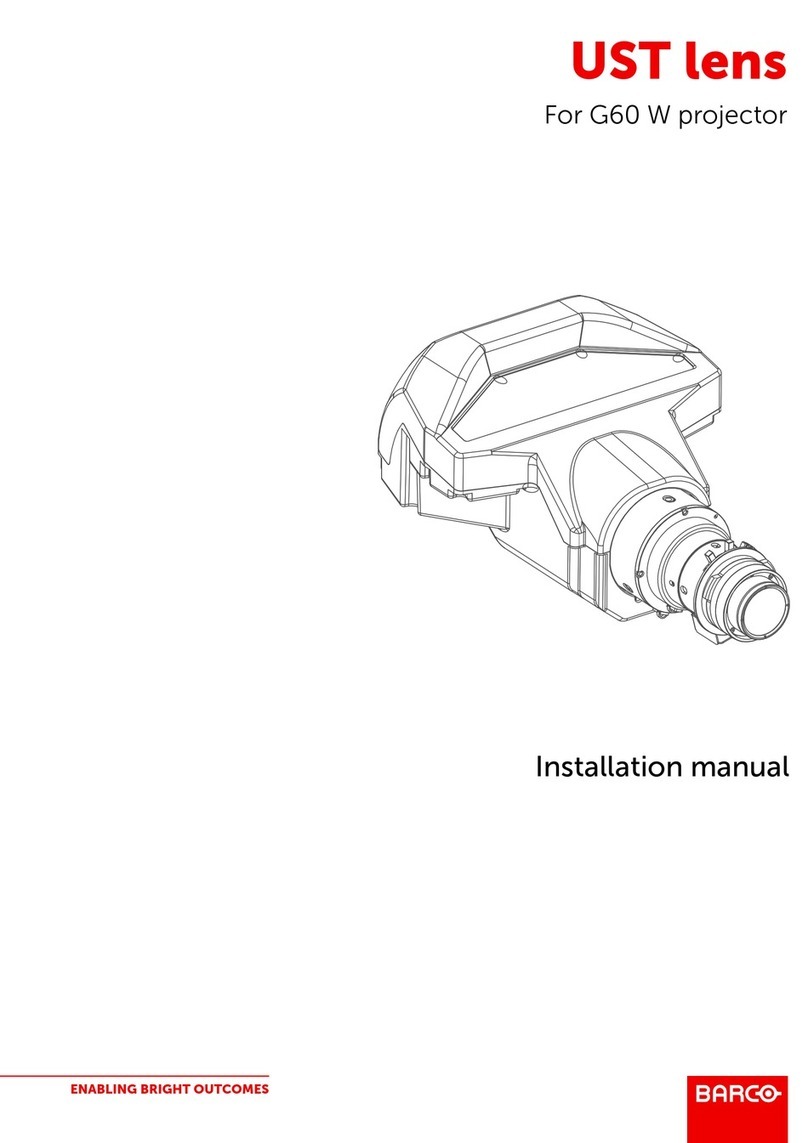
UST lens for F-series

Registered office: Barco NV
President Kennedypark 35, 8500 Kortrijk, Belgium
www.barco.com/en/support
www.barco.com
Barco NV
Beneluxpark 21, 8500 Kortrijk, Belgium
www.barco.com/en/support
www.barco.com

R5912118 /01 UST lens for F-series4
1.1 Preparation of the lens
Overview
This lens can be mounted on 4 different projectors and in different position for each projector. E.g. facing up,
facing to the left or facing to the right. For each position the lens has to be rebuild according the its use and
projector type. The motor housing must be turned to the correct position before the lens is mounted in the
projector.
The following positions for the lens are possible:
•For F40: facing up, to the left and to the right (not indicated on drawing)
Image 1-1
•For F70: facing up and to the left
Image 1-2
Do not use for projection to the left when mounted in a frame.
•For F80: facing up and to the left
General

R5912118 /01 UST lens for F-series6
Image 1-6
Be aware that the position for Up and left for F80 is not the same as for the other projector models.
Required tools
Allen key 2 mm with long shaft (delivered with the kit)
How to prepare the lens for all F-series
1. Place the lens on a table. Turn out the 6 screws (1). Use an Allen key with a long shaft so that you do not
damage the screw head. These screws will not be reused.
Note: Always use the correct tool (delivered with the kit) to avoid damage to the screw heads !
1
Image 1-7
General

R5912118 /01 UST lens for F-series 7
1
Image 1-8
2. Slide the motor housing a few mm to the backside of the lens (2) to disengage focusing gear and motor gear.
Motor unit
Focusing gear Motor gear
Disengage
Slide range: 5mm max
Image 1-9
5mm
2
3
A
Image 1-10
Areference marking
3. Rotate the motor housing until the chosen marker on the housing corresponds with the reference marking on
the lens body (steps of 30°). See if the mounting holes matches the holes in the lens body.
E.g. for an FS40 projector, you want to project to the left, then turn the motor housing until the left marking on
the motor housing corresponds with the reference marking on the lens housing.
General

R5912118 /01 UST lens for F-series8
A B C
D E
Image 1-11
AProject LEFT, for F40 and F70
BProject RIGHT for F90 and F40
CProject UP for F40, F70 and F90
DProject LEFT for F80
EProject UP for F80
4. Slide the motor housing back to the front of the lens to re-engage focusing gear and motor gear.
5. Turn in 6 new Allen screws with glue (screws are delivered with the kit). These screws can be multiple times
reused. The turned out old screws can be thrown away.
Use again a tool with a long shaft (Allen key 2 mm, delivered with the kit).
The lens is ready to be mounted on the projector.
How your image is displayed
Projection to the side for any projector:
A B
Image 1-12
ASide view
BTop view
General

R5912118 /01 UST lens for F-series 9
Up projection for any projector:
C D
Image 1-13
CSide view
DBottom view
Extra preparation for F80
1. Slide the lens adaptor on the lens input until it matches the motor housing (1). Make sure the contacts are on
the left top of the adaptor.
1
2
Image 1-14
2. Secure the adaptor by turning it to the right (bayonet fitting) (2).
General

11
When mounting the lens without the support
When mounting the lens without the support, always use a safety cable as shown in the image.
Overview
•When mounting the lens without the support
•Mounting the UST lens on a F90 projector
•Mounting the UST lens on a F70 projector
•Mounting the UST lens on a F40 projector
•Mounting the UST lens on a F80 projector
R5912118 /01 UST lens for F-series
Mounting the lens 2

R5912118 /01 UST lens for F-series12
2.1 When mounting the lens without the support
When using the safety cable
When mounting the lens in a projector without using the specially designed mounting support for this lens.
How to handle before mounting the lens.
1. Stick 3 to 4 clips on the suface of the lens body (1).
2. Snap the first loop end of the safety cable into one of the clips.
1
3
2
Image 2-1
3. Slide the rest of the cable around the lens. Click the cable into every clip it passes in the loop.
4. Slide the cable through the loop end at the beginning of the cable (2).
5. Install an U-bolt on the lens holder with the open ends oriented outwards (3). Make sure that both a part of the
loop end and the outgoing part of the safety cable are placed in the enclosure.
6. Close the U-bolt and tighten it.
Note: Make sure the safety cable is tightened around the lens before tightening the U-bolt nuts.
7. Place the shackle through the free loop end of the safety cable.
8. Mount the lens in the projector.
9. Secure the safety cable around the truss and secure the shackle by turning the safety ring of the shackle over
the open end.
2.2 Mounting the UST lens on a F90 projector
How to mount
1. Turn the projector on its side or on its top cover.
2. Place the bottom support plate on the bottom plate of the projector. Make sure that both fixation holes match
the holes in the bottom plate.
Mounting the lens

R5912118 /01 UST lens for F-series 13
Image 2-2: Support plate
3. Turn in both M6 screws.
4. Turn the projector back on its feet.
Slide the lens locking system to the left.
Insert the lens. Make sure the electric contact points (C) on the lens match the contact points on the lens
holder.
Image 2-3: Mounting lens
Mounting the lens

R5912118 /01 UST lens for F-series14
C
Image 2-4: Contact points
5. When the lens is on its place, close the lens locking system by moving the handle from the left to the right.
6. Project an image and adjust the shift. See projector’s user manual for more information about shifting the
image.
Note: Shift cannot be adjusted anymore after full installation of the complete kit.
7. Slide plate 2 on both threaded rods and turn a nut on each rod. Do not fasten yet! It must be possible to move
the plate a little bit while mounting the other plates.
Image 2-5: Mount 2nd plate
8. Mount the 3th plate on the 2nd plate. Use the upper mounting holes in the 2nd plate.
Drive in both screws but do not fasten yet.
Mounting the lens

R5912118 /01 UST lens for F-series 15
Image 2-6: Mount 3th plate
9. Place the clamping bracket on the lens so that the fixation holes matches the holes in the support.
Drive in both fixation screws. If necessary, move the 3th plate a little bit until it fully match with the lens.
Fully secure both screws.
Image 2-7: Mount clamp bracket
10. Fully fasten the screws of the 3th plate and the nuts of the 2nd plate so that the support is fully assembled.
The projector is ready for use.
2.3 Mounting the UST lens on a F70 projector
How to mount
1. Turn the projector on its side or on its top cover.
2. Place the bottom support plate on the bottom plate of the projector. Make sure that the fixation holes match
the holes in the bottom plate.
Mounting the lens

R5912118 /01 UST lens for F-series16
M6
M6
M6
M6
M4
M4
Image 2-8: Mount the bottom plate
3. Turn in both M6 screws and the M4 screw.
4. Turn the projector back on its feet.
Slide the lens locking system to the left.
Insert the lens. Make sure the electric contact points (C) on the lens match the contact points on the lens
holder.
Image 2-9: Mount the lens
Mounting the lens

R5912118 /01 UST lens for F-series 17
C
Image 2-10
5. When the lens is on its place, close the lens locking system by moving the handle from the left to the right.
6. Project an image and adjust the shift. See projector’s user manual for more information about lens shift.
Note: Shift cannot be adjusted anymore after full installation of the complete kit.
7. Slide plate 2 on both threaded rods and turn a nut on each rod. Do not fasten yet! It must be possible to move
the plate a little bit while mounting the other plates.
Image 2-11: Mount the 2nd plate
8. Mount the 3th plate on the 2nd plate. Use the upper mounting holes in the 2nd plate.
Drive in both screws but do not fasten yet.
Mounting the lens

R5912118 /01 UST lens for F-series18
Image 2-12: Mount the 3th plate
9. Place the clamping bracket on the lens so that the fixation holes matches the holes in the support.
Drive in both fixation screws. If necessary, move the 3th plate a little bit until it fully match with the lens.
Fully secure both screws.
Image 2-13: Mount clamp bracket
10. Fully fasten the screws of the 3th plate and the nuts of the 2nd plate so that the support is fully assembled.
The projector is ready for use.
2.4 Mounting the UST lens on a F40 projector
How to mount
1. Turn the projector on its side or on its top cover.
2. Place the bottom support plate on the bottom plate of the projector. Make sure that the fixation holes match
the holes in the bottom plate.
Mounting the lens

R5912118 /01 UST lens for F-series 19
Image 2-14: Mount bottom plate
3. Turn in the 3 M6 screws.
4. Turn the projector back on its feet.
Slide the lens locking system to the left.
Insert the lens. Make sure the electric contact points (C) on the lens match the contact points on the lens
holder.
Mounting the lens
Other manuals for UST
1
Table of contents
Other Barco Lens manuals

Barco
Barco QVD (7:1) User manual

Barco
Barco TLD HB 1.6 User manual

Barco
Barco QCLD (1.1 - 1.3:1) IRIS User manual
Barco
Barco UST-Lens User manual

Barco
Barco TLD HB (0.8:1) User manual

Barco
Barco R9829790 User manual

Barco
Barco TLD User manual

Barco
Barco R9849975 User manual

Barco
Barco R9849975 User manual

Barco
Barco UST User manual
Popular Lens manuals by other brands

Olympus
Olympus M. ZUIKO DIGITAL ED 12-200mm f3.5-6.3 instructions

Tokina
Tokina Cinema ATX 11-16mm instruction manual

Sony
Sony LKRL-Z200 Series Product information

HOZAN
HOZAN L-600-12 instruction manual

Fluke
Fluke FLK-TI-LENS/TELE1 instruction sheet

Nikon
Nikon NIKKOR AF-P DX 10-20mm f/4.5-5.6G VR user manual