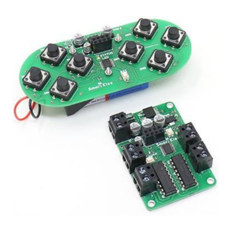
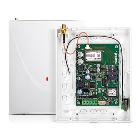
Beckmann Egle MT 20x2 User manual

www.bue.de
Manual
MT 20x2/40x2
EN
Attention! Read this first!
Read through the Instructions manual carefully. The guarantee becomes null and void if damage
or injury results from non-compliance with these instructions. We cannot assume any liability for
consequential damage or injury.

MT 20x2/40x2
Copyright BECKMANN+EGLE GmbH, all rights reserved. Page 2 Internet: www.bue.de
Content
Introduction ....................................................................................................................................... 2
Safety Information ............................................................................................................................. 3
Guarantee ......................................................................................................................................... 3
Description of Functions.................................................................................................................... 4
Set-up ............................................................................................................................................... 5
Connectors........................................................................................................................................ 7
PCB Layout ....................................................................................................................................... 9
Power Supply Options ......................................................................................................................10
Memory Expansion...........................................................................................................................11
Operation .........................................................................................................................................12
MiniTerminal Commands..................................................................................................................13
Maintenance, Disposal .....................................................................................................................18
Problem-Solving ...............................................................................................................................18
Accessories......................................................................................................................................18
Fonttable LCD ..................................................................................................................................19
Technical Specifications...................................................................................................................20
Introduction
Dear Customer,
Thank you for buying the MiniTerminal. Your MiniTerminal is a product which was
manufactured with state-of-the-art technology.
This product conforms to valid European and national safety guidelines. Conformity
has been certified; the relevant documents are in the manufacturer's possession.
To maintain this standard and ensure safe operation, you as user must comply with the
Instructions manual.
Our Internet site at www.bue.de will help you answer Frequently Asked Questions and
provide tips and updated handbooks.
This symbol indicates important instructions which must be followed.
Imprint
These Instructions for Use were published by Beckmann+Egle GmbH, Kernen. All rights reserved. Neither this publication nor any part of it
may be reproduced, stored in a retrieval system, or transmitted in any form or by any means, electronic, mechanical, photocopying,
recording or otherwise, without the publisher's prior consent in writing.
These Instructions for Use are based on the technology used at the time of printing. Changes in technology and equipment are reserved.
Revision history
Date Rev Reason
13.05.02 0/ST complete review

MT 20x2/40x2
Copyright BECKMANN+EGLE GmbH, all rights reserved. Page 3 Internet: www.bue.de
Safety Information
Please observe the following when using the product:
• This MiniTerminal left our factory in perfect technical condition. To preserve this state
and ensure safe operation, the user must observe the safety instructions and
warnings.
o Electronic components and accessories do not belong into child hands.
• Accident prevention regulations issued by the industrial trade associations and
pertaining to the safe use of electrical appliances and equipment on registered
commercial premises must be complied with.
• A responsible person, trained in the use of electrical equipment, must be present
when this product is used in schools, further education classes, DIY and self-help
groups.
• Turn power OFF before making any changes to the hardware-configuration.
• Use in adverse environmental conditions is prohibited.
Such adverse conditions may include:
- areas exposed to moisture or high levels of humidity,
- environments containing dust and combustible gases, vapours or solvents
- during lightning or weather likely to induce strong electrical fields.
• The user is obliged to ascertain whether the product is suitable for the purpose for
which he intends to use it.
• Parts leading high voltage (e.g. inverter for backlight) must be secured against
unintentionally contact.
• Electrostatic sensitive devices – observe precautions for handling.
Guarantee
•
••
•
The guarantee covers the cost-free replacement or repair of faulty parts which can be
proved to have resulted from the use of defective material or errors in production.
Parts subject to normal wear and tear are specifically excluded from this guarantee.
• We cannot accept any responsibility for any damage or injury resulting from the use
of this product.
•
••
•
The customer accepts all costs for delivery and return of goods, and any charges
which may apply in the event of machine failure or modifications to the device
undertaken by us.
•
••
•
Additional claims are excluded.

MT 20x2/40x2
Copyright BECKMANN+EGLE GmbH, all rights reserved. Page 4 Internet: www.bue.de
Description of Functions
LCD character modules are relatively inexpensive and extremely suitable for simple user
operations and status displays. The MiniTerminal simplifies the use of LCD character
modules by providing a link-up to a standard RS232 interface and a range of additional
functions.
• Operation of standard LCD character modules via a serial RS232 interface.
• Standard fixed text memory of 2kB (6kB upgrade available).
• Fixed texts can optionally be accessed via seven TTL lines.
• The character display is independent of fixed text output and can contain a mixture of
both (see the Demo program).
• Mechanically compatible with many LCD displays.
• Connection to a matrix keyboard of up to 32 keys and programmable key codes.
• Power supply is at a standard, stabilised +5 volts.
This product is being continually redeveloped. Changes to the hard- and software, in
particular those relating to the command sequences and position and configuration of
connections and power supply, may be made at any time. Before using this product, please
examine its suitability for the intended use.
Please also visit our homepage at www.bue.de where you can find answers to Frequently
Asked Questions and information on software updates from time to time.
A suitable product is available should you require more complex displays. The “Graphic
Terminal MTGR“ is perfect for graphic LCD displays with a variety of resolutions up to VGA.

MT 20x2/40x2
Copyright BECKMANN+EGLE GmbH, all rights reserved. Page 5 Internet: www.bue.de
Set-up
Assembling the display on the MiniTerminal is easy with the assembly materials provided.
This is illustrated below with a 20x2 display. The procedure is the same for other types
although the position of the plug may vary from the illustration.
A Assembly
1. You will need
• MiniTerminal
• Accessory pack (included with
MiniTerminal)
• Layout diagram
• 20x2 Display
• Soldering iron and solder
• Screwdriver
• Power supply, 5V stabilised
• Interface cable
• PC with TerminalProgramm, e.g.
HyperTerminal or MITAS
software, available separately
MiniTerminal standard accessories
2. Soldering in the connectors
• Solder socket board to display.
Do NOT solder directly to
MiniTerminal !
• Depending on the display in use,
solder the pin connectors to the
matching soldiering position on
the reverse of the PCB
• the pin connectors fit precisely
when both circuit boards are
assembled back to back
• does not need a connecting cable
3. Assembling
• Depending on the display type
being used, some of the
mounting holes cannot be used.
In order to avoid short-circuits
between display ans Terminal put
a suited placeholder between.
• Mount the display with the help of
the spacers, screws and washers
provided (affix these on the
terminal side to avoid short-
circuits on the MiniTerminal).
Readily assembled module
Bushings
Pins here

MT 20x2/40x2
Copyright BECKMANN+EGLE GmbH, all rights reserved. Page 6 Internet: www.bue.de
B Settings
4. Determining power supply
• 5V Jumper J1; J2 closed
(optional power supply see app. section)
5. Determining operating mode
• Set jumper J9 to the desired operating mode
(open=’FixedText’, closed = 'Bus').
Select 'Bus' for the first test: MiniTerminal's 'on' message remains displayed and
contrast can be adjusted properly. In 'FixedText' mode, conversely, the 'on' message
disappears after a short time and the relevant fixed text is displayed, which may still
be empty on delivery, in which case nothing appears.
C Initial operation
6. Initial operation
• Connect the stabilised power supply to the clip connector, make sure that
polarity and voltage is correct. A stabilised 5V is required if a voltage stabilizer
is not used.
• Configure the potentiometer P1 so that the display can be easily read.
You should be able to read the configuration data:
V<Software Version> T<Display Type> B<Baud Rate>
Example (default setting): V 1.6 T4 B0
7. Connecting to a PC
• Using the connecting cable and an extension cable if needed (but not a zero
modem), connect the 10-pole CN6 jack to a serial interface (COM1 or COM2)
on the PC
• Start the terminal program (transfer parameters: 9600/N/8/2, terminal
emulation 'none' or 'TTY'). Now enter a text as it should be displayed on the
MiniTerminal.
8. The MiniTerminal is now ready for operation
Important:
• If a 40x2 display is used, the MiniTerminal must first be configured accordingly;
otherwise the display will not be correct:
o to correctly control a 40x2 display, the command sequence
'ESC &S [11]’ must be entered, where ESC and [11] are entered as
bytes. To do this, press the Alt key – not the ESC key - and type in the
digits '2' and '7' on the numerical keypad for ESC and '11' for [11].
These characters are not displayed on the screen!
• If you are using a voltage stabilizer please read the Power Supply section
• Turn power OFF before making any changes to display configuration

MT 20x2/40x2
Copyright BECKMANN+EGLE GmbH, all rights reserved. Page 7 Internet: www.bue.de
Connectors
The position of each connector can be found on the relevant layout diagram. Make shure to
turn off the device if making changes in wirement. Remember the mode to count the pins on
the different connectors.
KL1 Power supply
Pin Assignment
1GND
2+UB
J1 open : Using a voltage stabilizer
J1 closed : 5V stabilized
CN3 Connector for Matrix Keyboard
Line Allocation Pin No CN3
Column Allocation
Column 0-> 2 1
Column 1-> 4 3
Column 2-> 6 5
Column 3-> 8 7
Column 4-> 10 9 <- Line0
Column 5-> 12 11 <- Line1
Column 6-> 14 13 <- Line2
Column 7-> 16 15 <- Line3
CN4 Connector for Fixed Text / Address Selection
Pin
FT-Mode
J9=1
Description Bus Mode
J9=0
Description
1 FT0 Adr0
2 FT1 Adr1
3 FT2 Adr2
4 FT3 Adr3
5 FT4
6 FT5
7 FT6
Number of fixed text for
output (0 .... 127 binary
encoded)
B..: for FixedText 1, FT1-
FT6 must be set to '0’ and
FT0 to '1’ or open.
8n.c. (not assigned)
9GND
Binary address
encoding,
Address. 0....15
Example: Connection for fixed text query via CN4
FT0
FT1
FT2
FT3
FT4
FT5
FT6
(nc)
GND
CN4 Switch
1 x 1
0 x 2
0 x 4
1 x 8
0 x 16
0 x 32
0 x 64
=> FixedText or Address 9
selected
1
9

MT 20x2/40x2
Copyright BECKMANN+EGLE GmbH, all rights reserved. Page 8 Internet: www.bue.de
CN5 Connector for piezoelectric buzzer (optional)
Pin Assignment
1+
2GND
V16 = BC817 and R18 = 4.7kOhm must be added
This is a switched output (max. 150mA) which is activated by the BEL control
character (07h) for approx. 30ms.
CN6 Connector for Serial Interface
Pin
Assignment
associated pin
Sub-D jack
=PC side
1,2,4,7,8 (not
assigned)
3TXD 2 (=RXD)
5RXD 3 (=TXD)
6RTS 8 (=CTS)
9GND 5 (=GND)
10 +5V -
The plug is positioned so that a 1-to-1 link to a 9-pole sub-D bushing or bracket
connector can be created using a flatband cable.
The +5V on Pin 10 can be used as a power output for further components, although
dissipation should be checked if a voltage stabilizer is used.
CN7 Connector for 20x2/40x2 LCD display
Pin Assignment Pin Assignment
1 GND,0V 9 DB2
2 + 5V 10 DB3
3 VEE (Contrast Voltage) 11 DB4
4 RS (Register Select) 12 DB5
5 R/W (Read/Write) 13 DB6
6 E (Enable Signal) 14 DB7
7 DB0 (Data Bus) 15 (Backlight +UB via R9/R10)
8 DB1 16 (Backlight GND via R5/R6)
Please note: If connector cables for LCDs are used, pull-up resistors must be
positioned on all control and data circuits (Pin4 - Pin14).
Resistors R5 and R9 should be soldered corresponding to the installed backlights.
Dissipation should be taken into account!
Examples
possible layout
Backlight +UB Power
consumption
voltage multiplier
needed (OHM) R5 R9
4.2V approx. 170mA 4.7 4.7 Jumper standard

MT 20x2/40x2
Copyright BECKMANN+EGLE GmbH, all rights reserved. Page 9 Internet: www.bue.de
Jumper
J1 Connection external/internal GND when using a DC/DC converter or 5V
standard supply (default)
J2 connection for direct 5V supply (default)
J3 second CS-signal from controller (see ESC &T command)
Pin description
1-
2CS2
PCB Layout
MT 20x2/40x2
Component side, PCB Rev. 0

MT 20x2/40x2
Copyright BECKMANN+EGLE GmbH, all rights reserved. Page 10 Internet: www.bue.de
Power Supply Options
5V (standard)
• J1 is bridged
• J2 is bridged
• no voltage stabilizer
+9-15V with voltage stabilizer 7805
• J1 is bridged
• J2 is open
• Solder voltage stabilizer, watch
polarity and add:
F1 Fuse Polyswitch 1,1A
V1 Diode ICTE36
C5,C6 Capacitor 100nF
C9 Capacitor 47uF/10V
U7 Voltage
stabilizer
LM7805
Warning: if LCDs with backlight are
used, dissipation of voltage stabilizer
must be checked !
Dissipation of 2W will already occur at
12V operating voltage and 300mA
consumption !
+18-36V with DC/DC-Converter
• J1 is OPEN
(for galvanic separation)
• J1 is bridged
(for shared GND)
• J2 is open
• add:
F1 Fuse Polyswitch 1,1A
V1 Diode ICTE36
C5,C6 Capacitor 100nF
C9 Capacitor 47uF/10V
G1 DC/DC-
converter
TRACO 3-2411
or similar
Pin assignment DC/DC converter
Pin Assignment
1,22,23,24 Vin +
2,3,12,13 Vin -
4-8
17-21
(not available)
9not assigned
10,15,16 Vout -
11,14 Vout +
J2
J1

MT 20x2/40x2
Copyright BECKMANN+EGLE GmbH, all rights reserved. Page 11 Internet: www.bue.de
Memory Expansion
A maximum of 2 EEPROM memory chips (type 24C16) can be added. The following
combinations are allowed:
When adding memory chips check
polarity is correct and whether another
filter capacitor 100nF should be added.
Memory EE1 EE 2 EE 3
2kB occupied (-) (-)
4kB occupied occupied (-)
6kB occupied occupied occupied
EE
3
EE2 EE1

MT 20x2/40x2
Copyright BECKMANN+EGLE GmbH, all rights reserved. Page 12 Internet: www.bue.de
Operation
The terminal is controlled by command sequences delivered via a serial interface or by
calling up pre-programmed fixed texts by contact arrangement.
Data Transfer
Data transfer takes place via the MiniTerminal's RS232 interface.
Standard setting: 9600 Baud / 8 Data bits / No Parity / 2 Stop bits
If 2 Stop bits cannot be applied on the transmitter, 1 Stop bit should ensure full
functionality.
Setting options: 1200, 2400, 4800, 9600 Baud (see Commands)
The serial interface cannot send and receive simultaneously. The MiniTerminal's
RTS signal (or CTS signal on the PC) should be checked when using the keyboard.
Addressing
It's possible to link up to 16 MiniTerminals with a serial interface. In this case the TX
and CTS should NOT be connected (and fixed texts must be programmed before the
devices are connected, see Commands "ESC R").
To enable communication with individual terminals, addresses are assigned on CN4,
pins 1-4. The MiniTerminal recognises all addresses as standard and so no encoding
is necessary for CN4, pins 1-4.
CN4 Function
Pin 1 Addr0
Pin 2 Addr1
Pin 3 Addr2
Pin 4 Addr3
binary encoded,
open connector is
High / 1
J9 close = Bus Mode
open = Auto Fixed Text
Standard
Keyboard
The maximum dimension of the matrix keyboard is 8 columns and 4 lines (32 keys). It
is connected to connector CN3. On pressing a key, the MiniTerminal sends the
keycode to the PC or processor. Because it is not possible to send and receive
simultaneously, the CTS line should be set before the keycode is sent to avoid
collisions.
A short-circuit may occur on the keyboard's µP outport if several keys are pressed at
once. This may lead to malfunctions of the µP. For this reason, a barrier diode
should be added to every key column input (see ill.).
PinNo Line
CN3
9 0
11 1
13 2
15 3
Key
1 - 8 00h – 07h
9 - 16 10h – 17h
17 – 24 20h – 27h
25 – 32 30h – 37h
Column 0 1 2 3 4 5 6 7
PinNo CN3 2 4 6 8 10 12 14 16
if Key 19 is pressed, the
MiniTerminal sends the keycode
22h

MT 20x2/40x2
Copyright BECKMANN+EGLE GmbH, all rights reserved. Page 13 Internet: www.bue.de
MiniTerminal Commands
Abbreviations used
CR Carriage Return/Line Feed 0D (hex) / 13 (decimal)
ESC 1B (hex) / 27 (decimal)
Display
ESC [ (Line) ; (Column) H Set cursor
Line 0.. 3 / Column 0..39 All numbers minus leading zeros !
Example: PRINT #1,CHR$(27);"[";CHR$(2);";" ;CHR$(1);CHR$(9);"H";
sets the cursor in the 20th column of the 3rd line
(Note: 2-digit column numbers also output separately)
ESC & # Clear display / Cursor Home
Example: PRINT #1,CHR$(27);"&#";
ESC & C Cursor on
Example: PRINT #1,CHR$(27);"&C"; switches the cursor on
ESC & D Cursor off
Example: PRINT #1,CHR$(27);"&D"; switches the cursor off
ESC [ K Delete to end of line
Example: PRINT #1,CHR$(27);"[K"; deletes all characters to the end of the current
line
ESC & S nSelect display type
n= 0 (^@) 16 x 1 / 8 x 2
1 (^A) 16 x 2
2 (^B) 16 x 4
3 (^C) 20 x 1
4 (^D) 20 x 2
5 (^E) 20 x 4
6 (^F) 24 x 1
7 (^G) 24 x 2
8 (^H 32 x 1
9 (^I) 32 x 2
10 (^J) 40 x 1
11 (^K) 40 x 2
12 (^L) 40 x 4
Example: PRINT #1,CHR$(27);"&S";CHR$(2); Initialises the MiniTerminal for a 16 x 4 display
This information is stored in EEPROM

MT 20x2/40x2
Copyright BECKMANN+EGLE GmbH, all rights reserved. Page 14 Internet: www.bue.de
Keyboard
ESC & u Byte0 ..... Byte31 Change keyboard layout
The original keycodes are replaced in sequence with the 32 bytes following the "u".
The keycodes, liked the fixed texts, are permanently stored in EEPROM.
Example: PRINT #1,CHR$(27);"&u";
TEXT$ = "abcdefghijklmnopqrstuvwxyz,.;:?" ' new keycode
L = LEN(TEXT$)
FOR I=1 TO L
PRINT #1,MID$(TEXT$,I,1);
R$ = INPUT$(1,#1)
IF R$ <> MID$(TEXT$,I,1) THEN GOTO error ' Error while saving
NEXT I
error:
PRINT "Error while saving"
end:
END
Default settings
Key Keycode (hexadecimal)
1 - 8 00h – 07h
9 - 16 10h – 17h
17 - 24 20h – 27h
25 - 32 30h – 37h
Please note:
The baud rate and code map settings remain in memory even if in the even of power failure. These
settings can only be changed by using the Escape sequences detailed above.
ESC & P n Set keyboard operation mode (from V1.6)
This command sets the keyboard operation mode:
n=0 Polling mode: the code of the last pressed key is only sent when requested and
only when this command has executed. If no key was pressed since the last query,
MiniTerminal outputs the code 255 / FF
n=1 keycode is sent automatically when key is pressed, even if the key is kept pressed.
n=2 ..7 Autorepeat mode: the keycode is sent as long as the key is pressed, ending when
it is released. Various speeds can be set based on n:
2 : very quick to 7: approx. 2-second frequency
On power on, Autorepeat mode, level 2, is activated.
Example:
PRINT #1,CHR$(27);"&P0"; Keyboard in Polling mode and request last keycode
PRINT #1,CHR$(27);"&P5"; Keyboard in Autorepeat mode with approx. 1 second delay
between keycode transmit

MT 20x2/40x2
Copyright BECKMANN+EGLE GmbH, all rights reserved. Page 15 Internet: www.bue.de
Interface
ESC & A address Assign address
ESC & A Z Select all (default value)
Address = 0...15
Example:
Print #1, CHR$(27); "&A";CHR$(1) only MiniTerminal assigned with Address 1
evaluates data
Print #1, CHR$(27); "&AZ"; all connected MiniTerminals evaluate data
(default)
ESC & Bn Set baud rate
This setting is permanently stored in EEPROM
n = 0(9600), 1 (4800), 2 (2400), 3(1200)
Example:
PRINT #1,CHR$(27);"&B";CHR$(2); sets baud rate to 2400 bits per second
.
Font
ESC & L CG Character 8x pattern Redefine existing characters
CG Character addresses 1-8 used.
8 addresses are available for user-defined characters.
Character The character to be redefined. Any character in the font can be entered.
8x Pattern Enter the bit design for the new character. A character comprises a 5x7 matrix. Only
Bit0 - Bit4 of the 7 bytes to be entered are relevant.
The 8th byte is always CHR$(0).
Example program (QBasic) :
´Define interface
OPEN "COM1:9600,N,8,2,cs0,ds0,cd0,rs" AS 1
'Character Pattern
pattern$ = CHR$(4)+CHR$(14)+CHR$(31)+CHR$(4)+CHR$(4)+CHR$(14)+CHR$(17)+CHR$(0)
INPUT "Character to redefine:"; zch$
INPUT "CG RAM Address to be used (1-8) :"; CGAdr%
'ESC sequence for redefinition of character
PRINT #1, CHR$(27) + "&L";
PRINT #1, CHR$(CGAdr% - 1);
ctrl$ = zch$ + pattern$
l = LEN(ctrl$)
IF l <> 0 THEN
FOR n = 1 TO l
PRINT #1, MID$(ctrl$, n, 1);
R$ = INPUT$(1, #1)
IF R$ <> MID$(ctrl$, n, 1) THEN
PRINT "Error while saving": BEEP
EXIT FOR
END IF
NEXT n
END IF
Deleting redefined characters:
Enter a value between CHR$(10) - CHR$(18) (not displayable) for the character to be redefined
(zch$) and the CG RAM address (CGAdr%) to be deleted.
76543210
Bit
=CHR$(4)
=CHR$(14)
=CHR$(31)
=CHR$(4)
=CHR$(4)
=CHR$(14)
=CHR$(17)
=CHR$(0)
Example

MT 20x2/40x2
Copyright BECKMANN+EGLE GmbH, all rights reserved. Page 16 Internet: www.bue.de
Fixed texts
• Fixed texts are numbered from 0 to 127.
• The display is cleared before fixed text is output.
• Fixed texts may contain the special character CR.
ESC W Output fixed texts via serial interface
The MiniTerminal outputs all stored fixed texts in sequence via the serial interface. Each fixed text is
terminated by ‘CHR$(0)’. Transfer is terminated by entering ‘CHR$(0)’ twice (See Memory Format
under 'Load Fixed Text').
Example: PRINT #1,CHR$(27);"W";
ESC R Save fixed texts in EEPROM
The MiniTerminal returns every character after entry. If an error is found during entry (for example,
EEPROM is defect or memory is full), the character is inverted. As it is not possible to transmit and
receive simultaneously, you must wait for the character returned by MiniTerminal to appear before
sending the next one.
Saving the text to memory takes approx. 1 second per 100 characters.
Example: PRINT #1,CHR$(27);"R";
PRINT #1,"T"; 1
st character ("T") of the 1st fixed text
INPUT$(1,#1) wait until the character is returned
....
PRINT #1,CHR$(0); End of the 1st fixed text
PRINT #1,"K"; 1
st character ("K") of the 2nd fixed text
INPUT$(1,#1) wait until the character is returned
....
PRINT #1,CHR$(0); End of the nth fixed text
PRINT #1,CHR$(0); End of entry
Warning: All fixed texts stored in EEPROM are overwritten during transfer.
Recommended methods for changing or extending existing fixed texts:
1. Read existing fixed texts with ‘ESC W’ command and save in file (1 fixed text per line)
2. Edit fixed text with ASCII editor (note format for EEPROM).
3. Read fixed texts from file with ‘ESC R’ command and save in EEPROM
-> The MiniTerminal test program featured in the Software chapter contains these functions.
EEPROM storage format:
´FT0´+Chr$(0)+ ´FT1´+Chr$(0)+ ´FT2´+Chr$(0) ........ ´FTn´+Chr$(0)+Chr$(0)
Festtext ausgeben :

MT 20x2/40x2
Copyright BECKMANN+EGLE GmbH, all rights reserved. Page 17 Internet: www.bue.de
ESC D no Display fixed text no. ('no' from 0 .. 127)
This command overwrites the settings on the CN4 jack.
If the value on connector CN4 is changed, the fixed text associated with it is displayed. This means
that a fixed text is selected either when a number is supplied via the serial interface or the
configuration on CN4 is changed (FT mode).
Example:
PRINT #1,CHR$(27);"D";CHR$(2); The MiniTerminal deletes the display and shows
the 3rd fixed text.
Note: The fixed text commands can be used independently of the value of the 'FT/Bus' pins.
That means that fixed texts can be displayed in both modes (Auto Fixed Text or Bus) via
the serial interface.
Miscellaneous
ESC & T Select Transparent mode
In Transparent mode, the host has direct access to the display controller chip (HD44780 or similar).
This mode should only be used by advanced users !
x0 data Write CMD (Address 0)
x1 data Write Data (Address 1)
x2 Read CMD
x3 Read Data
x4 n Select Display Controller
otherwise Exit Transparent Mode
data Character in Hex
n no. of selected display controller in Hex (0=standard, 1=second controller)
x don't care (the upper 4 bits are insignificant)
Example:
PRINT #1,CHR$(27);"&T"; Enter Transparent Mode
PRINT #1,CHR$(0);CHR$(2); Write 02h in Controller Address 0
PRINT #1,CHR$(255); Exit Transparent Mode
ESC & V Output configuration (from V1.6)
The configuration is output via the serial interface. The format is the same used for the power-on
message and is 10 bytes long:
V<Software Version><space> T<Display Type><space> B<Baud Rate>
Example (default setting): V1.6 T4 B0
See the relevant commands to set display type and baud rate for these setting. You must wait for
confirmation before proceeding with each command !

MT 20x2/40x2
Copyright BECKMANN+EGLE GmbH, all rights reserved. Page 18 Internet: www.bue.de
Maintenance, Disposal
Please note the following carefully:
•
••
•
The guarantee becomes null and void in the event of damage or injury resulting from
failure to comply with the Instruction for Use.
•
••
•
Articles which are no longer needed or are defect must be disposed off according to
relevant legislation.
Problem-Solving
Please check the following if problems occur during initial operation:
• Is the power supply correct? (standard 5V stabilized)
• Is polarity on power supply correct?
• Are all contacts on display connection soldered in place?
• Has the display contrast been set?
• Are interface settings correct? (standard 9600/n/8/1)
Accessories
Free QBASIC program
System requirements:
• RS 232 interface (COM1 or Com2)
• EGA or VGA graphics
• DOS 5.0 or above
• Internet access: the program is only available from our homepage at
www.bue.de.
The program is a test algorithm in Qbasic source code. It offers users an easy way to
get to know and use the MiniTerminal's control functions.
Windows software Mitas
MiniTerminal control software for effortless configuration.
The program offers the user the opportunity to get to know and use the
MiniTerminal's functions. It contains important functions to save and modify fixed
texts and an application to reconfigure the font characters.
The program uses a self-explanatory menu system.
System requirements:
Win 9x or above
Win NT 4.0 or above

MT 20x2/40x2
Copyright BECKMANN+EGLE GmbH, all rights reserved. Page 19 Internet: www.bue.de
Fonttable LCD
Characters which can be displayed on a modern LCD display. Special characters may vary
according to display.

MT 20x2/40x2
Copyright BECKMANN+EGLE GmbH, all rights reserved. Page 20 Internet: www.bue.de
Technical Specifications
MT 8x2 MT 16x1/16x2 MT 16x4/20x4 MT 20x2/40x2
Dimensions
(approx., mm)
58 x 32 80 x 36
84 x 44
87 x 60
98 x 60
116 x 33
Power supply
5V X , approx. 15mA without display
9-15V - X X X
18-36V - - X X
Memory (hrs/max) 2k / 2k 2k / 6k 2k / 6k 2k / 6k
Keyboard connection X X X X
Fixed text upload X X X X
Operating temp. (°C) -10 .. +50
Storage temp. (°C) -20 .. +70
This manual suits for next models
1
Table of contents
