Beehive International B100 User manual
:
maintenance
manual
V'
'
v'
•
M ^ J
INTERNATIONAL.
COMPUTER
TERMINAL
4S10
Amelia
Eanhant
Drive
Box
25BBB
•
Salt
Lake
City,
Utah
B-4125
CS013
355-SGOO
•TWX
S10-925-5271
COMPUTER
TERMINAL
Manual
AUGUST
1B7B
This
Documant
has
b««n
praoarad
by
Baahiva
Madical
Electronics
and
is
furnished
on
the
condition
that
it
will
be
used
by
the
customer
solely
for
the
purpose
of
supporting
tha
op«ratior^,
service
and
maintenance
of
Beehive
Tar-
minals.
Tha
rights
of
the
customer
with
respect
to
this
Document
will
be
governed
by
mutually
acceptable
provisions
Of
tha
contract
with
Beehive Me
dical
Electronics.
This
Documant
shall
not
ba
duplicated
by
the
customer,
nor
be
ralessad,
disclosed
or
used,
in
whole
or
In
part,
for
any
purpose
other
than
stated
herein
without
the
express
written
permission
of
said
Beehive
Medical
Electronics.
BEEHIVE
IIMTERIMATIONAL
070
West
SeOO
South
-Box
25B6S
•
Salt
Lake City.
Utah
0-4125*
tBOD
972-6000
TWX
aiO-0SS-5271
^

fieglAtOt
6100
k/fyyuwo/i.
_-,VtX£y^
\^<i\iX
J1aVs___v^i<S
_,
.....^Ic,
^frutrttUr
^WAejl
W
.Arvji^^
Set.
XAfLUt
li
di
OfCUiT.
IV
fO-VVt
t"?
ftlgvtu'l'
yorl~
o|-
j)
Lwi
.W^_
U)V«it-U
Corner
<^leol-e(l.
CLU
|L.-
£iw^
M
f(«
A
CTI-ISl'^
4o
CUi\o
C«
y>iu
10
ilTfps)
M
C^>ip
C8
ip^'vi
<
CL
\*^U.
rUtjg
Dl2,
pi^
10
-tn
TW.
/KAK
CL(^
HouJ
LovI^^^
^
iitxw&l
/ttfc
^
iW.
C:lpc^.._
Co^ls___jW^_..___j/^X.i.,A„_iau!i_^
-vAvi
Tt\P.
QUJcxl'i
^ (V-r
16
COvYyp
«cl
^5
-ElcwO
bi^
Aa>^
OU
,
loefpH
•

Section
4-1
4-2
4-3
5-1
5-2
5-3
5-4
5-5
6-1
6-2
A.
Table
5-1
Figure
4-1
4-2
4-3
4-4
4-5
4-6
4-7
5-1
5-2
5-3
B100
Maintenance
Manual
TABLE
OF
CONTENTS
SECTION
IV
-
THEORY
OF
OPERATION
Introduction
General
Function
Description
Detailed
Functional
Description
SECTION
V -
MAINTENANCE
Introduction
Preventive
Maintenance
Corrective
Maintenance
Monitor
Adjustment
Disassembly
Procedure
SECTION
VI
-
SCHEMATICS
8100
Board
Assembly
Drawing
8100
Schematics
APPENDIX
Monitor
-
General
Information
TABLES
Troubleshooting
Flow
Diagrams
FIGURES
Basic
Block
Diagram
Basic
Functional
Flow
Diagram
Basic
Functional
Flow
Diagram
Power
Supply
Block Diagram
Character
Dot
Matrix
Timing
Diagram
Timing
Diagram
Echoplex
Test
Connector
Monitor
Adjustments
Assembly Drawing
8100
Page
4-1
4-1
4-6
5-1
5-1
5-1
5-17
5-18
6-1
6-2
thru
6-17
Page
5-3-5-15
Page
4-2
4-3
4-4
4-5
4-8
4-9
4-10
5-2
5-16
5-18

SECTION
IV
Theory
of
Operation
4.1
INTRODUCTION
This
section
contains
the
theory
of
operation
for
the
BEEHIVE
B100
Terminal.
This
discussion
is
presented as a functional description
at
adetailed
block diagram level referencing
appropriate
func
tional
blocks
on
the
diagrams.
4.2
GENERAL
FUNCTIONAL
DESCRIPTION
The
8100
consists
of
four
basic
functional
compo
nents, Power Supply, Monitor, Keyboard
and
iVIain
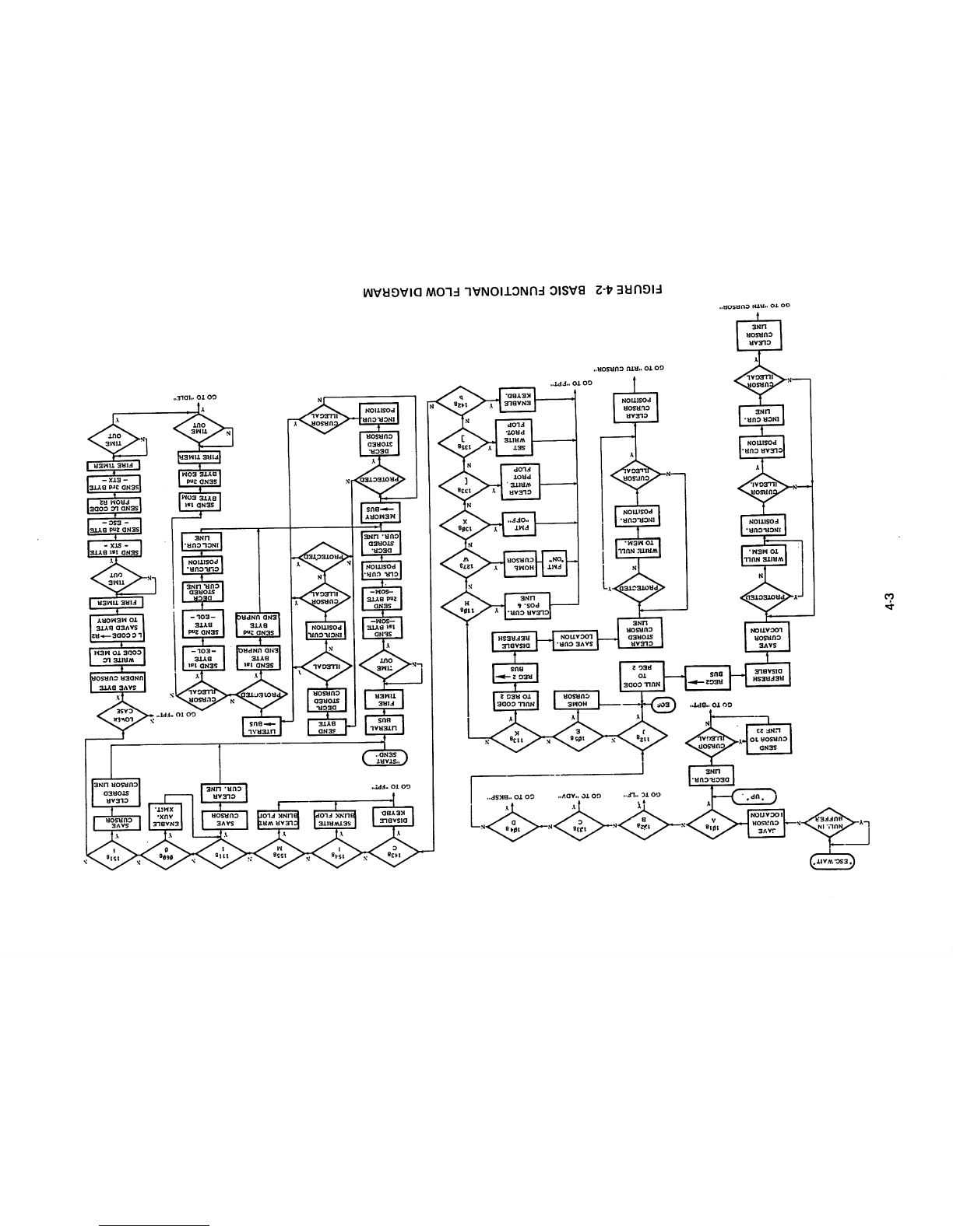
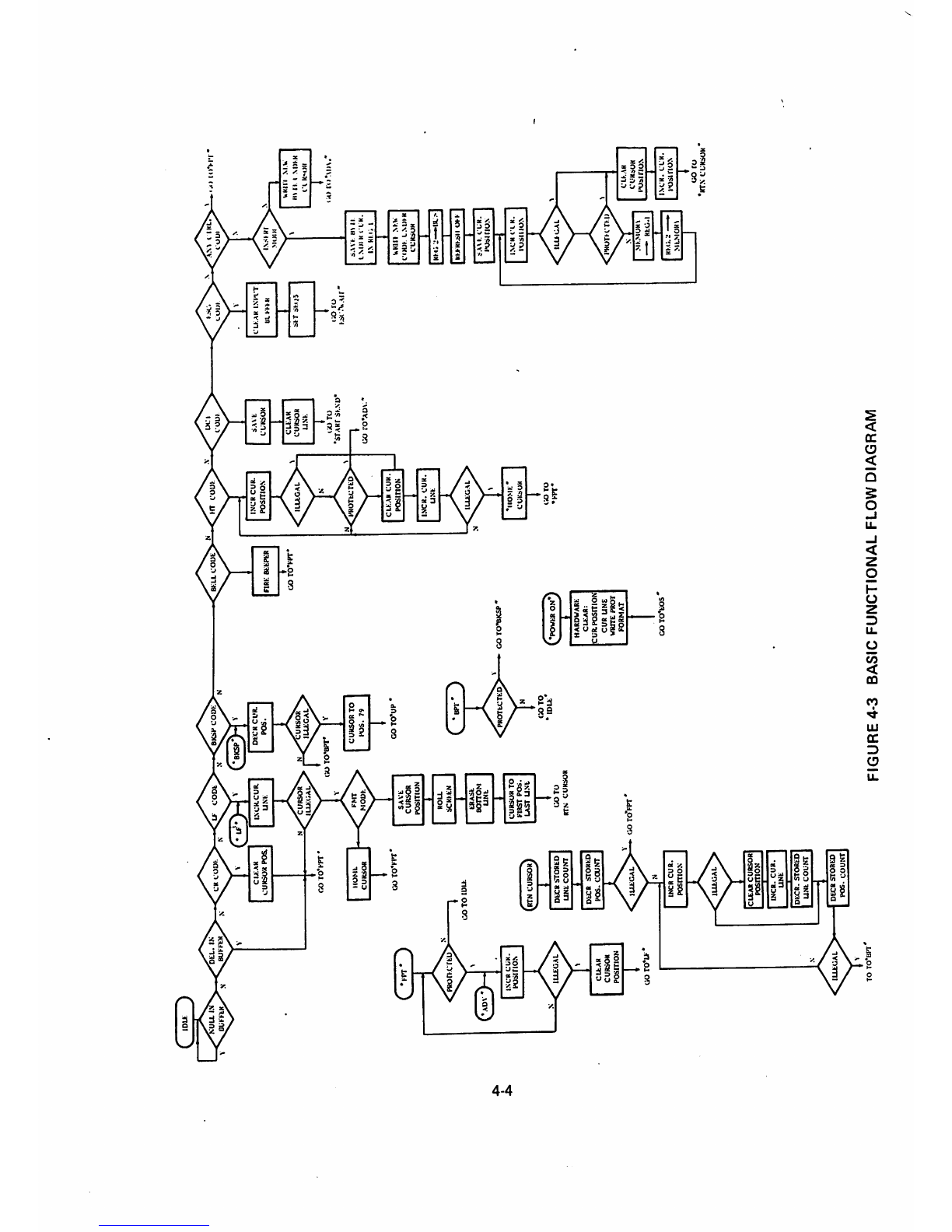
Logic Board. Figure 4-3 shows the basic
functional flow diagram of the terminal. These
functions
are briefly described in
the
following
paragraphs.
4.2.1
Power
Supply
The PowerSupply provides the required,
regula
ted DC voltages
to
the
terminal. This assembly
will
operate
on
100,
115,
200
or
230
VAC
power
(selectable
at
the
factory).
4.2.2
Monitor
The Monitor Assembly includes a 12 inch (30.5
cm), diagonally measured,
CRT
and its
support
ing solid-state circuitry. The Monitor is controlled
by the vertical and horizontal synchronization sig
nals, and the video signals generated on
the
logic
board.
Afull
screen
of
information
consists
of
12
4-1
lines
of
80
characters
~ a
two
raster
scan
between
lines - or the optional feature of 24 lines of 80
characters each. Brightness and contrast adjust
ments are provided by external
potentiometers
located on
the
rear panel, (see Figure 2-2, Section
II). Other monitor adjustments are discussed in
Section
V
and
in
Appendix
A.
4.2.3
Keyboard
The keyboard isthe input
device
used by the opera
tor
to
communicate
with
the
terminal.
The
key
board
contains
the
switches
and
supporting
circuitry
to generatethe appropriate control
signals
and
ASCII codes utilized in
the
B100 terminal.
The
key
board conforms to the proposed ANSI keyboard
standard for data keys,
but
has been expanded to
facilitate
the
capabilities of
the
B100.
4.2.4
Logic
Board
The
Logic
Board
containsthe
major
functionand
control
circuits
in
the
B100
terminal.
It also
holds
all
of
the
DC
voltage
regulators
to
power
the unit. The basic operations accomplished by
the
main
logic
boardare: Generation of data and
control
signals
for the monitor, interactionwith
the keyboard, control of the data sent between
the B100 and any external device, and generation
of
the
basic timing signals essential for
the
opera
tion
of
the
terminal.

ro
MAIN
POHT
CONKIC.
SELECTION
AUX
POHT
CONFIO
SELECTION
PORT
SELECTION
CIRCUIT
UART
RECEIVER
DATA
INPUT
BUFFER
OPERATION
SEQUENCE
INS
MODE
ILLEGAL
PROTECT
FORMAT
HUSY
MODE
ONFI
CRVSTAL
OSCILLATOR
DATA
UART
TRANSMITTER
MODE
DOT
POSITION
^ 7
DPC
BAUD
CLOCK
SELECTION
ROTARY
CHAK
POSITION
96
CPC
BAUD
CLOCK
CKT.
AUX
CLK
MAIN
CLK
f
SET/CLR
CHAR
HEIGHT
. 9
CilC
)
CURSOR
POS
<
CURSOR
LINE
ROLL
WRITE
BUNK
WRITE
PROT.
f
CURSOR
POS
BUSY
DATA
BEADY
0
SEQUENCE
COUNTER
I
SEQUENCE
VIDEO
CURSOR
GENERATION
CIRCUIT
CURSOR >
CURL
CURSOR
UNE
REC.
BCURL
buffered
CURSOR
LINE
OPERATION
REGISTER
CURSOR
LINE
ROLL
COUNTER
OPERATION
CIIAH
LINE
-
26
CLC
XIEMOHY
ADDRESS
MANIPULATION
]<J20 \ 1
lilT
HLINK
1920
X I
BIT
PROTECT
1920
\ 7
BITS
data
refresh
MEMORY
CURP
CURSOR
POSITION
REG.
protect
CURSOR
POSITION
BCURF
BUFFERED
CURSOR
POSITION
ROLL
FIGURE
4-1
BASIC
BLOCK
DIAGRAM
SYNC
viEN.
COX'I'.
>lii
iiiin
i.ii
III.IXK
LOW
Vll>i:
l>l<l\
Kl(
ciHCin
VIDEO
CURSOR
•OFF
SCREEN
CIRCUIT
f d RSOH
VIDEO
SHIf'T
HEUISTEII
CHARACTER
GENERATOR
LOWER
CASE
UPPER
CASE
INSERT/UELETI:;
CIRCUIT
ILLEGAL
KEYIIOARO
CONTROL
LOGIC
V
lll(l\
I.
M
liKU
L
VlliLO
M>'M
I. ;
KROV.
KEYItOAItU
ESCWAIT
UL!.
IN
UFFEi
CO
JAVE
CU.-UOH
lOCAflON
C-lJ
CURSOR
10
UNF
23
SAVE
CURSOR
LOCATION
WRITE
NULL
TO
MEM.
1NCR.CUR.
POSITION
URSOR
ILLEGAL
CLEAR
CUR
POSITION
\
INCR
CUR
UNE
URSO
illegal
CLEAR
CURSOR
DECR.CUR
UNE
cuRSon
liSXiA
GO
TO
"BPT-
GO TO "RTN CURSOR"
GO
TC
"LF"
NULL
CODE
TO
REG
2
CLEAR
STORED
CURSOR
UNE
PROTECTE
WRITE
NULL
TO
MEM.
INCR.CUR.
POSITION
cunsoR
CLEAR
CfRSOR
POSITION
GO
TC
"ADV
HOME
CURSOR
SAVE
CUR.
LOCATION
GO TO
"FPT"
GO TO "RTU
CURSOR
CO
TO
"BKSF
NULL
CODE
TO
REG
a
I
REG
2
BUS
CLEAR
CUR.
POS.
(•
UNE
HOME
CURSOR
CLEAR
WRITE
,
PROT
FLOP
SET
WRITE
PROT
FLOP
ENABLE
KEYBD.
DISABLE
KEYBD.
GO
TO
"FPT"
START
SEND-
UTERAL
BUS
FIRE
TIMER
TIME
SEND
1st
BYTE
SEND
2nd
BYTE
-SOM-
l
CLR.
CUH.
POSITION
I
DECR.
STORED
CUR.
UNE
MEMORY
BUS
DECR.
STORED
CURSOR
I
INCR.
CUR
POSITION
FIGURE 4-2
BASIC
FUNCTIONAL
FLOW
DIAGRAM
SETWRITE
BUNK
FLO
DECR.
STORED
CURSOR
ILLEGAL
INCaCUR.
POSITION
URSOR
ILLEGAL
CURSOH^
V
ILLEGA
LEAR
WR
LINK
FLO
I
UTERAL
BUS
ROlErTE
SEND
1st
BYTE
END
UNPRQI
SEND
2nd
BYTE
END
UNPRa
SAVE
CURSOR
CLEAR
CUR.
UNE
ENABLE
AUX
XMiT.
CO
TO
"FPT
CURSOR
SEND
lat
BYTE
-EOL-
l
SEND
2nd
BYTE
-EOL-
CUR.
LINE
I
CLR.CUR.
POSITION
I
INCLCUR.
UNE
SEND
1st
byte
EOM
i
SEND
2nd
BYTE
EOM
FIRE
TIME
TIME
GO
TO
"IDLE
SAVE
CURSOR
CLEAR
STORED
CURSOR
UNE
LOVtK
CASE
SAVE
BYTE
UNDER
CURSORI
I
WHITE
VC
CODE
TO
MEM
!
LCCODE—•R2
SAVED
BYTE
TO
MEMORY
I
FIRE
TIMER
TIME
OUT
SEND
1st
BYTE
-
STX
-
SEND
2nd
BYTE
-
ESC-
SEND
LC
CODE
FROM
B2
I
SEND
3rd
BYTE
-ETX-
I
FIRE
TIMER
j
TIME
OUT
4^
( )
NUU
j:
Dt^L.
IN
V s
^BUKI-tK
C
''"iJ
PROrVCTKU
ISCR
CUK.
POSITIO.S
ILUGAL
CUAR
CURSOR
POSITION
GOTO^U*
ILUGAL
TO
TO*Bn
'
CK
COOK
cu:ah
CURSOR
POSL
GO
T0>-PT
•
HOML
CURSOR
GO rO^KPT
GO
TO
lUU
^TN
cursor)
DECR
STORED
LINE
COUNT
DECR
STORED
POS.
COUNT
ILLEGAL
INCR
CUR.
POSITION
ILUGAL
LEAR
CURSOR
posmoN
INCH.
CUR.
UNE
decr.
stored
UNE
coura
DECR
STORED
POS.
COUNT
U'
CODl
l\ck.cur.
UN^
CURSOR
ILLKGAL
FMT
MODK
SAVE
CURSOR
POSITION
ROU
SCRKEN
ERASL
OOTTOM
UNL
CURSOR
TO
KlftST
POS.
LAST
UNE
GOTO
ITTN
CURSOR
GO
TO'FPT
*
eKSH
COOK
*BKSP
Dt:CH
CUR.
POS.
:URSOR
ILUGAL
CO
TOW
CURSOR
TO
POS.
79
GO TO*UP •
PROTECTED
<;o
TO
lOU
GO TO'BICSP •
HARDWARE
CUAR:
CURPOSmOA
CUR
UN£
WRITE
PROT
FORMAT
GOTO^EOS
UXLCOUt
HRK
KbPCR
GO
TOW
m
coD^
INCR
CUR.
POSmON
ILUGAL
PROTkCTED
CLKAR
CUR.
POSITION
INCR.
CUR.
UNK
ILUGAL
IIO.MK*
CUKs^OM
CiOTO
ix:i
com
SWi.
CLKSOX
CUAR
CURSOR
UNK
\
IXJ
TO
•STARr
SKND
GO
ro*AD\.
FIGURE
4-3
BASIC
FUNCTIONAL
FLOW
DIAGRAM
CLKAR
INI'l'T
UL
VhkM
SKT
SK05
i;0
l O
KSl-.*V»Air*
(
ikl:
cuui
INSIKf
S.\\>
m 11
LMIl
K
flR.
IN
Kli«
\
URin
NKV
CCMJK
LMJI-N
CCKSUH
irh>Kf^ll
Ot-K
I
ja\k
cur.
posi
rioN
I.NCR
CIR.
PUSH
ION
ILLEGAL
PROTKTKIJ
MKMUM\
REG.
KKG.;:
MEMOR\
UKItl
M.k
I K I
M)KR
I'l
KM)tr
U>
CLK.AH
CURdUK
iVainON
I
INCR.
CLH
POSITION
UO
ru
•irrx
CURSOR

4^
I
CJ1
115/230
vAC
INPUT
TRANSFORMER
BLOCK
RECTIFIER
RECTIFIER
RECTIFIER
H
M
FIGURE
4-4
POWER
SUPPLY
BLOCK
DIAGRAM
+5
V
REGULATOR
+15
REGULATOR
+12
REGULATOR
-12
V
REGULATOR
+5
vDC
>
>
+15vDC
>
+12vDC
j-12vDC
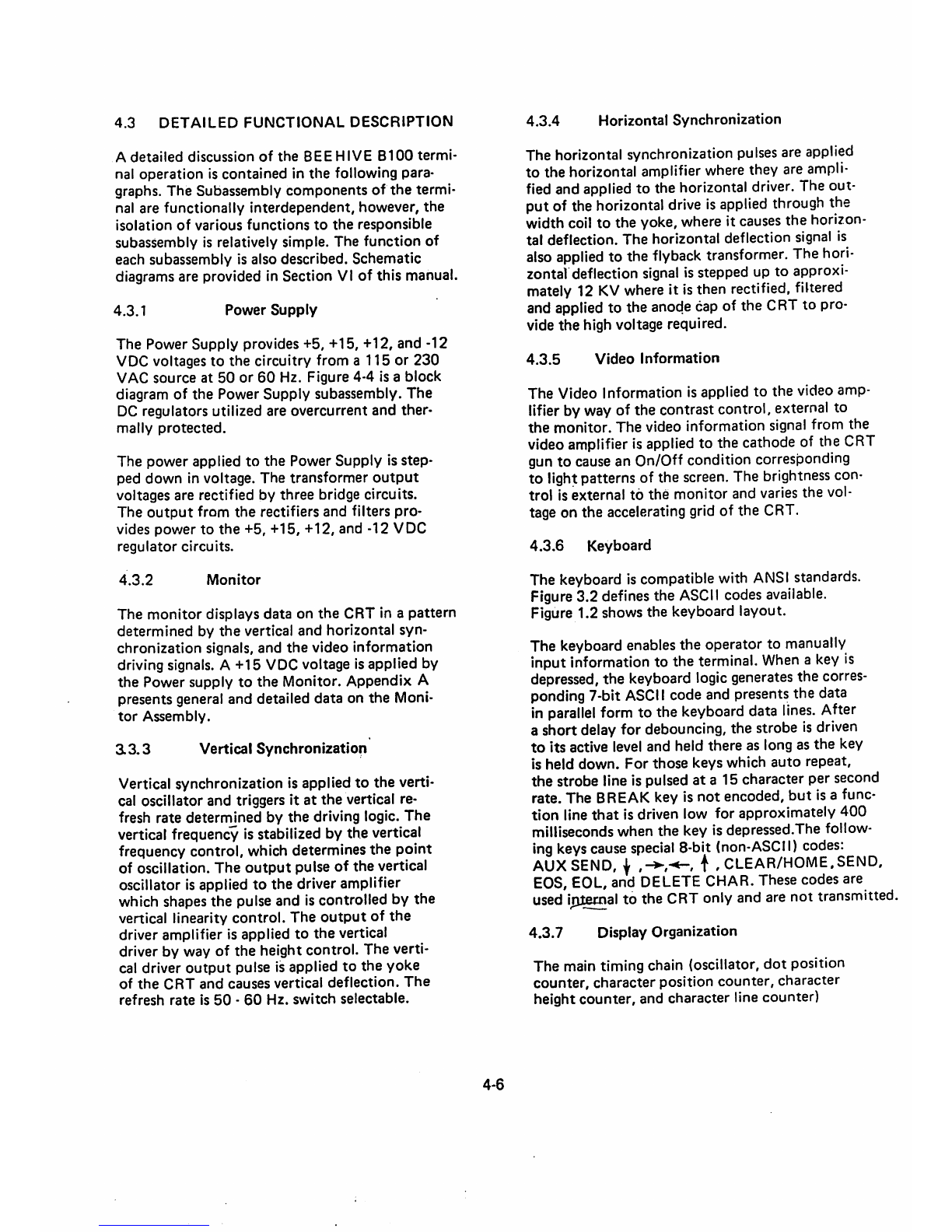
4.3
DETAILED
FUNCTIONAL
DESCRIPTION
A
detailed
discussion
of
the
BEE
HIVE
B100
termi
nal
operation
is
contained
in
the
following
para
graphs. The Subassembly components of
the
termi
nal are functionally
interdependent,
however,
the
isolation
of
various
functions
to
the
responsible
subassembly is relatively simple. The function of
each subassembly is also described.
Schematic
diagrams are provided in Section VI of this manual.
4.3.1
Power
Supply
The
Power
Supply
provides +5, +15, +12,
and
-12
VDC voltages
to
the
circuitry from a
115
or
230
VAC
source
at
50
or
60
Hz. Figure 4-4 is a
block
diagram of
the
Power
Supply
subassembly.
The
DC regulators utilized are overcurrent
and
ther
mally
protected.
The
power
applied
to
the
Power
Supply
is
step
ped
down
in voltage.
The
transformer
output
voltages are rectified by
three
bridge circuits.
The
output
from
the
rectifiers and filters
pro
vides
power
to
the
+5, +15, +12, and -12 VDC
regulator
circuits.
4.3.2
Monitor
The
monitor
displays
data
on
the
CRT in a
pattern
determined
by
the
vertical
and
horizontal syn
chronization
signals, and
the
video
information
driving signals. A +15 VDC voltage is applied by
the Power supply to the Monitor. Appendix A
presents general and detailed data on the Moni
tor
Assembly.
a3.3
Vertical
Synchronization
Vertical synchronization is applied to the verti
cal oscillator and triggers it
at
the
vertical re
fresh rate deternmned by
the
driving logic.
The
vertical frequency is stabilized by the vertical
frequency control, which determines the point
of oscillation. The
output
pulse of the vertical
oscillator is applied to the driver amplifier
which shapes the pulse and is controlled by the
vertical linearity control. The
output
of
the
driver amplifier is applied to
the
vertical
driver by way of the height control. The verti
cal driver
output
pulse is applied to the yoke
of
the
CRT
and
causes
vertical
deflection.
The
refresh
rate
is
50
-
60
Hz.
switch
selectable.
4-6
4.3.4
Horizontal
Synchronization
The horizontal synchronization
pulses
are applied
to the horizontal amplifierwherethey are
ampli
fied and applied to the horizontal driver. The out
put of the horizontal
drive
is
applied
through
the
width coil to the yoke, where it causesthe horizon
tal deflection. The horizontal deflection signal is
also
applied
to the
flyback
transformer.
The
hori
zontaldeflection
signal
isstepped up to approxi
mately
12
KV
where
it isthen rectified, filtered
and applied to the anode cap of the CRT to pro
vide
the
high voltage required.
4.3.5
Video
Information
The
Video Information is applied
to
the
video
amp
lifierby way of the contrast control, external to
the
monitor.
The
video information signal from
the
videoamplifier isapplied to the cathode of the CRT
gun to causean On/Off condition corresponding
to light patterns of the screen. The brightness con
trol is external to the
monitor
and varies the vol
tage on the accelerating grid of the CRT.
4.3.6
Keyboard
The keyboardiscompatiblewith
ANSI
standards.
Figure3.2 defines the
ASCII
codes available.
Figure 1.2 shows the keyboard layout.
The keyboard enables the operator to manually
input information to the terminal.
When
a
key
is
depressed, the keyboard logicgenerates the corres
ponding7-bit
ASCII
code and presents the data
in
parallel
form
to the
keyboard
data
lines.
After
a short delayfor debouncing, the strobe is
driven
to
its active level and held
there
as long as
the
key
is
held
down.
For
those
keys
which
auto
repeat,
the strobe lineis
pulsed
at a 15character per
second
rate. The BREAKkey is not encoded,
but
is a func
tion
line
that
is driven low for approximately
400
milliseconds when the key is depressed.The follow
ingkeyscause
special
8-bit
(non-ASCII)
codes:
AUXSEND,
1 t ,
CLEAR/HOME,SEND,
EOS,
EOL,
and
DELETE
CHAR.
Thesecodesare
used
iplecnal
to
the
CRT
only
and
are
not
transmitted.
4.3.7
Display Organization
The main timing chain (oscillator,
dot
position
counter,
character
position
counter,
character
height counter, and character line counter)

defines the configuration of
the
display on
the
CRT.
There
are
30
lines, 6
of
which
are
used
for
vertical
retrace
and
24
of
which are used
to
display
charac
ters
.
The
30
lines
are
composed
of
nine
scans
each.
Each scan being
composed
of
96
character
times,
80
for
display
and
16
for
horizontal
retrace.
Each
character
block
is
composed
of
7 x 9
dot
matrix
field
which
contains
a 5 x 7
character
matrix
for
the
displayed
character.
Oscillator
The
oscillator is crystal controlled with
a
frequency
of
10.8864
MHz.
Two
74H04's
are
connected
in series by a lOOpf
capacitor.
Each
74H04
has
a 1
Kohm
feedback
resistor
around
it.
A
10.8864
MHz
crystal
is
connected
from
the
input of the first
74H04
to
the
output
of
the
second.
The
output
of
the
oscillator is buffered,
inverted
and
fed
to
the
Dot
Position
Counter.
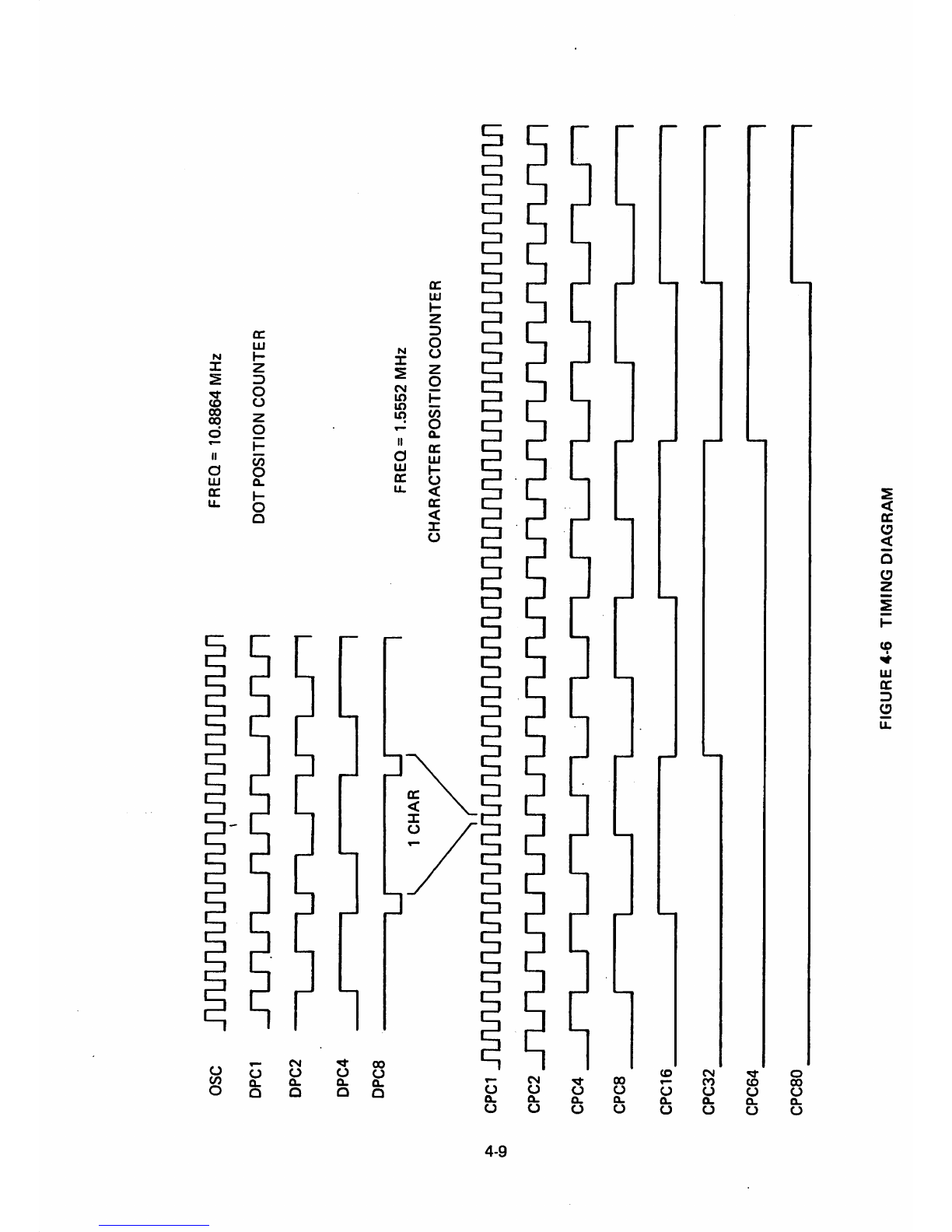
Dot
Position
Counter
This divide-by-seven
coun
ter
defines each
of
the
seven
dots
required
to
compose
one
character.
The
outputs
of
this
four
stage
counter
are
labeled
DPC1,
DPC2, DPC4,
and
DPC8.
The
Counter
actually
presets
to
a
count
of
10,
counts
up
through
the
overflow
point
at
15
to
a
count
of
zero,
and
presets
then
back
to
a
count
of
10.
The
Dot
Position
coun
ter
output,
DPC8,
drives
the
Character
Position
Counter.
Character
Position
Counter
The
Character
Position
Counter
is
composed
of
two
binary-
type
counters
that
define
96
character
times,
each being seven
dots
wide.
The
output
of
the
Character
Position
Counter
drives
the
Charac
ter
Height
Counter.
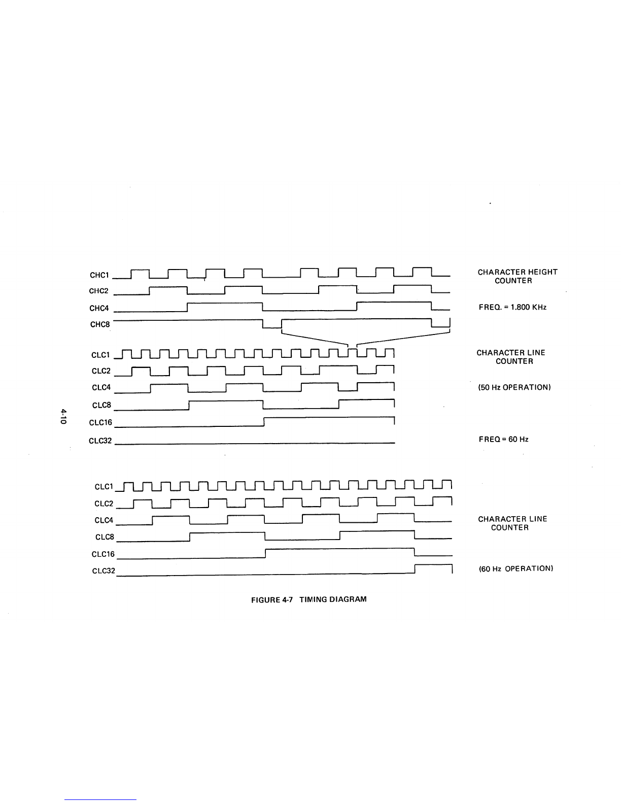
Character Height
Counter
The
Character Height
Counter
is a
standard
counter
that
defines
9
scans
of
96
characters
each,
with
each
charac
ter
being seven-dots wide.
The
output
of
the
Character
Height
Counter
drives
the
Character
Line
Counter.
Character
Line
Counter
The
Character
Line
Counter
is a
binary
counter
that
starts
at
a
count
of
zero
and
counts
to
a
maximum
of
29
for
a
total
of
30
character
lines.
The
final
out
put
of
this
counter
runs
at
the
vertical
refresh
rate.
Horizontal
and
Vertical
Drive
The
Horizontal
4-7
Drive
is
started
when
the
Character
Position
Coun
ter
leaves
the
video
area
of
the
scan
and
is
active
for
the
following
40
character
times.
The
high
active
output
of
this
flip-flop
is
sent
to
the
moni
tor
on
pin
9
of
connector
J1.
The
vertical drive is
generated
during
the
time
that
the
Character
Line
Counter
is
decoding
26.
4.3.8
Cursor
Location
Counter
The
Cursor
Location
Counter
identifies
the
loca
tion
of
the
cursor.
This
is a
count
made
from
the
Cursor
Line
Counter,
called
CURL,
and
the
Cur
sor
Position
Counter^
called
CURP.
These
two
counters,
in
conjunction
with
the
ROLL
counter,
are
used
to
address
the
memory
to
determine
the
entry
point
of
the
next
character.
The
cursor
loca
tion
counters
are
compared
with
the
next
character.
The
cursor
location
counters
are
compared
with
the
Character
Position
Counter
and
the
Character
Line
Counter
to
generate
the
signal
called
CNTR
CURSOR.
This
signal is
used
to
generate
the
cur
sor
displayed
on
the
CRT.
Also
associated
with
the
cursor
location
counters
is
the
appropriate
circuitry
to
move
the
cursor
up,
down,
right,
left,
home,etc.
A
LINE
FEED
code
causes
the
Cursor
Line
Counter
to
increment
by
one.
A
CARRIAGE
RETURN
code
clears
the
Cursor
Position
Counter.
With
the
terminal
operating
in
FORMAT
MODE,
when
the
cursor
is
incremented
off
the
bottom
line,
the
cursor
automatically
wraps
around
to
the
top
of
the
display,
i.e.,
the
Cursor
Line
Counter
is
reset
to
zero.
However,
if
the
terminal
is
not
in
FORMAT
MODE,
the
display
scrolls
whenever
the
cursor
increments
from
a
count
of
23.
Ascroll is
initiated
by
any
of
3
functions
if
act
ivated
when
the
cursor
is
on
the
last
line
of
the
display
and
the
terminal
is
not
in
FORMAT
MODE:
a.
LINE
FEED
or
CTRL
J
b.
CURSOR
DOWNorESCB
c. If
the
cursor
is
on
the
last
position
of
the
last
line.
1.
Cursor
right
2.
Any
displayable
character
3.
Space

SCAN
0
CHARACTER
DISPLAY
SCAN
8
DOT
0
BLANK
f
♦o
o
o •
o •
o •
o •
o •
o •
•o
o
♦o
CHARACTER
DISPLAY
A.
o o o
o o o
ooo
o o o
• • •
o o o
o o o
o o o
o o o
DOT
«
BLANK
DOT
0
BLANK
o o
• o
• o
• o
• o
• o
• o
• o
o o
• o
o o
• o
o o
o o
o o
o o
o o
o o
o o
o o
(—
o o
o •
o •
o •
o •
o •
o •
o •
o o
o o
o o
o •
o •
o •
o •
o •
o •
o •
o o
o o
SCAN
9
FOR
CURSOR
SCAN
0
♦o
o o o o
CHARACTER
DISPLAY
SCAN
8
O •
o •
o •
o •
o •
o •
o •
>o
o
SCAN
9 O
FOR
CURSOR
o o o
o o o
• • •
o o o
o o o
o o o
o o o
ooo
FIGURE
4-5
CHARACTER
DOT
MATRIX
4-8
CHARACTER
DISPLAY
A.
o o o
• • •
o o o
o o o
• • •
o o o
o o o
o o o
o o o
o o o
o o o
o o o
o o o
o o o
• • •
o o o
ooo
o o o
o o o
o o o
DOT
6
BLANK
—\
o o
• o
o o
o o
o o
o o
o o
o o
o o
o o
o o
• o
• o
• o
• o
• o
• o
• o
o o
o o
cb
osc
DPC1
DPC2
DPC4
DPC8
j"ijajn_rLJ"ijn
nrui
—I
r-Lj—^
ru—^^—I
u1
CHAR
FREQ=
10.8864
MHz
DOT
POSITION
COUNTER
FREQ=
1.5552
MHz
CHARACTER
POSITION
COUNTER
CPC1
jTjmjTJumrmnjTJijmJiJinjinLriri^^
CPC2
CPC4
_
CPC8
CPC16
CPC32
CPC64
CPC80
j—^^—L_rn_r
FIGURE
4-6
TIMING
DIAGRAM
O
CHCl
CHC2
CHC4
CHC8
j—M—^
r
CLC2_|
t_J
L_l
l_J
L_J
L I
I—T"
CLC4
I I I 1 I I I
CLCB
CLC16
CLC32
cLci_n_in
CLC2
CLC4
CLC8
CLC16
CLC32
I
LJl
n_rLJ"iTTJ~m
1 r
FIGURE
4-7
TIMING
DIAGRAM
CHARACTER
HEIGHT
COUNTER
FREQ.
=
1.800
KHz
CHARACTER
LINE
COUNTER
(50
Hz
OPERATION)
FREQ
=
60
Hz
CHARACTER
LINE
COUNTER
(60
Hz
OPERATION)

4.3.9
Memory
The page
memory
is actually a
2048
byte
memory.
Each
byte
consists
of
9
bits:
7
for
data,
one
for
protect,
and
one
for
blink.
Of
these
2048
bytes,
1920
are displayable.
The
program
does
not
have
the capability of displaying or writing Into
the
remaining
128.
In
order
to
write
data
into
the
page
memory
from
the
receiver,
the
memory
address
is
muxed
over
to
the
cursor
location
registers
and
the
signal WRITE is generated.
The
UART Is
then
reset and is capable of receiving
the
next
character.
The
page
memory
output
is sent to
the
character
generator
input
buffer
at
the
proper
time
to
generate
the
displayable
characters.
The
program has
the
capability of
shutting down the screen refresh for any given
operation to increase
the
program operating
time.
4.3.10
Character
Generator
The Character Generator is a read-only memory
(ROM)
that
is addressed by the character (in
ASCII).
The
scan configuration
and
the
charac
ter
indicates
the
pattern
desired
on
that
scan,
-ive-bit
dot
patterns
are generated which
form
portion
of
acharacter.
The
output
of
the
character generator is applied
to
the
parallel-
to-serial video
shift
register.
4.3.11
Video
Shift
Register
The paraliel-to-serial Video Shift Register is ^
loaded with data by
the
low-active signal, DPC8,
and is clocked by
the
main oscillator
output.
The
dots
are
shifted
out,
mixed
with
cursor
Informa
tion, and blanking signals, and applied to
the
monitor
through
the
CONTRAST
control
as
video
information^
4.3.12
Input/Output
Operations UART (Receiver)
Data
can
be received by
the
B100
from
one
of
three
sources;
from
the
I/O
interface
into
the
receive side of
the
UART or from
the
keyboard
through
the
transmit
side
of
the
UART
to
the
receive
side
of
the
UART.
The UART is driven by a clock generated inter
nally off
the
main counter chain. No separate
oscillator is required. Arotary switch located
4-11
on
the
back
panel
switches
the
clock
rate
for
operation
from
75
to
19200
baud.
The
times
16
clock
is
then
applied
to
the
transmitter
and
re
ceiver
of
the
UART.
The
El
A
line
receiver
receives
data
at
RS
232C
levels
and
gates
them
into
the
UART
when
the
B100
is
on-line.
Through
the
same
gating,
data
is
brought.in
from
the
transmit
side
of
the
UART.
The
data
is
brought
into
the
UART
where
it is
converted
to
parallel
(seven bits)
data.
4.3.13
UART
(Transmit)
The
keyboard
data
lines
for
bits
1
through
7
are
applied
to
the
transmit
input
data
lines
along
with
the
seven
BUS lines.
Also
coming
from
the
key
board
circuit
is a
load
signal
which
triggers
the
UART
to
initiate
the
transmission.
As
the
UART
receives
the
character
for
transmission,
it
performs
the
appropriate
parity
generation,
provides
one
or
two
stop
bits,
divides
the
XI6
clock
to
get
the
baud
rate,
and
transmits
the
character.
The
character
is
applied
through
an
EIA
RS
232C
interface
to
the
computer
or
modem.
Also
coming
from
the
UART
is
output
data
at
a
TTL
level
which
is
applied
to
the
receiver
side
of
the
UART
through
the
previously
mentioned
logic.
The
EIA
interface
includes
a
Data
Terminal
Ready
signal
which
indicates
the
status
of
the
B100
to
the
computer
and
a
Request
to
Send
signal
which
indicates
that
the
terminal
has
data
to
send
to
the
computer.
The
Clear-to-Send line
coming
from
the
computer
is
monitored
at
the
EIA RS
232C
interface
levels. It is
received
by
aline
receiver
which
converts
it
to
TTL
levels
and
applies
it
to
the
UART
clock
control
circuit
to
control
transmission.
An
optional
times
8clock
(TTL
levels) is available as
part
of
the
interface.
The
BREAK
key
is on
the
key
board
and
enables
a
timer
which
holds
the
transmit
data
line in a spacing
condition
for
a
predetermined
length
of
time.
4.3.14
Block
Send
Circuit
The
Block
Send
feature
allows
the
operator
to
com
pose
amessage
on
the
terminal
screen
and
then,
by depressing
the
SEND
key,
cause
the
terminal
to
send
the
entire
message
to
the
computer
at
the
selec
ted
baud
rate.
The
sequence
of
operations
is described in Figure 4-1.
The
operation
is as
follows:
1. Raise
Request-to-Send
2. When Clear-to-Send, send
STX
(002)
header.
3.
Send
data
4.
If
FORMAT
and
END
OF
PROTECTED
FIELD,
send
HT
code
(005).
5. If
not
FORMAT
and
END
of
LINE,
send
CR/LF
sequence.
6. When
end
of message, send ETX (003)
7.
Time
out
and
drop
Request-to-Send.
4.3.15
Auxiliary
Send
Circuit
The
Aux
Send
feature
is
identical
to
the
Block
Send
except
for
two
points:
1.
The
message
is
transmitted
out
the
AUX
Port
instead
of
the
Main
I/O
Port.
4-12
2,
The
delimiters
sent
at
the
start
of mes
sage,
end of unprotected
field
(135),end
of line (134), and ETX (003) are selected
from a different portion of
the
Block
Send
ROM.
4.3.16 Special Function (F1-F16)
Sends a code sequence to the computer from the
terminal. The
code
is instigated by pressing any
one
of
the
16
function
keys.
1. An STX is
transmitted
(002)
2. An Escape code (033)
3.
Code
character
(see ASCII
Code
Chart
Table
3-2)
4. And ends with an ETX (003)
SECTION
V
Maintenance
5.1
INTRODUCTION
This
section
contains
information
to
aid
in
the
maintenance
of
the
B100
Terminal.
Preventive
and
corrective
maintenance
procedures
are
specified as well as
troubleshooting
aids and
techniques.
5.2
PREVENTIVE
MAINTENANCE
No scheduled periodic maintenance is required.
However, several precautions can be taken
periodically to ensure proper operation. Care
should
be
exercised
to
see
that
there
is
proper
air
circulation
for
the
fan.
The
terminal
should
not be placed on a shag carpet or other soft sur
face
that
could impede the air entrance to the
fan. Special care must be taken
to
ensure
that
no paper or other loose articles are placed under
the terminal. The
degree
of dust density inthe
air should be considered in selecting
the
location
of
the
terminal.
The interior of
the
unit
may be wiped free of
dust.
Accumulation
of
dirt
causes
overheating
and
component breakdown. Dirt acts as an insulating
blanket and prevents efficient heat dissipation. A
small brush is very useful for dislodging dirt; a
cot
ton-tipped applicator isgood for narrow or hard
to
get
places.
The following isa list of the troubleshooting aids
that are provided in this manual to assist in the
troubleshooting
of functional failures.
5-1
Circuit
Schematics
Detail
Block
Diagram
HSee
Section
IV,
Functional Flow Diagram Figures 1, 2 & 3)
Timing Diagrams (See Section IV,
Figures 6 & 7)
Glossary of Terms (See Appendix)
Troubleshooting
Flow
Diagrams
Disassembly/Assembly Procedures
Adjustment
Procedures
Configuration/Strapping
Information
Character
Dot
Matrix
(See
Section
II)
(See
Section
IV,
Figure 5)
5.2.1
Troubleshooting
Equipment
The
following
isa listof tools
and
standard
equip
ment
required
to repair a
B100
Terminal:
V/0
Multimeter
Oscilloscope
Assorted
Electronic
Hand
Tools
5.3
CORRECTIVE
MAINTENANCE
This
section
provides corrective
maintenance
information
to
aid in servicing
the
B100 Terminal.
It issuggested that the configuration sheet and the
turn-on procedure be consulted before performing
the
corrective
maintenance
described here. See
page
3-1.
5.3.1
Troubleshooting
Preliminary
Considerations
The
most
common
problem
occuring
in
B100
are
switch, control and operation^elated. A
simple
procedure
may
be
followed
to
help
determine
if
the
problem
is
control
and/or
operation-related
or
internal
circuitry
related
by
checking
the
following:
Illegal
Operation
{Refer
to
Section
II)
Improper
Baud
Rate
Setting
Wrong
Transmit
or
Receive
Mode
Loose
Interconnect
Cable
5.3.2
Troubleshooting
Flow
Diagrams
A list of trouble-shooting flow diagrams is given
in
Table
5-1.
This
index
lists
apparent
failure
and refers
the
user
to
the
proper
flow diagram.
The
Table
is
only
intended
to
allow
the
user
to
varify
the
component
where
trouble
exists,
and
not
to
indicate
the
specific
problem.
The
user
is
advised
to
swap
the
defective
component
and
have
that
component
repaired
or
replaced
by
an
authorized
service
agent.
1.
Find
the
apparent
trouble
in
the
Trou
bleshooting
Flow
Diagram
Index.
2.
Proceed
to
the
specified
Troubleshoot
ing
Flow
Diagram in
the
diagram
section
and
begin
the
troubleshooting
procedure.
3. If an
adjustment
procedure
is
referen
ced
in
the
Troubleshooting
Flow
Diagram,
perform
the
adjustment
and
return
to
the
flow
diagram
to
complete
the
trouble
shooting
process.
4.
Reference
is
made
to
Timing
diagrams
contained
in
(Section
VI)
this
manual.
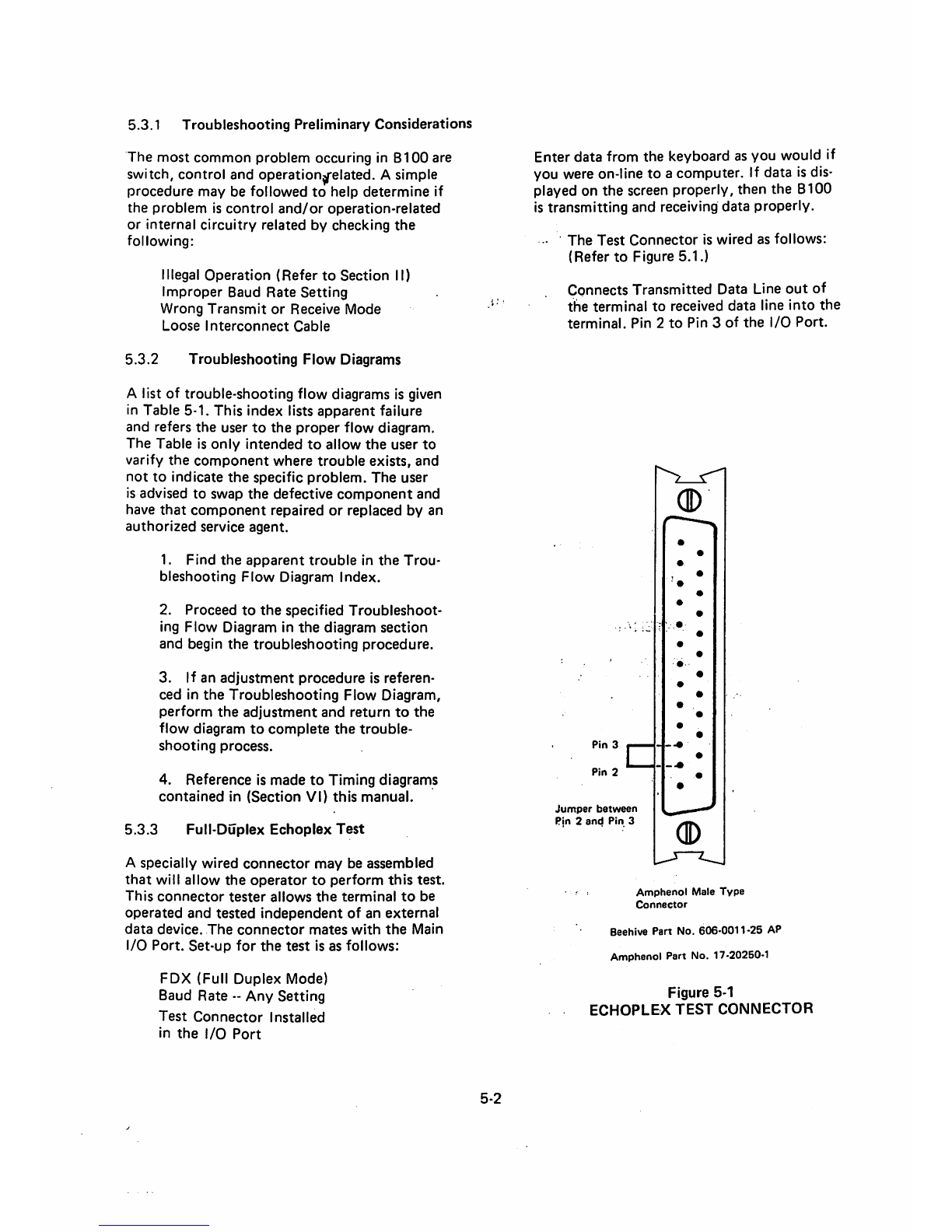
5.3.3
Full-DOplex
Echoplex
Test
A
specially
wired
connector
may
be
assembled
that
will
allow
the
operator
to
perform
this
test.
This
connector
tester
allows
the
terminal
to
be
operated
and
tested
independent
of
an
external
data
device.
The
connector
mates
with
the
Main
I/O
Port.
Set-up
for
the
test
is as follows:
FDX (Full
Duplex
Mode)
Baud
Rate
--
Any
Setting
Test
Connector
Installed
in
the
I/O
Port
5-2
Enter
data
from
the
keyboard as you would if
you were on-line to a computer. If data is dis
played on the screen properly, then the 8100
is transmitting
and
receiving
data
properly.
•
The
Test
Connector
is
wired
as
follows:
(Refer
to
Figure
5.1.)
Connects
Transmitted
Data Line
out
of
the
terminal
to
received
data
line
into
the
terminal.
Pin
2
to
Pin
3
of
the
I/O
Port.
Pin
3
Pin
2
Jumper
between
Pjn 2
and
Pin 3
CD
0
Amphenol
Male
Type
Connector
Beehive Part No.
606-0011-25
AP
Amphenol Part No. 17-20250-1
Figure
5-1
ECHOPLEX
TEST
CONNECTOR

Table5-1. Troubleshooting Flow
Diagram
Index
Apparent
Failure
Troubleshooting
Flow
Diagram
GENERAL
No
raster
present
>
5-1A
No
raster
present
5-1B
OFF
LINE
Cursor
either absent,multiplecursors, cursornot in homeposition or
screen
filled
with
video
blocks
5-2A
Nocharacter displayed when written,non cursor advance
5-2B
Wrong character displayed
5-2C
No
escape
functions
5-2D
No
control
functions
5-2E
ON
LINE
No
data
being
transmitted
5-3A
Transmits
invalid
data
5-3B
No
reception
5-3C
Receives invalid data
and/or
improper parity
5-3D
DISPLAY
Alldisplayed characters out of focus
5-4A
Rolling
display
5-4B
Display
too tall/short for
screen
size
5-40
Height
of displayed characters uneven
5-4D
Display
too wide/narrow for
screen
size
5-4E
Display
not
centered
5-4F
Tilted
display
5-4G
Others
A. Single vertical line
B. Physical
damage
C.
Dot
in
center
of
screen
D. Uneven
intensity/focus
E.
Burned
phosphor
F. Uneven display dimensions
G. Excessive H.V.
Arcing
5-4
H
5-3

START
IS
KBD
PLUGGED
IN
YES
IS
•^BRIGHTNESS""
CONTROL
ADJ
YES
IS
MONITOR
PLUGGED
IN
YES
IS
15VDC
PRESENT
.MON
PI2-6.
YES
IS
HORIZ
DRIVE
SIGNAL
PRESEN
NO
PLUG
IN
KEYBOARD
ADJUST
BRIGHTNESS
CONTROL
AT
REAR
OF
UNIT
NO
PLUG
MONITOR
IN
IS
PROBLEM
SOLVED
IS
PROBLEM
SOLVED
IS
PROBLEM
SOLVED
PRESENT
NO
^^^GIC
CAR^^
1
YES
REPLACE
WIRING
HARNESS
FROM
LOGIC
CARD
TO
MONITOR
N
LOGIC
CARD
BOARD
YES
REPL
MON
ACE
ITOR
5-1A
(ZED
5-4
Table of contents
Other Beehive International Desktop manuals


