BEER Cold Rack / Refrigerated Display Cabinets Assembly instructions

Cold Rack / Refrigerated Display Cabinets
Presentation of Cold Food & Beverages
Installation and programming manual
(for appliances from 2015 onwards)
Attention:
This manual is intended for service technicians,
shopfitters and refrigeration specialists only!

Beer Grill AG
Beer Grill GmbH
Allmendstrasse 7
Tel. +41 56 618 7800
Körnerstrasse 14 a
Tel. +49 71 61 659 876
CH –5612 Villmergen,
Switzerland
Fax +41 56 618 7849
D –79539 Lörrach,
Germany
Fax +49 71 61 659 879
www.beergrill.com
Assembly-Programming-Instructions_Cold-Rack_e_05-10-2018 Page 2
Contents
1 Installation and commissioning ............................................................................................4
1.1 Acceptance ...................................................................................................................4
1.2 Place of installation .......................................................................................................4
1.3 Preparation....................................................................................................................5
1.4 Mobile version...............................................................................................................5
1.5 Installation options.........................................................................................................5
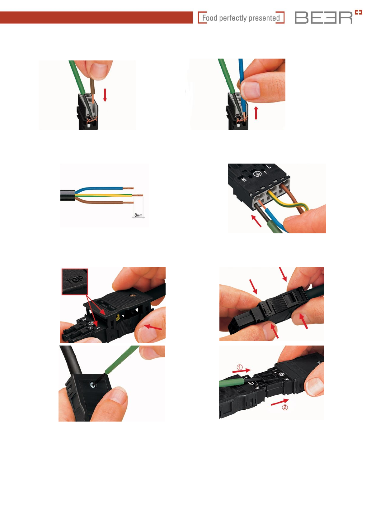
1.6 Connection to the customer's integrated system............................................................5
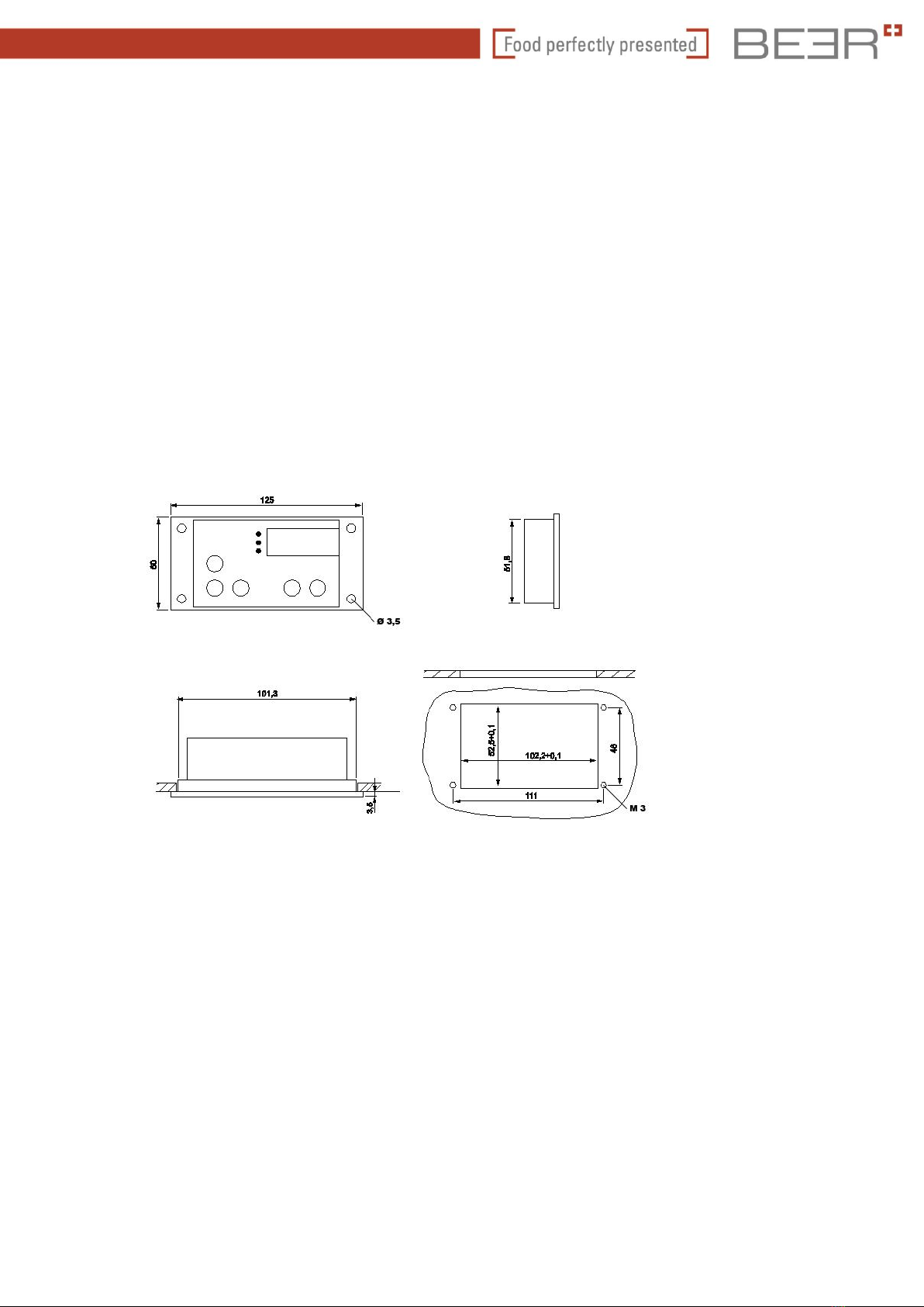
1.7 Possible installation of the control panel for the installation variant................................6
1.8 Step-by-step instructions for installation and commissioning.........................................9
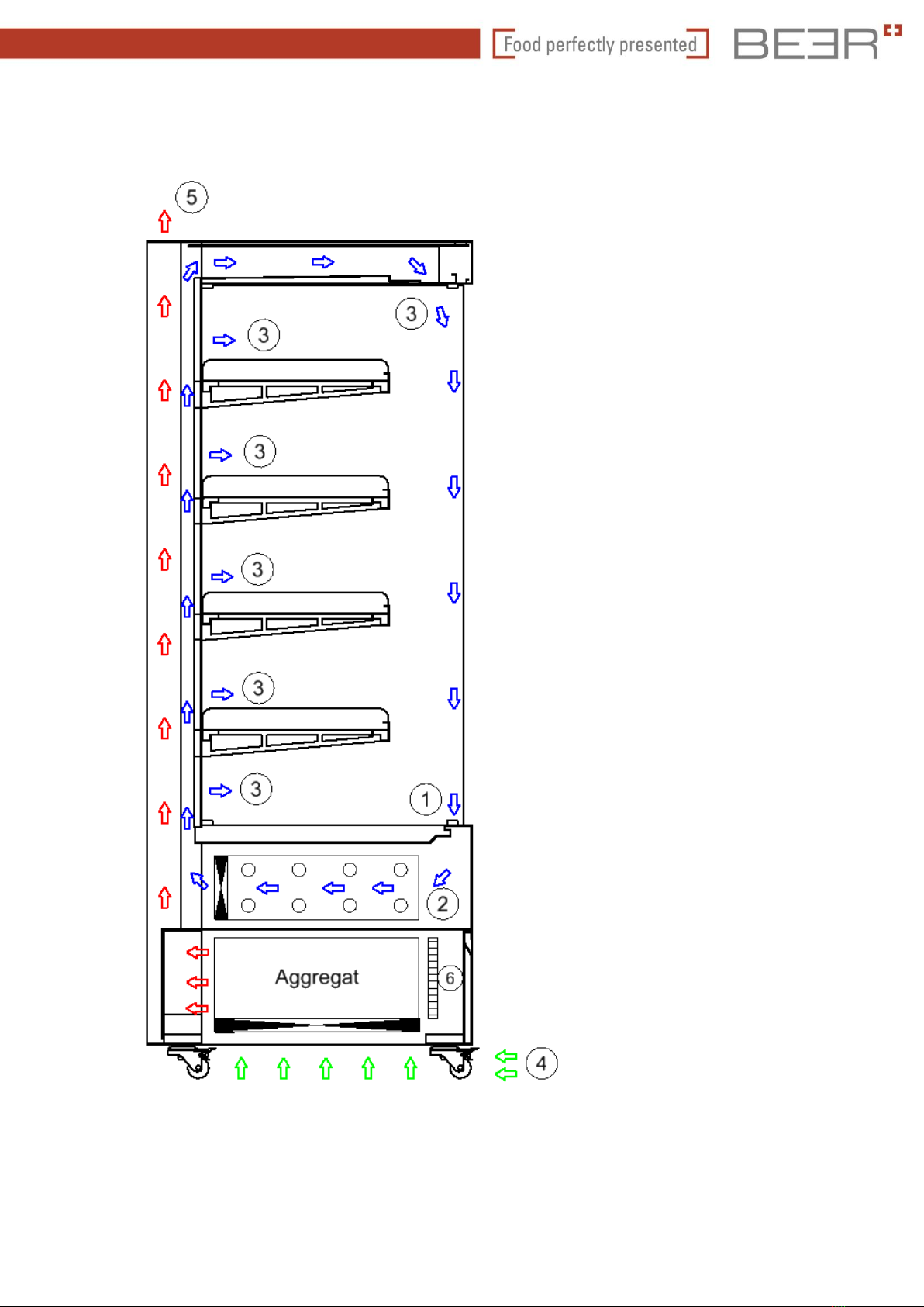
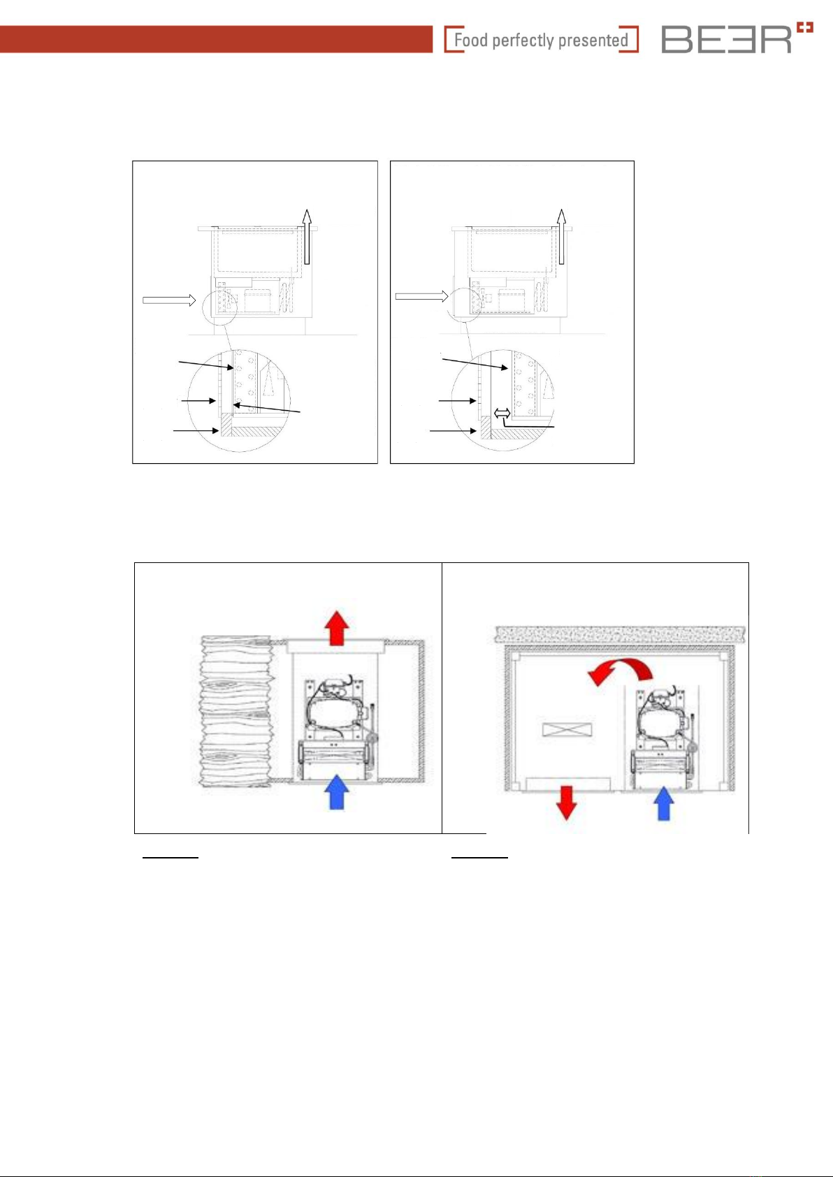
1.9 Functionality of the showcase, air ducts ......................................................................10
1.10 Avoiding the worst error in installation .........................................................................11
1.11 Two installation options...............................................................................................12
1.12 Air routing for self-cooled appliances...........................................................................12
1.13 Drawings and technical data........................................................................................14
1.14 Installation and mounting instructions for wall positioning............................................14
2 General information concerning the control unit.................................................................14
2.1 Product description......................................................................................................14
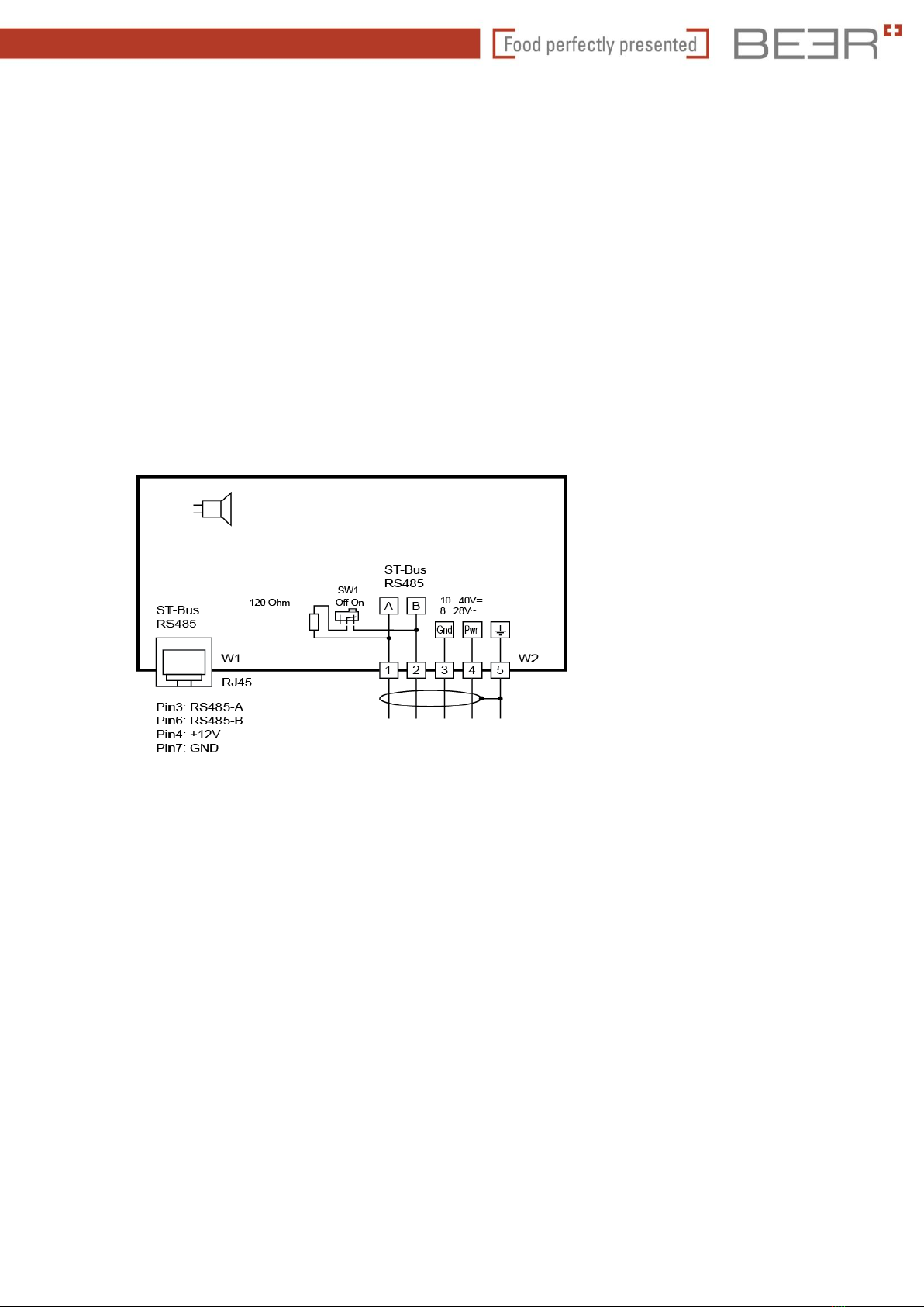
2.2 Control box circuit diagram..........................................................................................15
2.3 Operating panel (display) ............................................................................................16
2.4 Wiring diagram............................................................................................................17
3 Parametrisation..................................................................................................................18
3.1 Description of the operating keys.................................................................................19
3.2 Parametrisation information.........................................................................................20
3.3 Status displays and error messages............................................................................26
3.4 Technical data for display:...........................................................................................27
4 Technical data of the control system..................................................................................28
4.1 ST-Box parameter groups ...........................................................................................28
4.2 Most important variable parameter values, basic parameters......................................29
4.3 Status messages.........................................................................................................41
4.4 Error messages...........................................................................................................41
4.5 Parameter description .................................................................................................42
4.6 Technical data for control box ST 200.........................................................................52
5 Customer service...............................................................................................................53

Beer Grill AG
Beer Grill GmbH
Allmendstrasse 7
Tel. +41 56 618 7800
Körnerstrasse 14 a
Tel. +49 71 61 659 876
CH –5612 Villmergen,
Switzerland
Fax +41 56 618 7849
D –79539 Lörrach,
Germany
Fax +49 71 61 659 879
www.beergrill.com
Assembly-Programming-Instructions_Cold-Rack_e_05-10-2018 Page 3
Subject to technical changes without prior notice
Before installing and putting the refrigerated cabinets into operation, please read these
instructions carefully and strictly follow the information it contains. They contribute to the
professional installation and function of the refrigerated cabinet.
Failure to observe these instructions may void the warranty!
Indicates all instructions that are important for safety. Failure to observe them can lead
to injury, damage to the appliance or to equipment!
!
i

Beer Grill AG
Beer Grill GmbH
Allmendstrasse 7
Tel. +41 56 618 7800
Körnerstrasse 14 a
Tel. +49 71 61 659 876
CH –5612 Villmergen,
Switzerland
Fax +41 56 618 7849
D –79539 Lörrach,
Germany
Fax +49 71 61 659 879
www.beergrill.com
Assembly-Programming-Instructions_Cold-Rack_e_05-10-2018 Page 4
1 Installation and commissioning
1.1 Acceptance
After a final inspection, our appliances are safely packaged in order to arrive in good
condition. Nevertheless, we ask you to inspect the appliances for transport damage when
they are received.
Should you find any damage, please note this on the shipper's papers and on your form and
have the damage confirmed. If the damage does not appear until after unpacking, you must
inform us immediately of the damage in writing. It is advisable to inform your supplier in
advance by telephone.
After inspection, we recommend packing the appliances again to prevent damage
during any intermediate storage or further transport.
The transport is at your own risk; if you do not report transport damage in due time, your
claim for settlement will expire.
1.2 Place of installation
The refrigerated appliances should be installed in such a way that draughts are avoided or
kept to a minimum. Refrigerated appliances should not be installed near doors or in areas
where they are exposed to considerable air circulation, e.g. outlet openings of air
conditioning, ventilation and heating systems.
When designing the ventilation systems, the air velocity and air flow direction above the
refrigerated appliance should be taken into account. Special attention should be paid to the
outlet openings of warm air heating systems.
Heat radiation and lighting
In order to minimise the adverse effects of radiant heat, it is important to ensure that the
refrigerated appliances are not exposed to solar radiation, air distributors and ducts,
uninsulated roofs or walls heated by solar radiation or other sources of heat. Heat radiation
entering the refrigerated appliance leads to greater operating costs and poor performance.
Spotlights or other concentrated lighting fixtures should not be directed into the appliance.
Avoid steam-generating appliances in the vicinity. This can lead to heavy icing of the
evaporator, thus reducing its capacity.
For installation, choose a room that is well ventilated and low in dust. The function of the
refrigerated appliance is only assured if a relative humidity of max. 65 % and a room
temperature of 26 °C are not constantly exceeded.
Correct installation and trouble-free operation are prerequisite for commissioning
the refrigerated cabinet. The installation must comply with local refrigeration,
electrical, safety and hygiene regulations.
i

Beer Grill AG
Beer Grill GmbH
Allmendstrasse 7
Tel. +41 56 618 7800
Körnerstrasse 14 a
Tel. +49 71 61 659 876
CH –5612 Villmergen,
Switzerland
Fax +41 56 618 7849
D –79539 Lörrach,
Germany
Fax +49 71 61 659 879
www.beergrill.com
Assembly-Programming-Instructions_Cold-Rack_e_05-10-2018 Page 5
1.3 Preparation
The refrigerated showcases are easy to install with a minimum of tools and can be placed
on any type of substructure/floors that are strong enough.
For protection, the refrigerated showcase has been provided with a working plastic
protective film. Remove this from the refrigerated appliance. Your refrigerated appliances
should work efficiently.
Any qualified person can complete the major part of the installation. However, all electrical
installations must be carried out by a qualified electrician. Ensure that suitable personnel
and tools are available to prevent damage and injury.
All appliances require a 230 volt power supply. The settings for the appliances can be found
in the enclosed programming manual. As a result of condensation, all refrigerated
appliances must have an external condensation drain or a condensation tray.
1.4 Mobile version
In the case of mobile appliances, the castors must be braked after the appliance has been
placed in its final position.
1.5 Installation options
The appliances can be placed in a niche provided by the customer. The appliance can be
placed directly on the floor or on an elevated surface. Note that a service door as well as
access to the cooling unit and control system are provided on the customer side.
For the dimensions of the appliance, please refer to the order or the attached product
sheets.
1.6 Connection to the customer's integrated system
In the case of centrally cooled appliances, the solenoid valve must be provided by the
customer. Beer Grill attaches the corresponding electrical valve and the injection nozzle
separately to the appliance for customer connection to the integrated system.
Before fixing the refrigerated appliance in place, check again that it is correctly
aligned. The condensation drain must be the lowest point in the inner tank. Check
that water can drain out from the inside of the tank.
!

Beer Grill AG
Beer Grill GmbH
Allmendstrasse 7
Tel. +41 56 618 7800
Körnerstrasse 14 a
Tel. +49 71 61 659 876
CH –5612 Villmergen,
Switzerland
Fax +41 56 618 7849
D –79539 Lörrach,
Germany
Fax +49 71 61 659 879
www.beergrill.com
Assembly-Programming-Instructions_Cold-Rack_e_05-10-2018 Page 6
1.7 Possible installation of the control panel for the installation variant
For ready-to-connect refrigeration appliances, the control panel is mounted under the
cooling tank on the side of the compressor unit. In the case of centrally cooled appliances,
the control system (including the connector plug) is mounted flat under the showcase tank.
The display is enclosed separately.
Each control system consists of the operating panel (display) and the power electronics.
The operating panel is connected to the power electronics via a 2-m ST bus cable.
The operating panel is built for installation in a control panel, front-side stainless steel
panelling.
External dimensions 125 x 60 mm
Panel mounting cutout 102.2 x 52.5 mm, see drawing
Installation depth 22 mm (without bus mating connector) with plug approx. 50 mm

Beer Grill AG
Beer Grill GmbH
Allmendstrasse 7
Tel. +41 56 618 7800
Körnerstrasse 14 a
Tel. +49 71 61 659 876
CH –5612 Villmergen,
Switzerland
Fax +41 56 618 7849
D –79539 Lörrach,
Germany
Fax +49 71 61 659 879
www.beergrill.com
Assembly-Programming-Instructions_Cold-Rack_e_05-10-2018 Page 7
Dimensions of the power electronics

Beer Grill AG
Beer Grill GmbH
Allmendstrasse 7
Tel. +41 56 618 7800
Körnerstrasse 14 a
Tel. +49 71 61 659 876
CH –5612 Villmergen,
Switzerland
Fax +41 56 618 7849
D –79539 Lörrach,
Germany
Fax +49 71 61 659 879
www.beergrill.com
Assembly-Programming-Instructions_Cold-Rack_e_05-10-2018 Page 8
Use a screwdriver (2.5 mm) for wiring.
For safety reasons, extend the PE cable (green/yellow) by 8 mm.
The plugs snap in. Use a screwdriver to disconnect them.

Beer Grill AG
Beer Grill GmbH
Allmendstrasse 7
Tel. +41 56 618 7800
Körnerstrasse 14 a
Tel. +49 71 61 659 876
CH –5612 Villmergen,
Switzerland
Fax +41 56 618 7849
D –79539 Lörrach,
Germany
Fax +49 71 61 659 879
www.beergrill.com
Assembly-Programming-Instructions_Cold-Rack_e_05-10-2018 Page 9
1.8 Step-by-step instructions for installation and commissioning
Unpacking
Each appliance is delivered packed in a wooden/cardboard crate. Position the appliance as
close to the final location as possible and remove the transport packaging, adhesive tapes
and plastic protection films. Involve a second person to help prevent the appliance from
tipping over.
Preparations at the place of installation
Make sure that the place of installation, furniture panels and counters are prepared
according to the technical specifications.When installing the appliance in its location, protect
the surface from possible damage during installation.
The appliance must be aligned horizontally.
Main installation
In any case, the assistance of another person is required to guide the cables of the control
panel and the power supply in order to avoid pinching the cables when the appliance is set
down.
After installation and mounting, make sure that the cooling unit is accessible for service and
repair purposes.
When the appliance has been positioned correctly, it must be levelled horizontally using the
levelling feet.
Voltage
Before connecting the appliance, compare the operating voltage indicated on the rating
plate with the local power supply.
Possibility of disconnecting from the mains
If a connector plug is used for the mains connection, the socket must be easily accessible
in order to disconnect the appliance from the mains when necessary (for cleaning or
maintenance work).
If direct cabling is used, it must be possible to disconnect the appliance from the mains if
necessary.
Attention: Condensation disposal
Since your appliance operates in an open area, the daily amount of condensation can be up
to 10 litres. The condensation water must be drained by the customer (HD 52 connecting
pipe). An odour trap (syfon) is required. If a drainage outlet by the customer is not possible,
use the condensation tray that must be emptied manually.

Beer Grill AG
Beer Grill GmbH
Allmendstrasse 7
Tel. +41 56 618 7800
Körnerstrasse 14 a
Tel. +49 71 61 659 876
CH –5612 Villmergen,
Switzerland
Fax +41 56 618 7849
D –79539 Lörrach,
Germany
Fax +49 71 61 659 879
www.beergrill.com
Assembly-Programming-Instructions_Cold-Rack_e_05-10-2018 Page 10
1.9 Functionality of the showcase, air ducts
1) Cold air intake, must always be kept
clear.
2) Evaporator (cold exchanger), must not
be iced up or dusty.
3) Cold air discharge from the rear wall,
must not be completely blocked.
4) Ambient air intake, for cooling the unit,
must not be blocked.
5) Hot air outlet from the unit must always
be guaranteed. Otherwise the heat
cannot be dissipated and the showcase
cannot provide the required cooling
capacity.
6) Cooling honeycomb ambient air intake,
must always be kept clean and dust-
free.

Beer Grill AG
Beer Grill GmbH
Allmendstrasse 7
Tel. +41 56 618 7800
Körnerstrasse 14 a
Tel. +49 71 61 659 876
CH –5612 Villmergen,
Switzerland
Fax +41 56 618 7849
D –79539 Lörrach,
Germany
Fax +49 71 61 659 879
www.beergrill.com
Assembly-Programming-Instructions_Cold-Rack_e_05-10-2018 Page 11
1.10 Avoiding the worst error in installation
Correct ventilation of the cooling unit in ready-to-connect appliances is an essential point for
proper functioning of the refrigerated cabinets. The energy extracted from the area around
the goods and the heat generated by the unit's electrical energy absorption must be
dissipated from the cooling unit –this is the only way the refrigeration circuit can function.
A) Cooling unit
The unit pumps the gaseous refrigerant
through the cooling system.
B) FAN
The fan draws in cold ambient air that cools
the unit and the hot gas in the condenser.
C) CONDENSER
This is a heat exchanger that releases the heat
extracted from the cooling area back into the
circulating air. Gaseous refrigerant is liquefied
again by the heat dissipation.
Avoid heated exhaust air being mixed with cold air from the surroundings and
sucked into the appliance again. If the heat generated by the unit and refrigerant
is no longer led away (thermal short circuit), the refrigerated appliance will not
function properly.
NO!
NO!
Warm exhaust air
Cold air (from the room)
i

Beer Grill AG
Beer Grill GmbH
Allmendstrasse 7
Tel. +41 56 618 7800
Körnerstrasse 14 a
Tel. +49 71 61 659 876
CH –5612 Villmergen,
Switzerland
Fax +41 56 618 7849
D –79539 Lörrach,
Germany
Fax +49 71 61 659 879
www.beergrill.com
Assembly-Programming-Instructions_Cold-Rack_e_05-10-2018 Page 12
1.11 Two installation options
1.12 Air routing for self-cooled appliances
Serving-side
Serving-side
Variant 1
Air flow directly through the cooling unit, blown
out in a straight line.
Variant 2
Air intake and warm air outlet channelled on the
same side.
Optional: Additional fan
The air opening of the panelling is less than 5
mm from the condenser:
Air inlet for
cold air
Outlet opening
for warm air
Front of
condenser
housing
Removable
fan grille
housing
Counter
panelling
housing
Narrow gap
between the
condenser
housing and
panelling:
Close this gap
with sealing
tape.
Avoid the gap
between the
condenser housing
and panelling:
a) Close this gap
with wood or
sheet metal.
b) Pull the
condenser unit
forward to the
panelling.
Air inlet
for cold air
Front of
condenser
housing
Removable
fan grille
housing
Counter
panelling
housing
The air opening of the panelling is more than 5
mm from the condenser:
Outlet opening
for warm air
CORRECT!
INCORRECT!

Beer Grill AG
Beer Grill GmbH
Allmendstrasse 7
Tel. +41 56 618 7800
Körnerstrasse 14 a
Tel. +49 71 61 659 876
CH –5612 Villmergen,
Switzerland
Fax +41 56 618 7849
D –79539 Lörrach,
Germany
Fax +49 71 61 659 879
www.beergrill.com
Assembly-Programming-Instructions_Cold-Rack_e_05-10-2018 Page 13
Whatever method is used, make sure that the incoming cold air reaches the interior through
the condenser surface only and that no warm exhaust air is sucked in from the interior of
the counter.
If the exhaust air is not routed out through an air duct, an additional exhaust fan can help
transport the warm exhaust air out of the counter base unit. Especially with option 2, this
provides better cooling of the refrigeration unit.
With aeration and ventilation on one side (variant 2), the distance between the
ventilation openings should be as large as possible –at least 150 % flow diameter
compared with the intake area –in order to prevent the warm exhaust air from being
sucked in.
Make sure that the intake opening and the air outlet opening are large enough. The air flow
must not be interrupted or obstructed; the warm exhaust air must be able to exit the unit
room unhindered. The inlet and outlet openings must not be blocked or obstructed by the
customer/operating company during operation.
A protective grid or shutter in the intake area is recommended to avoid damage to the fins
of the condenser and the associated risk of injury to the user.
Use the solution that is most convenient for you.
The available ventilation grids often reduce the actual cross-section and thus the intake and
exhaust air openings. Shutters that are too angled can also increase air resistance, thus
restricting air removal.
The outlet opening (flow diameter) for the exhaust air should be at least 1.5 x
the size of the condenser surface!
The cooling unit returns the thermal energy of the goods to the environment via
the condenser. If this output is impaired, this leads to lower cooling capacity or,
in the worst case, to a defective unit.
i
!

Beer Grill AG
Beer Grill GmbH
Allmendstrasse 7
Tel. +41 56 618 7800
Körnerstrasse 14 a
Tel. +49 71 61 659 876
CH –5612 Villmergen,
Switzerland
Fax +41 56 618 7849
D –79539 Lörrach,
Germany
Fax +49 71 61 659 879
www.beergrill.com
Assembly-Programming-Instructions_Cold-Rack_e_05-10-2018 Page 14
1.13 Drawings and technical data
For the device dimensions and technical data, please refer to your order confirmation.
1.14 Installation and mounting instructions for wall positioning
For the device dimensions and technical data, please refer to your order confirmation.
2 General information concerning the control unit
The ST 200 & 521 controller series are intended for general use in refrigeration systems.
2.1 Product description
The ST-BOX 200 is used for thermostatic temperature control of refrigeration systems. The
controller can be supplied with 90...250 V AC and has four output relays that can be freely
programmedto control a compressor, an evaporator fan, lighting or other necessaryoutputs.
An output for DC fans is also available. It is operated either directly on the box or via a
separate, connectable display.
The ST-BOX has a three-digit display, 3 operating keys and 7 LEDs that are also used to
indicate the status of the relay outputs. The parameters are set at various operating levels,
where access is increasingly difficult for reasons of security.
The controller is networked via an ST bus interface.
Sensor Pt100, PTC, 4...20 mA
Housing dimensions 185 mm x 170 mm x 76 mm
Impermeability Front IP20
Connection WAGO connector plug

Beer Grill AG
Beer Grill GmbH
Allmendstrasse 7
Tel. +41 56 618 7800
Körnerstrasse 14 a
Tel. +49 71 61 659 876
CH –5612 Villmergen,
Switzerland
Fax +41 56 618 7849
D –79539 Lörrach,
Germany
Fax +49 71 61 659 879
www.beergrill.com
Assembly-Programming-Instructions_Cold-Rack_e_05-10-2018 Page 15
2.2 Control box circuit diagram
Ver. 1.11
F3
F2
Pt100
PTC
90...250V~
max. 16A
PTC
24V=
0...100%
F4
4...20mA
0...100%r.H.
S
16(9)A
250V~ 16(2,2)A
250V~ 16(2,2)A
250V~
16(2,2)A
250V~
(inrush)
S1
0...24V
max.
2A
K1 K2 K3 K4
F1
Pt100
PTC
Commander
Bedienung
K1: Verdichter
K2:Abtauen
Operation
Satellite display
Compressor
Defrosting

Beer Grill AG
Beer Grill GmbH
Allmendstrasse 7
Tel. +41 56 618 7800
Körnerstrasse 14 a
Tel. +49 71 61 659 876
CH –5612 Villmergen,
Switzerland
Fax +41 56 618 7849
D –79539 Lörrach,
Germany
Fax +49 71 61 659 879
www.beergrill.com
Assembly-Programming-Instructions_Cold-Rack_e_05-10-2018 Page 16
2.3 Operating panel (display)
Key 1
UP key
Press this key to increase the parameter value.
Press the UP key for 3 seconds to start defrosting at any
time.
Key 2
DOWN key
Press this key to decrease the parameter value. An alarm
can be acknowledged with the DOWN key.
Key 3
LIGHT key
Off/On key for external lighting (if present).
Key 4
SET key
While the SET key is pressed,the setpoint is displayed. The
SET key is also used for parameter setting.
Key 5
ON/OFF key
This key can be used to switch the cooling ON or OFF.
Key 6
Not used
Lamp 7
Cooling mode
Lamp 8
Defrost mode
Lamp 9
Fan

Beer Grill AG
Beer Grill GmbH
Allmendstrasse 7
Tel. +41 56 618 7800
Körnerstrasse 14 a
Tel. +49 71 61 659 876
CH –5612 Villmergen,
Switzerland
Fax +41 56 618 7849
D –79539 Lörrach,
Germany
Fax +49 71 61 659 879
www.beergrill.com
Assembly-Programming-Instructions_Cold-Rack_e_05-10-2018 Page 17
Product description
The ST521 operating panel is equipped with an RJ45 connector plug and thus serves as an
operating panel for a remote ST-BOX. It has six keys and a three-digit LED display. The
operating panel is networked over the RJ45 interface.
Front dimensions 125 x 60 mm
Installation dimension (WxHxD) 102.2 mm x 52.5 mm x min. 50 mm
Impermeability Front IP65
Connection RJ45
2.4 Wiring diagram
Ver. 1.11
Terminating
resistor

Beer Grill AG
Beer Grill GmbH
Allmendstrasse 7
Tel. +41 56 618 7800
Körnerstrasse 14 a
Tel. +49 71 61 659 876
CH –5612 Villmergen,
Switzerland
Fax +41 56 618 7849
D –79539 Lörrach,
Germany
Fax +49 71 61 659 879
www.beergrill.com
Assembly-Programming-Instructions_Cold-Rack_e_05-10-2018 Page 18
3 Parametrisation
Ver. 1.11
Parameter groups:
L - - Networking and display
b - - Key functions
J - - Predefined parameter sets
A - - Display
Parameter –operating unit:
Parameter –controller:

Beer Grill AG
Beer Grill GmbH
Allmendstrasse 7
Tel. +41 56 618 7800
Körnerstrasse 14 a
Tel. +49 71 61 659 876
CH –5612 Villmergen,
Switzerland
Fax +41 56 618 7849
D –79539 Lörrach,
Germany
Fax +49 71 61 659 879
www.beergrill.com
Assembly-Programming-Instructions_Cold-Rack_e_05-10-2018 Page 19
3.1 Description of the operating keys
UP key (1)
Press this key (1) to increase the parameter or parameter value. A further function of the
key can be defined using parameter b1. In addition to the value setting, the UP key
performs other functions. Pressing the UP key for 3 seconds triggers unscheduled
defrosting of the refrigeration system.
DOWN key (2)
Pressing this key (2) decreases the parameter or parameter value. A further function of
the key can be defined using parameter b2. In addition to the value setting, the DOWN
key performs otherfunctions. Inthe event of an alarm with the associated triggered buzzer
sound, pressing the DOWN key can be used to acknowledge the buzzer sound.
SET key (4)
Press the SET key (4) to display the setpoint.
Light key (3)
The key function (3) can be defined using parameter b4.
Option key (6)
The key function (6) can be defined using parameter b5.
ON/OFF key (5)
The key function (5) can be defined using parameter b6. Pressing the ON/OFF key during
operation (for at least 3 seconds) switches the refrigeration controller off completely. The
controller can be switched back on by pressing the ON/OFF key again.
The operating panel is always operated with the UP, DOWN and SET keys. The standard
display shows the temperature of the cooling space (average actual temperature). Press
the SET key (4) to switch the display to the cooling space temperature (setpoint
temperature) required by the user.
The setpoint temperature can only be changed by simultaneously pressing the SET and
UP or SET and DOWN keys. While pressing the keys, the changed setpoint can be read
on the display. After changing the setpoint temperature and releasing the keys, the actual
temperature reappears on the display. This is the default method of setting values.

Beer Grill AG
Beer Grill GmbH
Allmendstrasse 7
Tel. +41 56 618 7800
Körnerstrasse 14 a
Tel. +49 71 61 659 876
CH –5612 Villmergen,
Switzerland
Fax +41 56 618 7849
D –79539 Lörrach,
Germany
Fax +49 71 61 659 879
www.beergrill.com
Assembly-Programming-Instructions_Cold-Rack_e_05-10-2018 Page 20
3.2 Parametrisation information
Ver. 1.11
Information: This chapter is intended for technical personnel only.
The refrigeration controller is parametrised either at the factory or when a refrigeration
system is commissionedby qualified personnel. Any incorrect or improper parameter setting
can lead to malfunctions and thus damage to the chilled goods. The parameter setting can
only be made with the help of one or more passwords. The following parameter list details
all parameters of a complex refrigeration controller. However, it is important to bear in mind
that the listed parameters only work in controller versions where the appropriate hardware
(outputs, inputs, sensors and internal clock) is available.
The parametrisation can be carried out at any time. The control is not interrupted by the
parametrisation, but can directly influence it. If no key is pressed for 2 minutes, the process
is aborted and the actual value displayed again.
To enter the parametrisation process, press the UP and DOWN keys simultaneously. After
approx. 3 seconds the code word PA appears on the display. Press the UP or DOWN key
to switch between the code words PA and PAE.
All other settings or value defaults in the parameter level are made using thegeneral method
of value setting, i.e. by simultaneously pressing the SET, UP or DOWN keys.
PA input for the display password
Selecting the code word PA provides the option of setting a password required for
parametrisation. After entering the password -19, the display shows the name of the first
parameter group of the operating panel, L--,b--,J--,A--. It is now possible to select a
parameter very quickly using the UP and DOWN keys.
PAE input for the control system password on the external control panel
Selecting the code word PAE provides the option of setting a password required for
parametrisation. After entering the password -38, the display shows the name of the first
parameter group of the connected controller, A-- and others. It is now possible to select one
of the parameter groups very quickly using the UP and DOWN keys.
Important information:
The same parameters or parameter groups can occur for PA (internal, display) and PAE
(external, controller).
After selecting a parameter group, it is normally sufficient to press the SET key (--- appears
on the display) and then release the key. The first parameter of the parameter group then
appears (e.g. in parameter group A--, parameter A0).
!
Table of contents
Other BEER Commercial Food Equipment manuals
Popular Commercial Food Equipment manuals by other brands

Rational
Rational iCombi Pro Original Installation Instructions

Prismafood
Prismafood DMA 310/1 manual

CombiSteel
CombiSteel 7090.0020 user manual

KitchenAid
KitchenAid KUBR314K Use and care guide and installation instructions

KoolMore
KoolMore KM-ICD-26SD user manual

saro
saro ES 903 PZ 1/4 operating instructions