Sigma CHEF 10 User guide

Instructions manual CHEF 10 VVE 1 of 19
Via Artigianato 85 – 25030 Torbole Casaglia.
(BRESCIA) – ITALY – Tel 030 265 04 79 –Fax 030 265 01 43
USE AND MAINTENANCE INSTRUCTION MANUAL
CHEF 10 PLANETARY MIXER WITH ELECTRONIC SPEED
VARIATION (INVERTER)

Instructions manual CHEF 10 VVE 2 of 19
USE AND MAINTENANCE INSTRUCTION MANUAL
CHEF 10 PLANETARY MIXER WITH ELECTRONIC SPEED
VARIATION (INVERTER)
This instructions, use and maintenance manual provides the instructions necessary for
transportation, starting-up, use and maintenance of the mixer. It must be consulted before any
one of these acts.
The manual must be read not only by maintenance technicians, but also by operators in charge
of the mixer who must correctly carry out what is within their line of competence.
The manual is an integral part of the mixer. It must be kept in a suitable place where it can remain intact and
where it can be consulted during the whole life of the machine.
INDEX
SAFETY INSTRUCTIONS........................................................................................................................................................................3
RESIDUAL RISKS ...................................................................................................................................................................................3
RESIDUAL RISKS, PROHIBITIONS, OBLIGATIONS: Summarised table.................................................................................................4
SYMBOLS USED AND QUALIFICATIONS OF THE PERSONNEL..........................................................................................................5
USE AND DESCRIPTION OF THE MIXER..............................................................................................................................................5
INSTRUCTIONS FOR USE .....................................................................................................................................................................6
IDENTIFICATION, POSITION OF THE OPERATOR AND DANGEROUS AREAS...................................................................................8
TECHNICAL DATA, PACKAGING, DIMENSIONS AND WEIGHT ..........................................................................................................9
TRANSPORTATION AND HANDLING.....................................................................................................................................................9
STORAGE..............................................................................................................................................................................................10
INSTALLATION......................................................................................................................................................................................10
PRESERVATION OF THE MIXER.........................................................................................................................................................10
WARRANTY TERMS ............................................................................................................................................................................10
CLEANING AND MAINTENANCE OPERATIONS..................................................................................................................................11
ROUTINE MAINTENANCE .................................................................................................................................................................12
EXTRAORDINARY MAINTENANCE......................................................................................................................................................12
PERIODICAL MAINTENANCE ..............................................................................................................................................................13
SPARE PARTS .....................................................................................................................................................................................13
MAIN COMPONENTS............................................................................................................................................................................13
DISMANTLING AND WASTE DISPOSAL ..............................................................................................................................................13
SPARE PARTS LIST..............................................................................................................................................................................14
BLOCKAGE OF MACHINERY AND NECESSARY REMEDIES.............................................................................................................16
ELECTRICAL LAYOUT .........................................................................................................................................................................16

Instructions manual CHEF 10 VVE 3 of 19
SAFETY INSTRUCTIONS.
The safe and systematic use of the mixer is subordinated to compliance with behaviour and standards listed
hereafter.
Safety standards
Personnel must be in good physical and mental conditions and be adequately instructed on the use
of the mixer having read this publication.
The safety manager of the company, of the operating area and of the department, when choosing
the person who must use this equipment (a person suitable for the job according to Standards in
force), must consider his/her cultural preparation, physical suitability and the psychological aspect
(mental stability, sense of responsibility, etc.). Moreover, based on the attitudes and capacity that
were verified, the manager must provide this person with proper training, having him/her read the
present publication, in order to have full knowledge of the mixer and of the rules of behaviour
applying to it.
The area around the mixer must be well lit, free from other objects and clean.
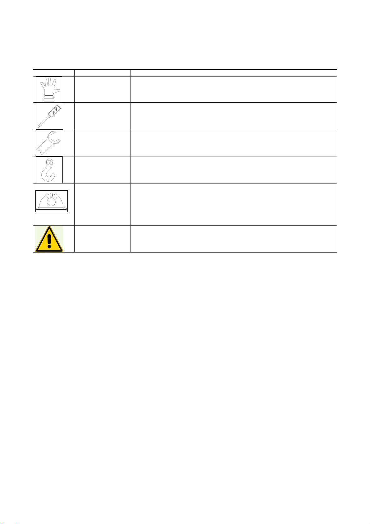
The personnel in charge of running, cleaning and carrying out maintenance on the mixer must wear
the required PPE (personal protective equipment).
Do not wear dangling clothing or fluttering hems (ties, napkins, torn suits, open jackets etc.) to avoid
getting entangled.
During maintenance and cleaning, the operator must disarm the master switch and place the system
in safe conditions (for example, removing the plug).
Never leave the mixer unattended while it is running. Be careful of abnormal noises or behaviour.
Keep away from rotating parts. Never open the grid before the equipment has come to a complete
stop.
At the end of work, empty the machine completely, disconnect the master switch cutting the power,
place it in safe conditions and clean it with a neutral degreasing agent (i.e. with Marseille soap).
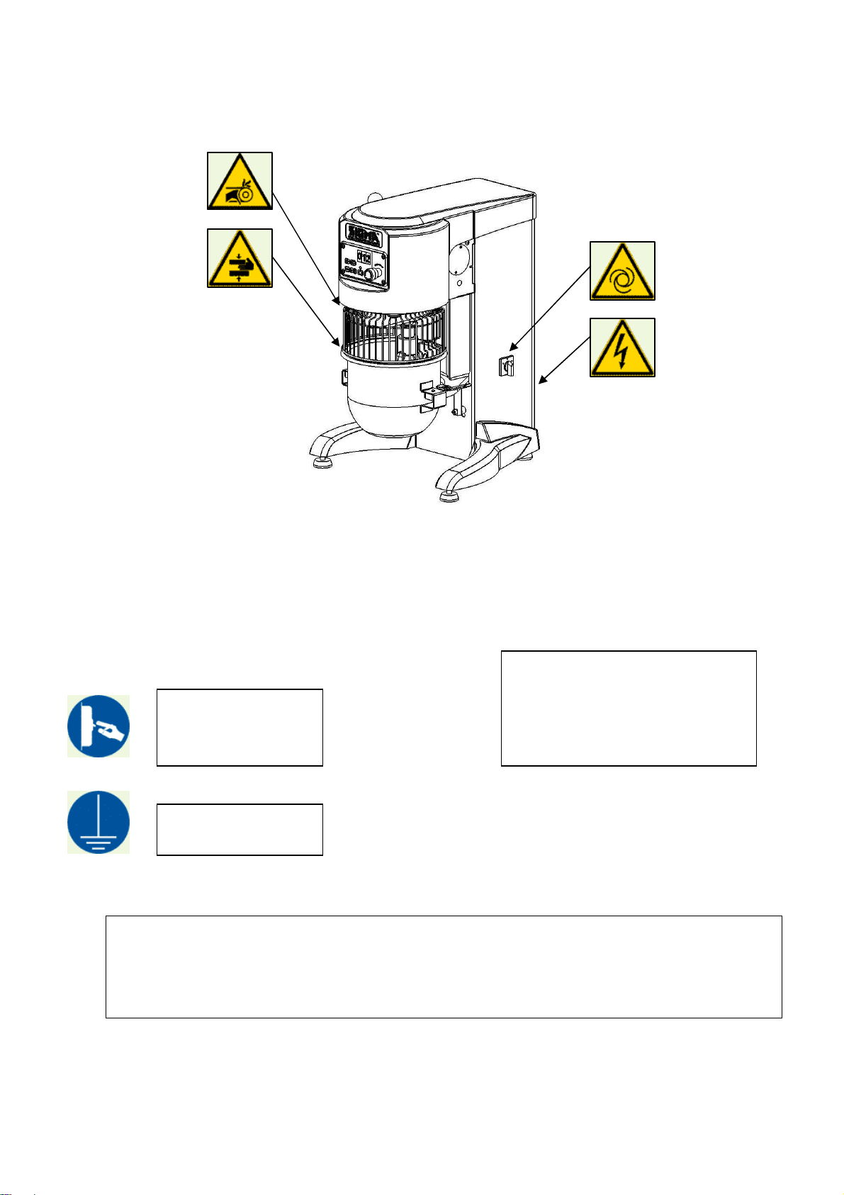
Safety devices.
The mixer is equipped with some devices which protect its operation as well as the safety of the operator.
They must not be removed or modified. Their functioning must be checked periodically.
Master switch: cuts power from the mixer, for maintenance in safe conditions.
Circuit breaker switch: cuts power if the electric motor overheats.
Fixed guards: All casings and guards fixed with screws or mechanical locks can be removed only for
maintenance, by specialised personnel and in the prescribed modalities. When the work is over, they
must be mounted immediately.
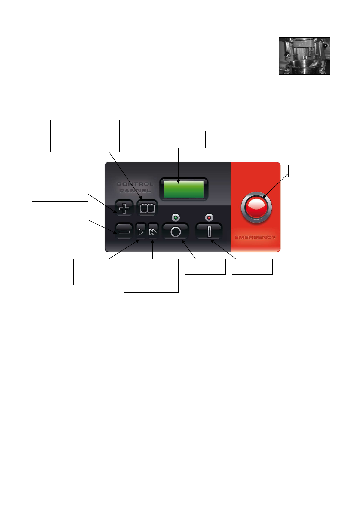
Mobile guards: Movement of the grid activates a micro switch which prevents the mixer from running
if the grid is open. If the grid is lifted while the mixer is running, it stops the cycle unconditionally, just
like an emergency stop. The start button must be pressed for the mixer to restart.
Safety Standards applied to the mixer.
EN 292 Safety of machinery.
EN 294 Minimum distances to prevent accidental contact.
CEI 17-13. Low-voltage switchgear and controlgear assemblies.
Community Directives: 89/392/EEC, 89/336/EEC, 91/368/EEC, 93/44 EEC, 93/68 EEC.
RESIDUAL RISKS
Danger for limbs: Going beyond the protective grid or removing the casing during maintenance, it is
possible to access the moving organs of the mixer.
They are dangerous areas where serious physical injuries can occur. Do not introduce limbs or other
objects without having placed the mixer in safe conditions.
Danger of electrocution: the mixer must not operator without an adequate earthing system. It must
be connected to a system built in compliance with construction standards in force in the country
where it is installed.
Automatic cycle: after starting up the mixer, it follows an automatic operating cycle. Never go past
the safety barriers with your limbs or other objects while it is running.

Instructions manual CHEF 10 VVE 4 of 19
RESIDUAL RISKS, PROHIBITIONS, and OBLIGATIONS: Summarised table.
Obligation to
disconnect mixer
before working on it.
ATTENTION!
Where the required PPE during operations.
Clean the mixer thoroughly after use.
Do not remove the safety devices or protective casings.
Do not introduce any object through the protective grid with organs in movement: danger of objects being thrown.
Before carrying out any manoeuvre beyond the protective grid, wait for the mixer to come to a complete stop.
Stability for machinery: if there is the
possibility of slipping on wet or greasy
surfaces or positioning the equipment in
unstable places (ships, planes or other),
use the appropriate attachments for
stable fixing (4 anchoring devices with
200 kg resistance, M8 screws)
Obligation to carry out
earthing.

Instructions manual CHEF 10 VVE 5 of 19
SYMBOLS USED AND QUALIFICATIONS OF THE PERSONNEL.
The following indicates the qualifications of personnel required to operate the mixer.
The symbols placed on a chapter mean to recall the specific skill needed for the intervention described
therein. Wherever no symbols are present, the chapter applies to everyone.
Symbol Description Features
OPERATOR Person acquainted with operating, adjusting and programming the mixer and its
protection and safety systems, who knows possible work cycles and ingredients
to be used with relative maximum admitted amounts and who has read and
understood the use and maintenance manual.
ELECTRICAL
MAINTENANCE
TECHNICIAN
Person in good health who due to qualification, job or experience is qualified to
carry out the profession of electrical maintenance technician and who has read
and understood the use and maintenance manual.
MECHANICAL
MAINTENANCE
TECHNICIAN
Person in good health who due to qualification, job or experience is qualified to
carry out the profession of mechanical maintenance technician and who has read
and understood the use and maintenance manual.
PERSON IN
CHARGE OF
HANDLING
Person in good health who due to qualification, job or experience is qualified to
carry out handling of loads and who has read and understood the use and
maintenance manual.
ASSISTANCE
Tel. +39
030.2650488
Fax +39
030.2650143
Requesting manua
l updates.
Phone customer assistance concerning functioning, starting or faults of
machinery.
Requesting spare parts, repairs, system overhauls, interventions on site.
Training courses
ATTENTION. This sign requests you to pay particular attention to the operations indicated.
Lack of compliance can cause harm to personnel or damage to the mixer.
USE AND DESCRIPTION OF THE MIXER:
BMC series planetary mixers are mixing derives which are particularly suitable for use in the hotel sector.
The high-power motor is controlled by an electronic speed variator with a transmission ratio that is capable of
a great excursion between low and high speed and a proportional number of rotations of the instrument. The
mixer was built to process, beat, whip and mix food mixtures made up of flour, water, yeast, butter or
margarine, eggs, potatoes (boiled), sugar, cream, minced meat, purée and additives, as long as they are
allowed by law and hygienic standards. It is not allowed to use hardened objects due to freezing or other
reasons.
Adapting the mixer to other work processes would implicate not only modifying the machinery by authorised
personnel but also the amendment of this manual.
The high-power motor, the transmission system and the steel framework make it sturdy and reliable, with a
large size suitable for professional use. The safety devices and electrical control equipment complying with
European Standards complete the machinery.
The electromechanical bowl-lowering device, the easy disassembly of the device and the tools supply the
mixer with great professionalism.
The accessories provided with the machine have been built with the utmost care: whisk, blade and spiral,
together with the shape of the bowl ensure the best mixing results. In order to remove the mixture, turn off
the mixer by switching off the master switch, lower the bowl and remove it by hand. Use a plastic, aluminium
or wooden spatula (which do not scratch the bowl) to make the operation easier.

Instructions manual CHEF 10 VVE 6 of 19
INSTRUCTIONS FOR USE
To be able to work; the bowl must be mounted and the bowl protective grid closed. Otherwise it will be
blocked by the safety systems.
DO NOT REMOVE OR TAMPER WITH THE ELECTRICAL OR MECHANICAL GUARDS OR SAFETY
DEVICES ON THE MACHINE.
The bowl must be in position before the tools. It must be inserted with the bowl lever down,
inserting the appropriate pin welded onto the bowl into the hole on the support arc.
Complete positioning by having the holes on the bowl support plates match with the
centring pins. Block the bowl with the handles.
If it was not previously done, rotate the protective grid of the bowl to the open
position and, after having chosen the tool, insert it into the tool holder shaft.
Once it is inserted, turn the tool clockwise, having the transmission pin enter
the work position as indicated in the figure. Lower it and insert the tool lock
ring.
Using the lever, lift the bowl to the work position and close the protective grid of the bowl. At
this point, after inserting the ingredients, start the work cycle.
ELECTRICAL
PANEL
WITH SIX
PROTECTION
GRID
BOWL
LOCKING
HANDLES
LIFTING LEVER
SPEED CHANGE WITH
THE INVERTER INSIDE
THE UPRIGHT

Instructions manual CHEF 10 VVE 7 of 19
In order to remove the mixture, wait until the tool has stopped. Then turn the protection
grid. Use the lever to lower the bowl and release the tool from the attachment sleeve.
Remove the tool and release the bowl from the handles.
CONTROLS
The control panel is located on the front of the mixer:
To activate the mixer:
•Activate the master switch located on the side of the machine.
•Insert the bowl.
•Insert the tool.
•Lift the bowl to the high position.
•Rotate the protection grid to the closed position.
Programming parameters:
When the mixer is turned on it goes through a short two second test, it verifies mains voltage, grid and bowl
presence alarms. In the mean time full squares that pursue each other appear on the display, they show the
board analysis status, the start and stop LED blink and then SIGMA SYSTEM appears on the screen, the
machine is ready for use.
Programming:
By pressing the menu button for a short a mount of time the following parameters will scroll on the display
1) Language
2) Timer, that is cycle duration time
EMERGENCY
MULTI-LINGUAL
DISPLAY
+ BUTTON FOR
MOVING WITHIN
THE MENU
- BUTTON FOR
MOVING WITHIN
THE MENU
> BUTTON
FOR
DECREASING
THE SPEED
>> BUTTON TO
INCREASE THE
SPEED AND
ENTER THE
SETTINGS
STOP
BUTTON
BUTTON MENU FOR
PROGRAMMING AND
SAVING SETTINGS:
TIMER AND LANGUAGE
START
BUTTON

Instructions manual CHEF 10 VVE 8 of 19
Language:
Using the menu key, besides the machine operation time, it is possible to modify the setting of the
"LANGUAGE" that is used to display messages on the screen.
Press the menu key allowing the settable parameters to scroll until the "LANGUAGE" item appears on the
display, use the >> key to enter and modify the language parameter ad then using the + and - keys select
the language to be used (Italian, English, Spanish, French, Russian).
Once the desired parameter is selected then press the menu key for at least two seconds to memorise the
selected language.
Timer:
Press the menu key allowing the settable parameters to scroll until the display shows “TIMER1.SET1”
Press the >> key to enter the TIMER 1 settings
The first line shows SET 1 while the second one shows “MIN 00”
Using the + and - keys we will set the chosen minutes value, from 0 up to 60 minutes. Once the minutes
have been set, press the menu key until “SEC 00” appears on the display, this value can be set from 0 to 59
seconds.
Once these steps have been completed, to memorise the values that have been inserted up until now one
must press the menu key for at least two seconds and then it goes back to normal board operation.
OPERATION
When starting up, by pressing the start button the machine starts at the lowest speed, the >> key is used to
increase the selected speed, until it reaches the maximum use speed that is the sixth. By pressing the > key
instead it will decrease the speed until it reaches the first.
The work load of the planetary mixers is established by the customer. Very many problems arise from
improper use. If recommended amounts are exceeded, the quality of the product will suffer, as well as the
duration of the mechanical organs of the mixer. See the following table for indications on maximum amounts:
CONDITIONS FOR USE:
APPLICATION INGREDIENT
S BMC-
10 BMC-
20 BMC-
30 BMC-
40 BMC-
60 TYPE OF
TOOL SPEED
Mix with 55% water Flour+W Kg 3 6 9 12 18 Spiral 1 : 2
Pasta for croissants Flour Kg 2,5 5 7 9 15 Spiral 1 : 2
Pasta for profiteroles Flour Kg 2 4 6 8 12 Spiral 1 : 2
Meat Kg 5 10 15 20 30 Spiral/blade 1 : 2
Purée Potatoes Kg
5 10 15 20 30 Blade/whisk 1 : 3
Egg white Number of
eggs 16 32 50 70 96 Whisk 1 : 6
Biscuits Number of
eggs 15 30 45 60 90 Whisk 1 : 4
Meringues Sugar Kg 0,75 1,5 2,25 3 4,5 Whisk 1 : 6
Whipped cream Litres of
cream 2 4 5,5 7 10 Whisk 1 : 6

Instructions manual CHEF 10 VVE 9 of 19
Atmospheric conditions: The mixer needs to be installed inside of lit, ventilated building, on top of a solid and
level support. Temperatures from 5 to 40°C with hum idity no greater than 90%.
Lighting: the light at disposal of the operator must comply with the type of work carried out, in relation to
general lighting, according to the Standards in force. It must on any account be sufficient to read the controls
and danger signs and must not blind the operator.
Vibrations: in correct working conditions, vibrations do not create dangerous situations.
Noise emissions: 70 dbA for normal use.
Electromagnetic environment: the machine has been built to work correctly in an industrial type of
electromagnetic environment.
Environments with risk of explosion: An atmosphere capable to being transformed into an
explosive atmosphere due to room and/or operating conditions is defined a potentially explosive
atmosphere.
The mixer was not built to work in environments with potentially explosive atmospheres.
IDENTIFICATION, POSITION OF THE OPERATOR AND DANGEROUS AREAS.
There is a plate on the back of the mixer like the one shown which carries indications concerning the
manufacturer, the type of machine, serial number, electrical features, frequency, absorbed power and the
number of phases and the year of construction. The figure at the side shows the position of the plate, that of
the operator respect to the mixer and the AS danger area which must be free from people for a distance A =
250 mm.
TECHNICAL DATA, PACKAGING, DIMENSIONS AND WEIGHT.
There are four types of packaging: machine on pallet wrapped in cellophane, machine on pallet in cardboard
box, machine on pallet in wooden cage, machine on pallet with crate.

Instructions manual CHEF 10 VVE 10 of 19
TRANSPORTATION AND HANDLING.
Model A
mm B
mm C
mm Weig
ht
[Kg]
Bowl
litres Power
[Kw]
BMC 10 610 770 560 55 10 0,55
Packaging A
mm B
mm H
mm
Pallet + cardboard
box
830
570
960

Instructions manual CHEF 10 VVE 11 of 19
Machine without pallet.
Due to its instability , the mixer must be handled with a suitably-sturdy strap, having it pass below
the head, as in the figure at the right.
Before lifting, stand the grid up vertically
Make sure the lift equipment is adequate for the load. Work in an empty area. During movement,
always keep the load as close to the ground as possible.
Use the required P.P.E.
The mixer inclines slightly by 10-15 degrees when lifted.
Lifting standards with lift truck: always use a pallet when handling the mixer.
Machine on pallet.
Make sure the lifting device is adequate for the load.
Widen the lifting forks as much as possible and make sure they come out from the pallet.
Work in an area free from persons and animals.
During movement, always keep the load as close to the ground as possible.
Use the required P.P.E.
STORAGE:
Storage of packed mixer:
The mixer must be stored in a closed and covered place, on a smooth and solid surface protected from dust
and filth, sheltered from atmospheric agents and hygienically safe.
The temperatures must remain between –20 and +50°C, and humidity no greater than 90%.
Storage of unpacked mixer.
If the mixer has already been unpacked, in addition to that above, it must be lifted from the ground with a
pallet or other and covered in order to protect it from humidity, dust and filth. If wrapped in cellophane or
another type of plastic, avoid airtight closing below the mixer in order to prevent corrosion linked to
condensate.
ATTENTION! The mixer must not be stored in the open!!
INSTALLATION
The mixer must stand in a vertical position, on a smooth surface sufficiently sturdy for the load (floor
with resistance over 20 km/cm
2
). If in danger of tipping over, anchor the mixer to the floor using 4
plugs or bolts with a traction resistance over kg 300 (M8).
Connection to electrical mains
The electrical connection must be carried out by a specialised electrician, according to the modalities
and standards in force in the country where it is installed. Make sure that the voltage and frequency
of the system are the same as those on the mixer identification plate. Incorrect connection makes
the warranty void.
PRESERVATION OF THE MACHINE
Storage before a long period out of service
Clean the mixer thoroughly.
Disconnect it from the electrical mains.
If possible, put it back into its original packing.
WARRANTY TERMS
Validity: The warranty starts from the delivery date and lasts 12 months, if:
The mixer was not damaged during transportation, and it was installed, commissioned, used and
serviced as prescribed in this manual.
It was not tampered with, modified and no unintended tools were installed on it.
It did not undergo modifications or repairs carried out by the customer or third parties in an
incompliant fashion or without the prior consent of the supplier.

Instructions manual CHEF 10 VVE 12 of 19
The following conditions constitute improper use of the mixer:
•Loading more than what is allowed or use of unsuitable ingredients.
•Cleaning with unsuitable tools or instruments that can scratch the bowl or damage the mixer or paint.
•Use of the mixer in unsuitable places.
Modality for granting the warranty
If the customer finds defects in the mixer, he must immediately inform the supplier, who will carry out a quick
analysis of the lack of compliance and will establish the intervention mode with the customer.
After agreement with the supplier, the customer must provide him with the needed time and opportunity to
carry out modifications, improvements, repairs or the supply of spare parts which the supplier deems
reasonably necessary. If this does not occur, the supplier will not be held liable.
Parts subject to wear
Some components are scaled for a life duration far longer than that of normal mixer use during the time of its
warranty. Breakage or malfunctioning of these pieces depends on their use. They are therefore considered
parts subject to wear and are not included in the warranty, unless they manifest evident defects in the parts
or machinery.
The parts subject to wear are: transmission belts, motors, bearings and bowl.
CLEANING AND MAINTENANCE OPERATIONS.
CONTROL OF INSTALLED SAFETY SYSTEMS AND ELECTRICAL SYSTEM
The installed safety systems and the electrical system are subject to periodical checks carried out by
a specialised electrician.
Key of control intervals:
(INTERVAL) Key of how to carry out the controls:
(METHOD)
d = daily.
w = weekly.
m = monthly.
a = annually.
O = observation: requires simple eye check (i.e. alarm light)
F = Function: requires a physical control of the action (i.e. pressing the
emergency button the mixer must stop)
M = Measurements: requires a control with an appropriate instrument (i.e.
control of earthing values).
Master switch.
Purpose: protection of power line.
Function: this equipment separates the machinery from the mains, it is placed on
the upright of the mixer, downstream the differential protection board.
Stop circuit and safety micro switch of grid.
Purpose: to stop the mixer immediately and unconditionally. Function: pressing
the STOP button or lifting the protective grid cuts the motor power, stopping the
mixer totally and not systematically. To restore functioning of the machinery, the
operator must start the cycle once again by pressing the START button.
Controls of system
Periodically the mixer's automation functioning and earthing must be checked.
The operating modes, safety functions, terminal board contacts need to be
controlled as well as the integrity of the cables, luminous LEDs and earthing
system.
Control
Interval Method
a F
Control
Interval Method
m F
Control
Interval Method
a F, M

Instructions manual CHEF 10 VVE 13 of 19
ROUTINE MAINTENANCE.
DO NOT CARRY OUT ANY MAINTENANCE OR CLEANING WITH ELECTRICITY CONNECTED
DO NOT CARRY OUT ANY MAINTENANCE OR CLEANING WITH ELECTRICITY CONNECTED The mixer
does not require particular maintenance operations. After the first three months of work, check the wear of
the belt.
EXTRAORDINARY MAINTENANCE:
Should a power cable
be damaged, replace it
with a H07RN/F cable
with a 3x1.5 mm2
section.
Cleaning: the mixer is not jet-
proof. Do not wash it with
running water. Clean it with a
moist cloth and neutral
detergents, such as
degreasing agents based on
Castile soap
,
A
To carry out interventions not specially mentioned in the manual, refer
to personnel authorised by SIGMA SrL. To replace the motor or the
circuit boards, or else if the mixer falls, contact our assistance service
for an intervention on site or else an overhaul at the factory
Grease
manually

Instructions manual CHEF 10 VVE 14 of 19
PERIODICAL MAINTENANCE.
DAILY CLEANING AND CONTROL OPERATIONS:
•Cleaning outside surfaces of the bowl and tools with cloth and neutral degreasing agent.
•Operative and emergency controls check.
MONTHLY, ANNUAL MAINTENANCE OPERATIONS
Monthly maintenance:
•Thorough cleaning of the mixer.
•Operative and emergency controls functioning check.
•Mixer's external components' check: tools, bowl, protective grid.
•Transmission noise check.
Annual maintenance:
•Thorough cleaning and check of entire machinery.
•Thorough check of transmission organs.
•Bolt tightening check for entire machinery.
Bolt tightening torques.
M6 M8 M10 M12 M14 M16
Mixer screws (8.8) [Nm] 9.7 23 47 80 130 196
Stop rod screws (10.9) [Nn] 13.6 33 6 113 180 275
Mixer screws A2 [Nm]
Installed safety systems check.
SPARE PARTS:
SIGMA SrL reserves the right to carry out all the modifications that it deems necessary for its mixer
models. It is therefore always necessary to specify:
•Type of mixer
•Serial number
•Year of construction
•Position, description, item code and desired amount of pieces requested.
Send the request to: Sigma SrL via Artigianato 85, 25030 Torbole Casaglia (BS) Italy
MAIN COMPONENTS:
•Raw materials used: almost all of the components of the mixer are made of steel, cast iron, brass
and plastic. All of these components can be disposed of easily and do not represent a danger for
environmental pollution and/or personal safety. Separate the different materials for subsequent
reuse or differentiated waste collection.
•The electrical system must be dismantled and disposed of through a specialised company.
•Treatment of surfaces: painting of metallic surfaces with products compatible for food use.
•Sigma packaging replies fully with that required by Directive 94/62/EC and by Legislative Decree
05/02/97 n. 22 (and subsequent amendments and integrations). They thus can easily be assimilated
with city waste and can be inserted in any public differentiated waste program.
DISMANTLING AND WASTE DISPOSAL:
The purchaser is responsible for putting the mixer out of service, who must comply with local standards and
regulations. Dismantling of mechanical and electrical parts must be entrusted to competent personnel.

Instructions manual CHEF 10 VVE 15 of 19
SPARE PARTS LIST
\

Instructions manual CHEF 10 VVE 16 of 19
SPARE PARTS LIST TABLE:
Position Quantity
Code Description
1 1 199080 BMC-10 INVERTER UPPER CASING
2 1 199038-1 BMC-10 INVERTER MOTOR PULLEY
3 1 BMC-10 “J” BELT 790 5 RIB
4 1 199039-3 BMC-10 INV. CONDUIT PULLEY
5 1 199019 BMC-10 PLANETARY SHAFT
6 1 25001301 CROUZET “GRID” MICRO SWITCH PLUS
LEVER
7 1 199021 BMC-10 TOOL HOLDER SHAFT
8 1 199022 BMC-10 PLANET AND CROWN GEARS
9 2 BEARING 6206 (62-30-16)
10 1 199024 BMC-10 INTERNAL CROWN WHEEL
11 1 199023 BMC-10 CONTAINMENT BOWL
12 1 199020 BMC-10 PLANETARY
13 1 199032 BMC-10 GRID UNIT
14 1 BMC-10 BK2526 ROLLER BUSHING WITH
CAP
15 1 098109-2 BMC -10 BOWL
16 1 MIM 25-47-10
17 2 BEARING 6205 2RS (25-52-15)
18 1 098162
098164
098165
BMC-10 WHISK UNIT
BMC-10 CAST SPIRAL
BMC-10 CAST BLADE
19 2 098030-2 BOWL LIFTING GUIDE BLADES
20 1 DELTA INVERTER -VFD004S1A-
21 1 MV15 MICRO SWITCH
22 1 G71 4P 0,55 Kw B14 MOTOR
23 1 199071 REDUCING UNIT SUPPORT
24 1 199070 REDUCING UNIT ATTACHMENT SHAFT
25 1 199068 BM-CHEF-10 SCREW FOR REDUCTION
UNIT
26 1 199069 BM-CHEF-10 CROWN WHEEL
REDUCTION UNIT
27 2 13000004 BEARING 6004 2RS 20-42-12

Instructions manual CHEF 10 VVE 17 of 19
BLOCKAGE OF MACHINERY AND NECESSARY REMEDIES
OPERATIONAL
ANOMALIES
POSSIBLE CAUSES
REPAIR
Turning the master switch into
position, the warning light does
not turn on
1) Plug not inserted correctly or wires
detached
1) Check connection
Pressing the START button, the
mixer does not start
1) The slide is not in position or the
front grid is not closed
2) Safety micro switch anomalies
1) Lift the slide and reposition it
after having closed the front
grid
2) Replace the micro switch
Intermittent noise
1) Lack of grease in transmissions
(gears)
1) Grease as shown in previous
layout (page 13)
Continuous noise
2) Check the efficiency of the
bearings
1) Replace
the
bearings

Instructions manual CHEF 10 VVE 18 of 19
ELECTRICAL LAYOUT:

Instructions manual CHEF 10 VVE 19 of 19
Obligations of informing users
Information model for users of “professional” products
INFORMATION FOR USERS
In compliance with art. 13 of the Legislative Decree of July 25, 2005, n.
151 “Implementing of Directives 2002/95/EC, 2002/96/EC and
2003/108/EC, relative to the reduction of the use of hazardous
substances in electrical and electronic appliances as well as disposal of
waste”
The symbol of the barred waste bin on the appliance or its
packaging indicates that the product at the end of its useful life it
must be disposed of separately from other waste.
Differentiated waste collection of this appliance having reached the
end of its life is organised and managed by the manufacturer. The
user who desires to dispose of the present appliance must therefore
contact the manufacturer and abide by the system that has been
chosen to allow separate collection of the appliance when reaching
the end of its life.
Adequate differentiated waste collection for successive recycling,
treatment and environmentally compatible disposal contributes to
prevent negative effects on the environment and on human health
and favours the reuse and/or recycling of the materials making up
the appliance.
Illicit disposal of the product by the user entails the application of
administrative sanctions foreseen by Standards in force.
Table of contents