BEGA 13 231 User manual

BEGA Gantenbrink-Leuchten KG · Postfach 31 60 · 58689 Menden · info@bega.com · www.bega.com 1/4
10.20 · Technische Änderungen vorbehalten · Technical amendments reserved · Modications techniques réservées
!
Aufbaubaldachin 0-40° für Systempendelleuchten für die Verwendung im Innenbereich
Surface-mounted canopy 0-40° for system pendant luminaires for indoor use
Cache-piton en saillie 0-40° pour suspensions modulaires pour utilisation à l’intérieur
13 231
å
6565
175175
6565
4545
4242
2424
Gebrauchsanweisung Instructions for use Fiche d’utilisation
Anwendung
Installationskomponente – Aufbaubaldachin
(Typ B) – zur Verwendung in Innenräumen.
Für die Montage und die elektrische Installation
einer BEGA Systempendelleuchte an gerade
und geneigte Decken mit einer Neigung
von0-40°.
Application
Installation component – Surface-mounted
canopy (type B) – for interior use.
For the electrical installation and mounting of a
BEGA ssystem pendant luminaire on straight or
sloped ceilings with an inclination of 0- 40°.
Utilisation
Composant d'installation – Cache-piton en
saillie (type B) – pour utilisation à l'interior.
Pour le montage et l’installation électrique
d’une BEGA modulaire sur plafonds droits et
inclinés aux plafonds inclinés de 0-40°.
Produktbeschreibung
Aufhänger und Montageplatte aus Metall
2 Befestigungsbohrungen ø 4,3 mm
Abstand 18 x 45 mm
Baldachin aus Kunststoff, Oberäche
samtschwarz
2-teiliger Leitungsverbinder (Klemmteil und
Schraubverschlusskappe) aus Kunststoff, für
Koaxialleitungen mit Geecht
Mit innenliegender Druckfeder und mit
Kontaktader
Zum Anschluss eines Leitungspendels
2 x 0,5@oder
2 x 0,75@, Farbe schwarz
Schutzart IP 20
LED-Netzteil im Baldachin
Primär: 220-240V x 0/50-60Hz
DC 170-280V
on/off
Sekundär: 350mA · 3,5-15 W
Schutzklasse I
å– Sicherheitszeichen
c – Konformitätszeichen
Gewicht: 0,3 kg
Product description
Metal hanger and mounting plate
2 mounting holes ø 4.3 mm
Distance apart 18 x 45 mm
Canopy made of synthetic material, nish velvet
black
Synthetic 2-piece line connector (clamp part
with screw cap) for braided coaxial cables
With internal pressure spring and contact wire
For connecting one cable pendant
2 x 0,5@or
2 x 0.75@, colour black
Protection class IP 20
LED power supply unit in the canopy
Primary: 220-240V x 0/50-60Hz
DC 170-280V
on/off
Secondary: 350mA · 3.5-15 W
Safety class I
å– Safety mark
c – Conformity mark
Weight: 0.3 kg
Description du produit
Attache et platine de montage en métal
2 trous de xation ø 4,3 mm
Entraxe 18 x 45 mm
Cache-piton en plastique, nition noir satiné
Connecteur en 2parties (pièce de serrage et
capuchon leté) en matière synthétique, pour
câbles coaxiaux avec maillage
Avec ressort de pression intérieur et l de
contact
Pour le raccordement d’un câble de
suspension
2 x 0,5@ou
2 x 0,75@, couleur noir
Indice de protection IP 20
Bloc d’alimentation LED dans le cache-piton
Primaire: 220-240V x 0/50-60Hz
DC 170-280V
on/off
Secondaire: 350mA · 3,5-15 W
Classe de protection I
å– Sigle de sécurité
c – Sigle de conformité
Poids: 0,3 kg
Sicherheit
Für die Installation und für den Betrieb dieser
Installationskomponente sind die nationalen
Sicherheitsvorschriften zu beachten.
Die Montage und Inbetriebnahme darf nur
durch eine Elektrofachkraft erfolgen.
Der Hersteller übernimmt keine Haftung für
Schäden, die durch unsachgemäßen Einsatz
oder Montage entstehen.
Werden nachträglich Änderungen an der
Installationskomponente vorgenommen, so gilt
derjenige als Hersteller, der diese Änderungen
vornimmt.
Safety
The installation and operation of this installation
component are subject to national safety
regulations.
Installation and commissioning may only be
carried out by a qualied electrician.
The manufacturer accepts no liability for
damage caused by improper use or installation.
If subsequent modications are made to the
installation component, the person responsible
for these modications shall be considered the
manufacturer.
Sécurité
Pour l’installation et l’utilisation de ces
composants d’installation, respecter les
normes de sécurité nationales.
L’installation et la mise en service ne doivent
être effectuées que par un électricien agréé.
Le fabricant décline toute responsabilité pour
tout dommage résultant d’une mise en œuvre
ou d’une installation inappropriée du produit.
Si des modications sont apportées
ultérieurement aux composants d’installation,
l’intervenant sera considéré comme étant le
fabricant.
Vor der Montage zu beachten:
Vor dem Anbringen des Zugentlasters an
der Leuchtenleitung muss sichergestellt
sein, dass die Leuchtenleitung zuerst
durch die unterseitige Lochbohrung des
Baldachins geführt wird.
Der Baldachin ist nicht zur Durchver-
drahtung der Netzanschlussleitung geeignet!
Please note prior to installation:
Make sure that the luminaire cable is
routed through the hole drilled into the
underside of the canopy before attaching
the strain reliever to the luminaire line.
The canopy is not suitable for through-
wiring of the power connecting cable!
À respecter avant l’installation:
Avant de xer la décharge de traction au
câble du luminaire, il faut s’assurer que le
câble soit d’abord passé à travers le trou
percé dans le dessous du cache-piton.
Le cache-piton n’est pas approprié pour
le branchement en dérivation du câble de
raccordement au réseau!

BEGA Gantenbrink-Leuchten KG · Postfach 31 60 · 58689 Menden · info@bega.com · www.bega.com
2/4
Für die Befestigung der Leuchte ist auf
ausreichende Tragfähigkeit der Deckenäche
zu achten.
Das mitgelieferte Befestigungsmaterial ist auf
die Eignung für den jeweiligen Montagegrund
zu überprüfen. Falls erforderlich, durch
geeignetes Befestigungsmaterial ersetzen.
Bitte prüfen Sie nach der Montage die
sichere Befestigung der Leuchte.
When mounting the luminaires, it must be
ensured that the ceiling surface has sufcient
load-bearing capacity.
The xing material included in delivery must
be checked for suitability with the specic
mounting plate used. If necessary, replace with
suitable xing material.
Please check the secure mounting of the
luminaires after installation.
Il convient de vérier que la capacité de charge
du plafond est sufsante pour la xation du
luminaire.
Il faut contrôler le matériel de xation fourni
pour s’assurer qu’il convient à la surface de
montage correspondante. Le cas échéant,
remplacer par un matériel de xation approprié.
Une fois l’installation terminée, veuillez
vérier que le luminaire est solidement
xé.
Montage
Bitte beachten Sie: Ist die
Netzanschlussleitung Aufputz verlegt, dient die
Randaussparung der Montageplatte dazu, die
Netzanschlussleitung in den Anschlussraum
des Baldachins zu führen – siehe Skizze.
In diesem Fall muss zusätzlich über die
Sollbruchstelle im Baldachinrand eine
entsprechende Öffnung mit geeignetem
Werkzeug hergestellt werden.
Achten Sie darauf, dass die Randaussparung
der Montageplatte bei Montage auf der
geschrägten Decke nach unten zeigt.
Installation
Please note: Where the mains connection
line is surface-routed, the recess in the edge
of the mounting plate serves as a guide for
the mains connection line into the connection
compartment of the canopy – see drawing.
Where that is the case, an appropriate
additional opening will have to be created at
the predetermined breaking point on the edge
of the canopy using an appropriate tool.
Make sure that the edge recess of the
mounting plate faces downward when installed
on a slanted ceiling.
Installation
Attention: Si le câble de raccordement est
installé en surface, l’évidement en bordure
de la platine de montage pour xation sert
à insérer le câble de raccordement dans le
compartiment de raccordement du cache-piton
(voir schéma).
Dans ce cas, une ouverture correspondante
doit être créée avec les outils adaptés par-
dessus la zone de rupture du bord du cache-
piton.
Veillez à ce que l’évidement en bordure de la
platine de montage pour xation soit positionné
vers le bas lors d’une installation sur plafond
incliné.
0 - 40°
Netzanschlussleitung durch Montageplatte
führen.
Montageplatte mit beiliegendem oder anderem
geeigneten Befestigungsmaterial an der Decke
montieren.
Schutzleiterverbindung an Montageplatte
herstellen.
Elektrischen Anschluss (L) und (N) an
Netzteilklemmen vornehmen. Dabei auf richtige
Belegung der Anschlussleitung achten.
Leuchtenleitung durch die unterseitige Öffnung
des beiliegenden Zugentlasters führen,
bis der Leitungsmantel ca.10-20mm zur
Voreinstellung der Abhängehöhe oberhalb des
Zugentlasters herausragt.
Seitliche Rändelmutter festdrehen.
Zugentlaster in die Aussparung des
Leuchtenaufhängers einklipsen. Pendelleuchte
an der Leuchtenleitung aufnehmen und
Leuchtenaufhänger in Montageplatte
einhängen.
Lead the power connecting cable through the
mounting plate.
Attach the mounting plate to the ceiling using
the fastening material supplied or other suitable
xing material.
Establish the earth conductor connection on
the mounting plate.
Make the electrical connection (L) and (N) via
the power supply unit terminals. Observe the
correct conguration of the connecting cable.
Guide the luminaire cable through the opening
on the underside of the enclosed strain reliever
until the cable sheath protrudes approx.
10-20mm above the strain reliever to set the
suspension height.
Tighten the knurled nut on the side.
Clip the strain reliever into the recess on the
luminaire hanger. Lift the pendant luminaire
by the luminaire cable and hook the luminaire
hanger into the mounting plate.
Faire passer le câble de raccordement au
réseau à travers la platine de xation.
Installer la platine de montage au plafond
à l’aide du matériel fourni ou de tout autre
matériel adapté.
Procéder à la mise à la terre à la platine de
montage pour xation.
Procéder au raccordement électrique aux
borniers (L) et (N) du bloc d’alimentation. Veiller
au bon adressage du câble de raccordement.
Faire passer le câble du luminaire par
l’ouverture située sur la face inférieure de la
décharge de traction fournie, jusqu’à ce que la
gaine du câble dépasse d’environ10 à 20mm
pour prédénir la hauteur de suspension.
Visser fermement l’écrou moleté latéral.
Clipser la décharge de traction dans
l’évidement de l’attache du luminaire. Tenir
le luminaire par le câble de suspension et
accrocher l’attache du luminaire dans la platine
de montage.
120 - 130120 - 130
min. 10-20min. 10-20
60-8060-80

BEGA Gantenbrink-Leuchten KG · Postfach 31 60 · 58689 Menden · info@bega.com · www.bega.com 3/4
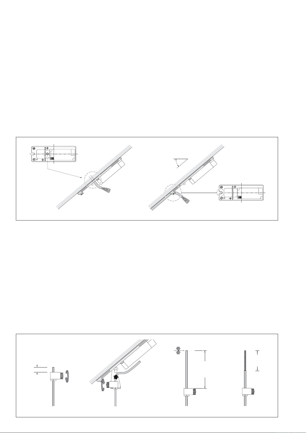
WICHTIG: Pendelleuchte während
der Einstellung der gewünschten
Abhängehöhe unbedingt festhalten!
Zur Feineinstellung der Abhängehöhe,
Rändelmutter lösen, Leitungslänge justieren
und Rändelmutter wieder festdrehen.
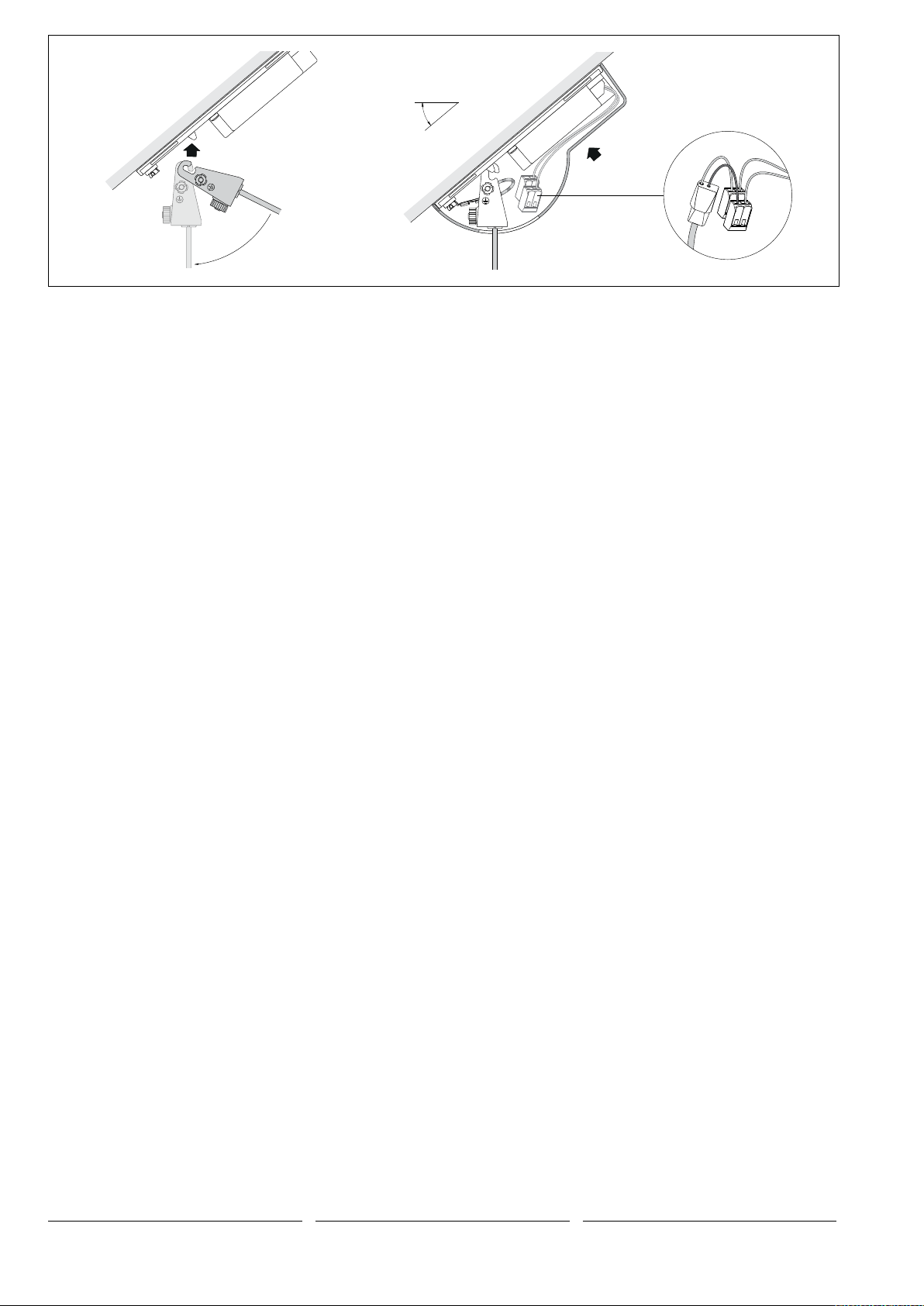
Nach Feineinstellung der Abhängehöhe,
Leuchtenaufhänger aus Montageplatte
aushängen und Pendelleuchte vorsichtig
ablegen.
Zugentlaster wieder aus dem
Leuchtenaufhänger ausklipsen.
Überschüssige Leuchtenleitung soweit kürzen,
dass oberhalb des Zugentlasters ein Überstand
von 120-130mm verbleibt.
Leuchtenleitung am oberen Ende 60mm bis
max.80mm abmanteln.
IMPORTANT: Ensure the pendant luminaire
is held rmly in place when setting the
desired suspension height!
To ne tune the suspension height, loosen the
knurled nut, adjust the cable length and tighten
the knurled nut again.
Once the correct suspension height is adjusted,
unhook the luminaire hanger from the mounting
plate and carefully place the pendant luminaire
onto a safe surface.
Remove the strain reliever from the luminaire
hanger.
Shorten the excess luminaire cable so that a
projection of 120-130mm remains above the
strain reliever.
Strip 60mm to max. 80mm of the insulation
from the luminaire cable at the top end.
IMPORTANT: Bien tenir le luminaire
fermement pendant le réglage de la
hauteur souhaitée de la suspension!
Pour un réglage précis de la hauteur de
suspension, desserrer l’écrou moleté, ajuster la
longueur de câble et resserrer l’écrou moleté.
Après le réglage précis de la hauteur de
suspension, décrocher l’attache du luminaire
de la platine de montage et déposer la
suspension avec précaution.
Déclipser de nouveau la décharge de traction
de l’attache du luminaire.
Raccourcir le câble du luminaire excédentaire
de manière à ce qu’il reste une longueur de
120-130mm au-dessus de la décharge de
traction.
Dénuder l’extrémité supérieure du câble du
luminaire de 60mm à 80mm maximum.
7- 87- 8
A B C D E
60-80 mm60-80 mm
Montage Koaxial-Leitungsverbinder
Leitungsverbinder auseinanderschrauben.
Abgemantelte Leitung(A) bis Anschlag in das
Verbinderunterteil (Klemmteil) einführen(B).
Leuchtenleitung unterhalb des
Verbinderunterteils festhalten.
Koaxialgeecht des abgemantelten Bereichs
mit zwei Fingern der anderen Hand unmittelbar
oberhalb des Verbindergewindes schrittweise
und vorsichtig zusammenschieben bis die
schwarze Ader freigelegt ist.
Achten Sie darauf, dass das
zusammengeschobene Koaxialgeecht in die
Vertiefung des Verbinderunterteil eingeführt ist –
siehe Skizze (C).
Schwarze Ader durch das zentrale Loch der
Schraubverschlusskappe führen.
Darauf achten, dass dabei die rote Ader
mit innenliegender Druckfeder richtig in der
Kappe positioniert ist. Verschlusskappe
(Verbinderoberteil) durch Rechtsdrehung mit
dem Klemmteil (Verbinderunterteil) bis Anschlag
verschrauben (D).
Schwarze Ader 7-8mm absetzen(E).
Installing the coaxial cable connector
Unscrew the line connector.
Guide the stripped cable end(A) into the lower
part of the connector (clamp part)(B) until it
stops.
Hold the luminaire cable below the lower part of
the connector.
Carefully push together the coaxial mesh of the
stripped section with two ngers of your other
hand bit by bit directly above the connector
thread, until the black wire is laid bare.
Make sure that the coaxial mesh is inserted into
the recess on the lower part of the connector –
see diagram (C).
Guide the black wire through the opening in the
middle of the screw cap.
Make sure that the red wire is correctly
positioned in the cap with the internal pressure
spring. Screw the closing cap (top part of the
connector) in clock-wise direction onto the
clamp part (lower part of the connector) until it
stops (D).
Strip back 7–8mm of the black wire(E).
Installation du connecteur coaxial
Démonter le connecteur.
Insérer le câble dénudé(A) dans la partie
inférieure du connecteur (pièce de serrage)
jusqu’à la butée(B).
Bien tenir le câble du luminaire sous la partie
inférieure du connecteur.
Faire glisser peu à peu et avec précaution le
maillage coaxial de la partie dénudée avec
deux doigts de l’autre main directement au-
dessus du letage du connecteur jusqu’à ce
que le l noir soit libre.
Vérier que le maillage coaxial rétracté soit
introduit dans le renfoncement de la partie
inférieure du connecteur. Voir schéma (C).
Insérer le l noir à travers le trou central du
capuchon leté.
Veiller à ce que le l rouge avec ressort de
pression intérieur soit correctement positionné
dans le capuchon. Visser le capuchon de
fermeture (partie supérieure du connecteur)
en le tournant vers la droite avec la pièce de
serrage (partie inférieure du connecteur) jusqu’à
la butée (D).
Dénuder le l noir de 7-8mm(E).
Zugentlaster in die Aussparung des
Leuchtenaufhängers einklipsen. Pendelleuchte
an der Leuchtenleitung aufnehmen und
Leuchtenaufhänger in Montageplatte
einhängen.
Clip the strain reliever into the recess on the
luminaire hanger. Lift the pendant luminaire
by the luminaire cable and hook the luminaire
hanger into the mounting plate.
Clipser la décharge de traction dans
l’évidement de l’attache du luminaire. Tenir
le luminaire par le câble de suspension et
accrocher l’attache du luminaire dans la platine
de montage.

BEGA Gantenbrink-Leuchten KG · Postfach 31 60 · 58689 Menden · info@bega.com · www.bega.com
4/4
0 - 40°
Schutzleiterverbindung zwischen
Leuchtenaufhänger und Montageplatte
(Steckverbindung) herstellen.
Anschlussader rot auf „+“ und Anschlussader
schwarz auf „-“auf den gekennzeichneten
Klemmen vornehmen.
Baldachin an die Decke schieben, passgenau
über die Montageplatte führen und mit leichtem
Druck einrasten lassen.
Establish the earth conductor connection
between the luminaire hanger and the
mounting plate (plug connector).
Make connection red wire to “+” and
connection black wire to “-” to the marked
terminals.
Push the canopy against the ceiling, making
sure it sits exactly over the mounting plate and
click it into place carefully.
Procéder à la mise à la terre entre l’attache du
luminaire et la platine de montage pour xation
(connecteur à che).
Procéder au raccordement des conducteurs au
bloc d'alimentation, l rouge à « + » et l noir à
«- » aux borniers marqués.
Faire glisser le cache-piton vers le plafond,
le guider exactement au-dessus de la platine
de montage et l’encliqueter en pressant
légèrement.
Ersatzteile
LED-Netzteil DEV-0342/350
Zugentlastung 75 004 118
Leitungsverbinder 75 004 119
Spares
LED power supply unit DEV-0342/350
Strain relief 75 004 118
Cable connector 75 004 119
Pièces de rechange
Bloc d’alimentation LED DEV-0342/350
Décharge de traction 75 004 118
Connecteur 75 004 119
Popular Tent manuals by other brands

Rubicon Expedition Products
Rubicon Expedition Products Hitch Tent manual

tropitone
tropitone Basta Sole Cabana Assembly manual

Atleisure
Atleisure GAZ-902220 Assembly and user's manual

Ventura
Ventura Marlin Assembly instructions

Corradi
Corradi PERGOTENDA MAESTRO user manual

Gorilla
Gorilla 10x10 Grow Tent instructions

Coleman
Coleman 2000007825 Setup instructions

White Duck Outdoors
White Duck Outdoors Alpha Wall Tent Series owner's manual

Bestway
Bestway 68092 owner's manual

Eureka
Eureka High Camp Assembly instructions

Johnson Outdoors
Johnson Outdoors Eureka! MIDORI 3 Assembly instructions

Palram
Palram Feria HG9310 Assembly instructions