Behler-Young VP2 Instruction manual

Model VP2
High/Low Burner/Control Box
with 20 - 70 ft Tube/Reflector Length
Form I-VP2 (Version A)
INSTALLATION / OPERATION / MAINTENANCE
Applies to: Model VP2 120V 60Hz
Gas-Fired, Tubular, Radiant,
Low-Intensity Infrared Heater
Part No. 270684

2
and servicing is undertaken on radiant tube
heaters specified in these instructions, due care
and attention is required to ensure that working
at height regulations are adhered to
PLEASE READ this document prior to
installation to familiarize yourself with the
components and tools you require at the various
stages of assembly.
All Dimensions shown are in inches unless
otherwise stated.
The manufacturer reserves the right to alter
specifications without prior notice.
Welcome to the new range of powered HiLo
infra-red heaters. Local regulations may vary
and it is the installer’s responsibility to ensure
that such regulations are satisfied.
All installation, assembly, commissioning and
service procedures must be carried out by
suitable qualified competent persons and
conform with local building codes, or in the
absence of local codes, with the National Fuel
Gas Code ANSI Z223.1/NFPA 54 or the
National Gas and Propane Installation Code
CSA B149.1.
When assembling, installing, commissioning
codes, with the National Fuel Gas Code,
ANSI Z223.1/NFPA 54 or the Natural Gas
and Propane Installation Code, CSA
B149.1.
D. The unit shall be electrically grounded in
accordance with National Electric Code
ANSI/NFPA 70 and Canadian Electrical
Code CSA C22.1.
E. The heater may be installed in aircraft
hangars in accordance with the Standard
for Aircraft Hangars, ANSI/NFPA 409 and
in automotive garages when installed in
1.1 Health and Safety
A. Heater is intended for heating
non-residential indoor spaces and should
only be installed where flammable gases
or vapors are not generally present.
B. Heaters may be suspended either
horizontal or at any angle. See section
1.3 for clearance dimensions.
C. The installation must conform with local
building codes or, in the absence of local
1 Installation Requirements
1.1 Health & Safety
1.2 Heater Suspension
1.3 Clearance to Combustibles
1.4 Gas Connection & Supply Details
1.5 Electrical Connections
1.6 Ventilation Requirements
1.6.1 Unvented Units
1.6.2 Vertical Venting
1.6.3 Horizontal Venting
1.7 Fresh Air Intake
1.8 Technical Details
2 Assembly Instructions
2.1 Tools Required
2.2 Assembly Notes
2.2.1 Tubes
2.2.2 Turbulators
2.2.3 Brackets
2.2.4 Couplers
2.2.5 Reflectors
2.2.6 End Caps (optional)
2.2.7 Bends (where required)
2.2.8 Burner/Fan Assembly
2.2.9 Heating Configurations
2.2.10 Detailed Assembly Drawings
3 Start Up Instructions
3.1 Tools Required
3.2 Start up procedure
4 Servicing Instructions
4.1 Tools Required
4.2 Burner Description
4.3 Burner Removal
4.4 Burner Gas Injector Servicing
4.5 Burner Head and Electrode Servicing
4.6 Combustion Fan Assembly
4.7 Radiant Tube Servicing
4.8 Reflector Servicing
4.9 Cleaning of Vent
4.10 Re-commissioning after Service
5 Spare Parts
6 Troubleshooting Guide
7 Replacing Parts
7.1 Burner Controller Replacement
7.2 Air Pressure Switch Replacement
7.3 Gas Valve Replacement
7.4 Optional Extra Kits
8 User and Operating Instructions
8.1 To Start Heater
8.2 To Switch Off Heater
8.3 Servicing
Introduction.
Document Index.
1. Installation Requirements.
3
accordance with the Standard for Park-
ing Structures, ANSI/NFPA 88A, or the
Standard for Repair Garages, ANSI/
NFPA 88B, or the Canadian Natural
Gas and Propane Installation Code,
CSA B149.1, and are so marked.
Ensure that minimum clearances will be
maintained to vehicles parked below the
heater.
F. The standard heaters are approved for
installations between 0 - 2000ft (0 -
610m) for the US and 0 - 4500 ft
(1370m) for Canada. Conversion kits are
available for installations above these
heights in the USA.
Note: Any outdoor installations must be in-
stalled with a vent cap at the inlet and the flue
end.
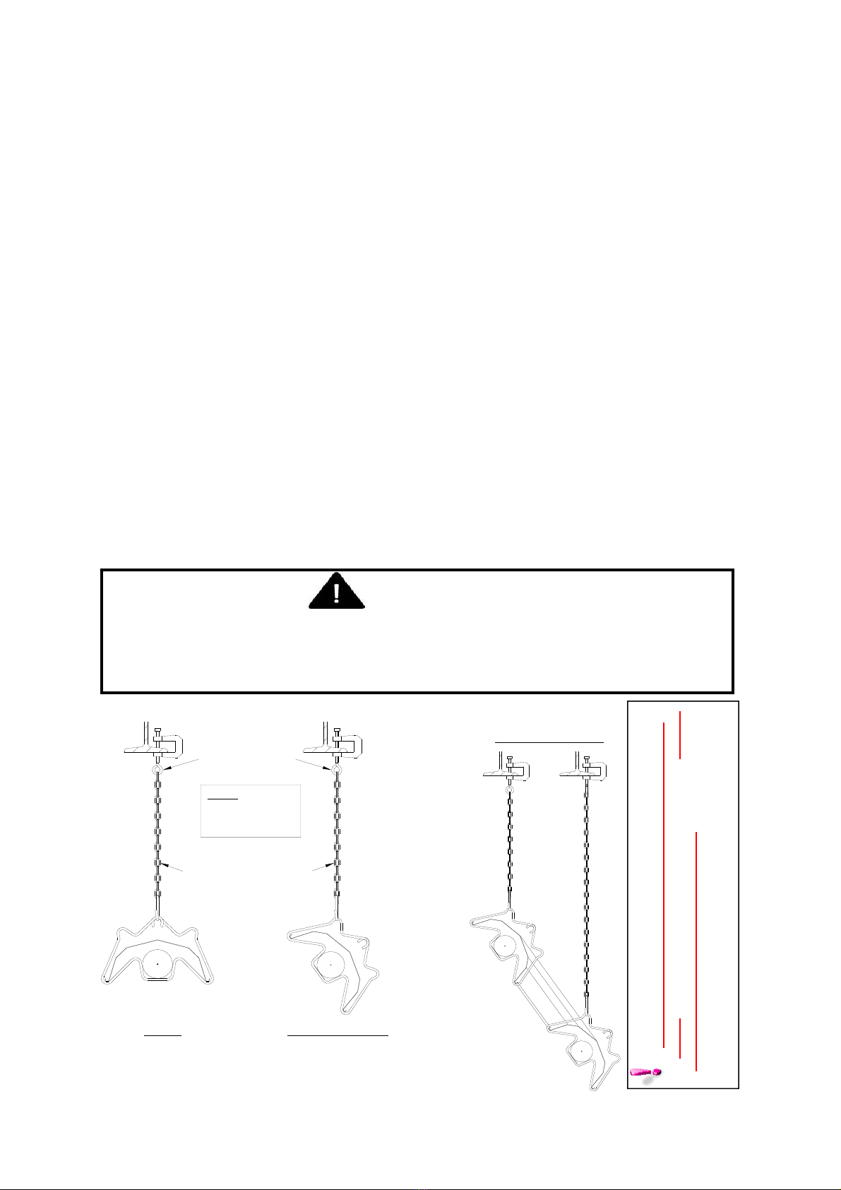
1.2 Heater Suspension
Attachment to the heater support lugs should
be made by D shackle. The hanging attach-
ments to overhead steelwork etc. must be pur-
pose made to sound engineering practice or
supplied to others. They must be adequately
fixed and designed to carry the whole weight of
the heater. In the event of suitable roof
steelwork being unavailable, additional steel-
work should be fitted to enable vertical hangers
to be used for suspending the heaters.
These methods are illustrated in Figure 1. If
there are any doubts as to the strength or
suitability of roof steelwork to which heaters are
to be suspended, please refer to a Consultant,
Architect or owner of the building.
It is recommended that the heater is raised to its
final position once the assembly of the tube/
bracket/reflector has been completed. Longer
tube assemblies may be raised in more than
one sub-assembly with final tube connection
made in the air.
Ensure that the installer uses the burner roof
support mounting bracket when suspending the
heater. This is situated on the front of the
burner. When packed the bracket is reversed
and must be turned to its correct state for
mounting. (ref page 15)
Figure 1. Recommended Methods of Heater Suspension.
ON U TUBE VARIANTS THE HEATER SHOULD
SLOPE DOWNWARDS TOWARDS THE RETURN
BEND AND ON LINEAR VARIANTS SHOULD SLOPE
DOWNWARDS TOWARDS BURNER BY APPROX. ½”
FOR HORIZONTAL INSTALLATIONS
WARNING:
If not installed, operated and maintained in accordance with the manufacturer’s instruc-
tions, this product could expose you to substances in fuel or from fuel combustion which
are known to the state of California to cause cancer, birth defects or other reproductive
harm.
CHAIN 55° SUSPENSION
2/0 GA CHAIN
(TWISTED LINK, PLATED)
NOTE.
HOOKS ARE TO
BE CLOSED UP
AFTER ASSEMBLY
EYE HOOKS
EXHAUST
END
BURNER
END
U TUBE VARIANTS
Suitable Chain Working
Load Limit 100lb.
4
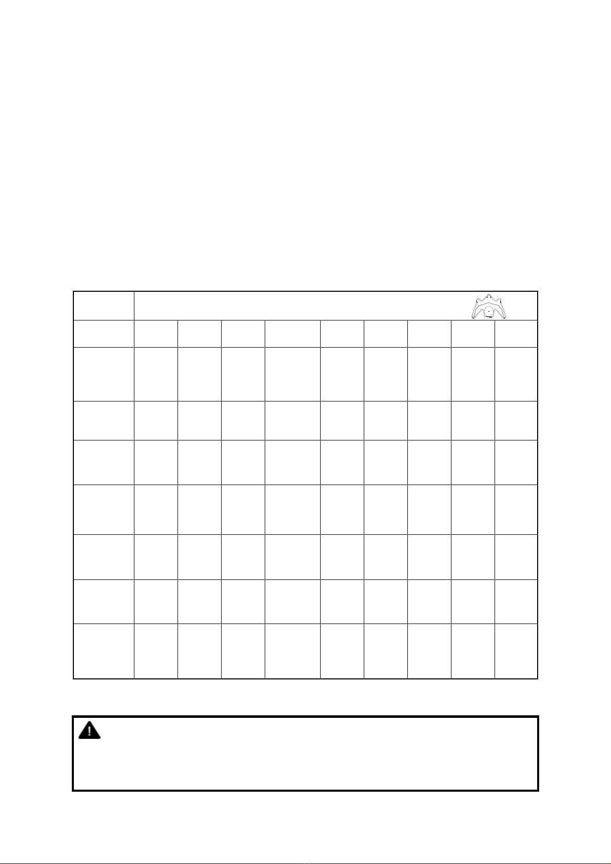
1.3 Clearance to Combustibles.
Minimum clearance to combustibles are shown
in Table 1 below.
IMPORTANT:
The stated clearance to combustibles
represents a surface temperature of 90°F (50°C)
above room temperature. Building material with
a low heat tolerance (such as plastics, vinyl
siding, canvas, tri-ply, etc.) may be subject to
degradation at lower temperatures.
It is the installer’s responsibility to assure that
adjacent material are protected from
degradation.
* distance with end caps fitted.
Table 1 Clearance to Combustibles, inches (cm)
Model A B B1 C1 C2 C3 D1 D2 E
18 74 (188) 29 (74) 41 (105) 6(16) / 3(8)* 8 (21) 22 (56) 8 (21) 14 (36) 10 (26)
25 74 (188) 29 (74) 41 (105) 6(16) / 3(8)* 8 (21) 22 (56) 8 (21) 14 (36) 10 (26)
30 74 (188) 32 (82) 41 (105) 6(16) / 3(8)* 8 (21) 22 (56) 8 (21) 16 (41) 10 (26)
38 74 (188) 39 (99) 47 (120) 6(16) / 3(8)* 8 (21) 22 (56) 20 (51) 18 (46) 10 (26)
45 74 (188) 39 (99) 48 (122) 6(16) / 3(8)* 8 (21) 22 (56) 20 (51) 18 (46) 10 (26)
50 86 (219) 48 (122) 48 (122) 6(16) / 3(8)* 11 (28) 22 (56) 20 (51) 20 (51) 10 (26)
60 86 (219) 48 (122) 48 (122) 6(16) / 3(8)* 11 (28) 22 (56) 20 (51) 20 (51) 10 (26)
Minimum clearance from the heater must be maintained from vehicles
parked below heater. In all situations, clearances to combustibles must be
maintained. Signs should be posted in storage areas to specify maximum stacking height to
maintain required clearance to combustibles. Such signs must either be posted adjacent to
the heater thermostats or in the absence of such thermostats in a conspicuous location.
Refer to mounting clearance tables.
WARNING:

5
Figure 2 Clearance to Combustibles (Standard indoor reflectors).
The minimum clearances to combustible materials are given in the tables below. These
minimum distances MUST be adhered to at all times. Adequate clearance MUST be provided
around air openings into the combustion chamber and there MUST be suitable clearance for
accessibility and for combustion / ventilating air supplies.
C2
C1
A
B1
B
B
A
E
D2
0° to 55°
D1
Ensure that there is adequate
provision in the building for
combustion and ventilation air
supply. Installation must meet
minimum requirements and
appliciable codes.
Burner end.
Outlet end.
Angled view.
End view.
C3
Below
heater
Side
vented
Side
unvented
End
unvented
Above outlet
unvented
Above
Reflector
Above
Burner
Service
distance
Return end on
U tube heater
Ensure that there is adequate
provision in the building for
combustion and ventilation air
supply. Installation must meet
minimum requirements and
appliciable codes.
WARNING!
applicable

6
1.4 Gas Connection and Supply
The gas connection on the heater is ½” N.P.T
internal thread.
Injector sizes and manifold pressure for the
burners are shown in the table 3. The gas
supply piping and connections must be installed
so that the minimum pressure stated is
achieved.
A gas shut off valve and union should be fitted
in the gas supply line close to the heater and a
⅛” N.P.T plugged tapping, accessible for test
gauge connection, provided immediately
upstream of the appliance gas inlet.
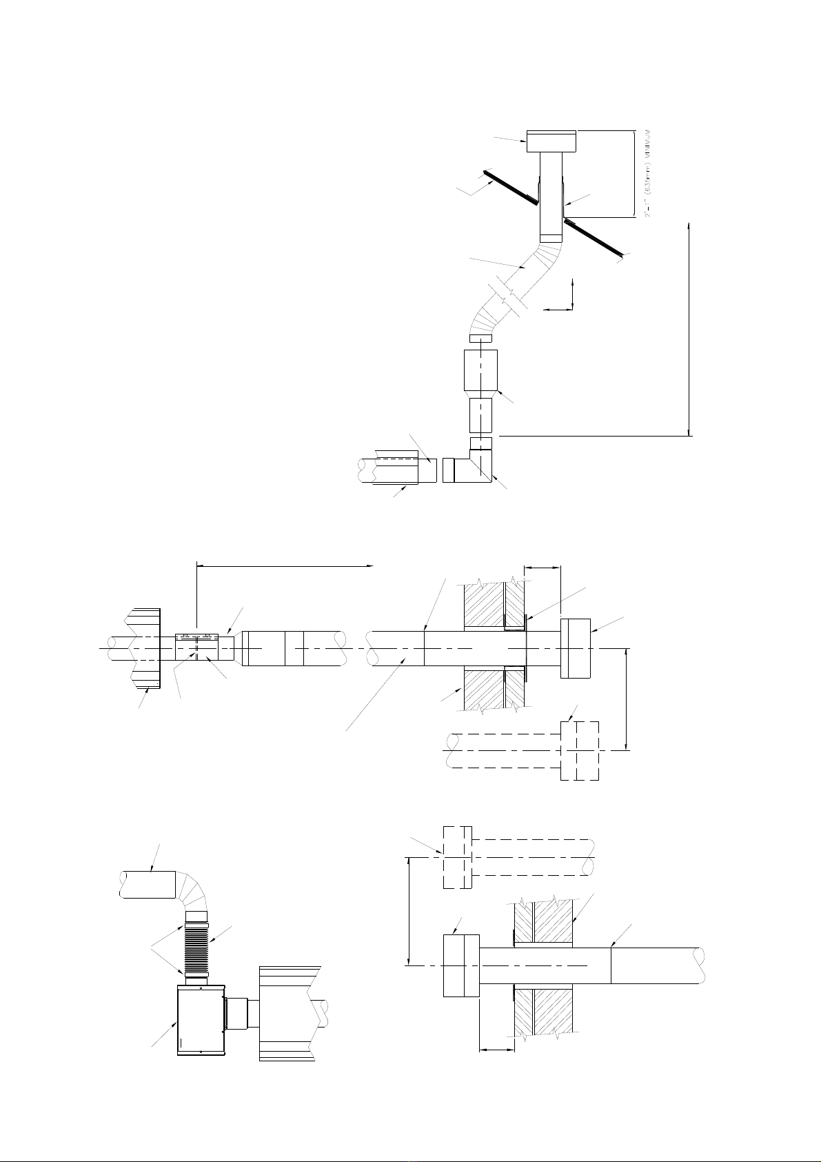
It is essential to provide some flexibility in the
final gas connection by use of an approved
flexible gas connector. (See Fig 4.)
Take care when making a gas connection
to the heater not to apply excessive turning
force to the internal controls.
Care must be taken to observe the minimum
pipe bend diameter (minimum 10” (254mm),
maximum 14”(356mm) & pipe expansion
distance (minimum 1⅛” (25.4mm), maximum
3¾”(95mm).
The correct installation as shown will allow
for approx 4” of movement due to expansion.
WARNING: Before installation, check
that the local distribution conditions,
nature of gas and pressure, and adjustment
of the appliance are compatible.
Figure 3. Correct orientation of Ball Valve
Gas Flow
Gas Flow
Figure 4. Correct Installation of Flexible
Gas Connection
* Connector must be certified for use on a radiant tube type
infrared heater and must comply with Standard for
Connectors for Gas Appliances, ANSI Z21.24/CSA 6.10 or
with the Standard for Elastomeric Composite Hose and
Hose Couplings for Conducting Propane and Natural Gas,
CAN/CGA 8.1.
For heaters up to 150,000Btu/h, ½” ID x 24” long
For heaters above 150,000Btu/h and above, ¾” ID x 36”
long
NOTE: For Canada all heaters MUST use a hose 36” long
See Table 2
HOSE
SIZE
USA CANADA
3/4” CE4 CONTACT
FACTORY
Table 2
WARNING: FIRE OR EXPLOSION HAZARD - Expansion of the radiant pipe occurs with
each firing cycle causing the burner to move with respect to the gas line. This can
result in a gas leak producing an unsafe condition. It is therefore essential to provide some
flexibility in the final gas line connection by use of an approved flexible connector as shown
in the drawings.

7
1.5 Electrical Connections
This appliance must be electrically grounded
Supply 120V 60Hz single phase.
Standard heater 0.16HP.
Current rating 1.2 amp max (inductive).
Fuse: external 3 amp.
Important: All electrical work should be done by a
qualified electrician in strict accordance with the
National Electrical Code ANSI/NFPA 70 or
Canadian Codes CSA C22.1.
The electrical supply to
the heater is by three
wires: hot (Live), neutral
and ground connections.
Install in accordance with
all state & local codes.
Where alternative manu-
facturers controls are
used, please refer to their
instructions for their
installation details.
Table 3 Gas Supply Pressures
WARNING: Before making electrical
connections, switch OFF the main
electrical disconnect. There may be more
than one disconnect switch. Lock out
and tag switch with a suitable warning
label. Electrical shock can cause
personal injury or death.
Figure 5. External Wiring Schematic.
Notes:
Use 18/4 class 2 thermostat cable between
heater(s) and thermostat.
Max. length @ 18 Awg (0.8mm²) = 100ft.
No more than 2 burners can operate from one
thermostat as supplied.
However, a control is available from the
manufacturer that allows up to 8 burners to be
operated from one thermostat as a single zone.
F2
F1
R
C
W1
W2
24V AC
Terminals
(120V AC Fan
Terminals)
120V AC
Supply
24V AC 2-Stage
Thermostat (Ext.)
RC
W1 W2
F2
E
N
F1
L
N
E
R
C
W1
W2
24V AC
Terminals
(120V AC Fan
Terminals)
120V AC
Supply
Burner 1 Burner 2
E
N
L
N
E
CONNECTOR MUST BE INSTALLED IN A “U” CONFIGURATION. FOR HEATERS
UPTO 150,000 BTU/H, A 24” LONG CONNECTOR OF AT LEAST ½” ID MUST BE
USED. FOR HEATERS ABOVE 150,000 BTU/H, A 36” LONG CONNECTOR OF AT
LEAST ¾” NOMINAL ID MUST BE USED.
KEY:
BK-BLACK
BL-BLUE
R-RED
O-ORANGE
G-GREEN
W-WHITE
BL
BK
R
O
BK
BK
G G
W W
Gas Type Natural Gas LP/Propane Gas
Required Gas Pressure (in W.C) (60,000 TO 150,000
BTU) 5.0 11.0
Required Gas Pressure (in W.C) (170,000 TO
200,000 BTU) 7.0 11.0
Max Supply Pressure (in W.C) 14.0 14.0
Gas Supply Connection ½” N.P.T thread

8
If any of the original wire as supplied with the appliance must be replaced, it must be replaced
with wiring material having a temperature rating of at least 220°F/105°C
When servicing heaters ensure the electricity
supply is isolated from the mains supply.
120V AC supply is still present at each burner
when the thermostat is switched off.
Figure 6a. Internal Burner Wiring Diagram.
LN
E
L1
Gas Control
MV
X
C
COM
W1
PS0
PS1
IND
R
E
Gas Valve
C
M
HI
NOTES:-
Power On light is permanently illum inated w hen 120V / 60 H z A C external supply is connected to burner.
Additional wiring is required to install a thermostat and / or time clock.
Wire specification:- 18 AW G (1.0mm²), Tri-rated, 105°C
Pressure Switch
120V/24VAC 60Hz
Transformer
Power ON (red)
BK
R
Y
O
BR
GR
BL
KEY:
BL - BLUE
BK - BLACK
BR - BROWN
GR - GREY
G - GREEN
K - PINK
R - RED
W - WHITE
Y - YELLOW
O - ORANGE
P - PURPLE
BR
Y
P
YY
R
W
G
BK
W
G
BL BR
PGR
P
GR
K
BR
W
BK
LNE
120V AC
Supply
BK
F1 NEF2
120V AC Fan
Terminals
High Fire
KGR
24V AC
RELAY
21
1424
11
A2
1222
A1
High Fire
Relay
COIL
NC
NO
COM
CW2W1
R
24V AC Stat
Terminals
K
O
BL
BR
Low Fire
(am b er)
CW2W1
R
24V Two stage
Thermostat
R
W
G
BK
W
G
BK
BL
R
BK
R
K
O
BL
BR
E

9
1.6 Vent Requirements and Details
1.6.1 Unvented units
Heaters may be installed without a vent
providing the governing building codes are met
and consideration is properly given to
possibilities of condensation on cold surfaces.
Installation shall meet the following
requirements when unvented:
Internal volume of the heated room must
be greater than 214cu.ft. per 100 BTU
per hour of heaters installed.
OR
Natural or mechanical means shall be
provided to supply and exhaust at least 4
CFM per 1000 BTU per hour input of
installed heaters.
Combustion gasses shall not impinge on
combustible materials.
1.6.2 Vertical venting
The heater can be installed with a vertical vent.
All vent piping should be adequately supported
from the building structure and terminated with
an approved terminal. The maximum
recommended vent length is 25ft (7.6m) with
a maximum of two elbows. All connections
should be properly sealed. (refer fig 7a)
1.6.3 Horizontal venting
Individual units can be vented horizontally
through side walls. Recommended terminals
are part numbers 111848 for 4” and 111850 for
6”.
Distances from adjacent public walkways,
adjacent buildings, openable windows and
building openings, consistent with the National
Fuel Gas Code, ANSI Z223.1/NFPA 54 or the
Natural Gas and Propane Installation Code,
CSA B149.1.
Maximum length of vent is 25ft (7.6m) with two -
90° elbows.
Runs of 12ft (3.6m) or shorter can use
4” (101mm) diameter vent. Runs over 12ft
(3.6m) should use 6” (152mm) vent pipe.
Any portion of vent that passes through a
combustible wall must be insulated, or use an
approved insulating thimble.
Standard vent terminals must extend at least
6” (152mm) from the wall and at least
24” (609mm) from any combustible overhang.
Protect the building material from degradation
by the vent gasses.
Vent joints should be sealed and secured
according to the vent manufactures installation.
Should condensation occur the vent should be
shortened or insulated.
The terminal should be at least 3ft (0.91m) away
from any air intake to the building.
If the heater is equipped with ducted combustion
air, the vent terminal must be at least 3ft
(0.91m) away from the air inlet and located
higher than the inlet.
The vent terminal must be installed at a suitable
height above the ground to prevent blockage by
snow.
1.7 Fresh Air Intake
Whenever the heater is installed in locations
where airborne dust or other pollutants are
present, a fresh air supply should be ducted to
the burner.
A fresh air duct of 4” (101mm) diameter should
be installed from the fresh air to the air intake
connection on the burner housing. A flexible
Other burners
KEY:
G-GREEN
W-WHITE
BK-BLACK
R-RED
G
R
BK
W
Supply circuit
120V 60Hz 1 Ph
S-0700
C
30VA
Trans
Relay
L1
G
R
L2 L2
L1 (HOT)
GND
T
24V Thermostat
other burners
Burner 1
RW1
C
Fan center relay
(Suppled by others)
W
BK
BK
G
BK
Figure 6b. Multiple Heater Installations 24V Control
10
jointing piece should be installed at
the burner connection with hose
clamps to facilitate expansion and
contraction.
The maximum recommended length
air duct is 25ft (7.6m) and the
maximum number of bends is two.
The minimum length is 18” (456mm).
The location of the fresh air duct
inlet must be where it will receive
dust free clean air. An inlet cap with
bird screen must be fitted at the inlet
of the duct. If the duct inlet is located
above the roof the underside of the
inlet terminal must be at least 2ft
(0.61m) above roof level and at least
10” (254mm) above any projection
on the roof within 7ft (2.1m) of the
inlet. Intake pipe, fittings and
sealant are not furnished by the
manufacturer. (Refer fig 7c & 7d.)
Figure 7.a Vertical Venting.
Figure 7.b Horizontal Venting.
Figure 7.c Fresh Air Ducted Intake. Figure 7.d Wall Terminal Intake Kit.
REFLECTOR
END OF RADIANT TUBE
VENT ADAPTOR ELBOW
12'-0" (3.66m)
12'-0" (3.66m)
(APPROXIMATE
MAXIMUM DIMENSIONS)
CODE APPROVED VENT
THROUGH ROOF
SEAL
SUPPLIED BY OTHERS
ROOF
4" (101mm) O.D. OR
HIGH TEMPERATURE SILICONE
SEAL JOINTS WITH
REQUIRED ONLY FOR 6" (152mm) DIA. VENT
4" (101mm) TO 6" (152mm) DIA. ALUMINUM ADAPTER
6" (152mm) O.D. FLUE
ALUMINUM
RADIANT
TUBE
REFLECTOR
4" (101mm) TO 6" (152mm) DIA. ALUMINUM ADAPTER
TERMINAL
6" (152mm)
COLLAR
SEAL JOINTS WITH
HIGH TEMPERATURE
WALL
REQUIRED ONLY FOR 6" (152mm) DIA. VENTS
ALUMINUM 4" (101mm) O.D. MAXIMUM LENGTH = 12'-0" (3.66m)
ALUMINUM 6" (152mm) O.D.MAXIMUM LENGTH = 25'-0" (7.62m)
(PLUS A MAXIMUM OF 2 x 90° BENDS
END OF
SUPPLIED BY OTHERS
COUPLER
SILICONE
INLET WITH
BIRD SCREEN
36" (914mm) MIN CENTERS
NOTE: The vent
terminal should be
installed so as to be in
the same atmospheric
pressure zone as the
combustion air inlet of
the appliance
INLET WITH
6" (152mm)
SEAL JOINTS WITH
SILICONE OR DUCT TAPE
WALL
BIRD SCREEN
TERMINAL
36" (914mm) MIN CENTERS
CLAMPS
BURNER
4" (106mm) O.D. FLEXIBLE DUCT
ALUMINUM 4" (101mm) O.D. PIPE
MAX LENGTH = 25'-0" (7.62m) WITH 2-90° LONG RADI US BENDS
4.25” (108mm) O.D FLEXIBLE DUCT
ENSURE ALL JOINTS ARE
SEALED
APPROVED CAT III VENT PIPE
APPROVED CAT 3 VENT PIPE
VENT CAT III ELBOW
ELBOWS
CAT III ADAPTER
WITH TWO-90° ELBOW

11
1.8 Technical Details - Table 4
No of Injectors 1
Gas Connection ½” N.P.T
Electrical Supply 120 volt 1 phase 60Hz
Vent size (in) 4” or 6” (101mm or 152mm)
Unitary Fan Motor Details 120 volt 1 phase 60Hz
Current Rating 1.2A MAX
Ignition Electronic Program Start up with Spark Ignition
Thermostat 24Vac 60Hz 1.5A Max. total load
Burner
Size
Natural Gas LP Gas Min. Heater
Length
Max. Heater
Length
Min. Heater
Length
Max. Heater
Length
High / Low
Rate BTU/Hr
High / Low
Rate BTU/Hr S ft (m) S ft (m) U (ft) U (ft)
18 60,000/45,000 60,000/45,000 20 (6.1) 40 (12.1) 20 (6.1) 40 (12.1)
25 80,000/60,000 80,000/60,000 30 (9.1) 40 (12.1) 40 (12.1) 40 (12.1)
30 100,000/65,000 100,000/65,000 30 (9.1) 40 (12.1) 40 (12.1) 40 (12.1)
38 123,500/95,000 125,000/95,000 30 (9.1) 50 (15.2) 40 (12.1) 40 (12.1)
45 150,000/100,000 150,000/100,000 40 (12.1) 60 (18.3) 40 (12.1) 60 (18.3)
50 169,000/125,000 169,000/125,000 50 (15.2) 70 (21.3) 60 (18.3) 60 (18.3)
60 200,000/150,000 N/A 50 (15.2) 70 (21.3) 60 (18.3) 60 (18.3)
Burner
Size
Natural Gas 0-2000 ft (0-610m) LP Gas 0-2000 ft (0-610m)
Burner Orifice
Plate Injector Injector
Pressure
Burner Orifice
Plate Injector Injector
Pressure
Part No. Part No. Inches WC. Part No. Part No. Inches WC.
High Low High Low
18 269941 270400 4.2 2.4 269948 270398 6.1 3.5
25 269942 270402 3.9 2.3 269949 270399 5.2 3.0
30 269943 270403 4.9 2.1 269950 270399 8.2 3.7
38 269944 270405 4.5 2.7 266951 270400 7.6 4.4
45 269945 270407 4.4 2.2 266952 270401 7.2 3.3
50 269946 270409 4.0 2.4 266953 270403 6.8 3.9
60 269946 270410 4.6 2.8 N/A
CANADA
ONLY 10%
DERATE
Natural Gas 2001-4500 ft (611-1370m) LP Gas 2001-4500 ft (611-1370m)
Burner Orifice
Plate Injector Injector
Pressure
Burner Orifice
Plate Injector Injector
Pressure
Burner
Size Part No. Part No. Inches WC. Part No. Part No. Inches WC.
High Low High Low
18 269941 270400 4.1 2.3 269948 270398 6.0 3.4
25 269942 270402 3.7 2.1 269949 270399 5.0 2.9
30 269943 270403 4.7 2.0 269950 270399 8.0 3.5
38 269944 270405 4.3 2.5 269951 270400 7.4 4.2
45 269945 270407 4.2 2.0 269952 270401 7.0 3.1
50 269946 270409 3.8 2.2
60 269946 270410 4.4 2.6
ALTITUDE CONVERSION KITS ARE AVAILABLE
N/A

12
Options * Not available on LP Gas
1 All standard units fitted with unvented vent, natural gas and aluminized reflectors.
2 1 off 180° ‘U’ bend or upto 2 off 90° ‘L’bends can be fitted at no less than 50% of the total heater length.
3 5ft tube kit, 4” (101mm) or 6” (152mm) vent terminal.
4 Combustion air kit.
5 Reflector end caps.
6 Altitude conversion kit.
7 Propane and propane altitude conversion kit.
MODEL
U TUBE STRAIGHT TUBE
U20 U40 U60 S10 S20 S30 S40 S50 S60 S70
18 ●●●●●
25 ●●●
30 ●●●
38 ●●●●
45 ●●●●●
50 ●●●●
60 ●
●●●
Burner
Size
Natural Gas LP Gas All types
Combustion Fan
Details
Pressure
Switch
Combustion Fan
Details
Pressure
Switch
Burner
Head
Fan Type Orifice
Part No. Part No. Fan Type Orifice
Part No. Part No. Part No.
270464 270464
270425
18 269921
270386
269924
270386
25 269925 269925
30 269923 269928
38 269927 266931
45 269930 269933
50 270467 266935 270467 269936
60 269938 270387 N/A
MODEL
TUBE TYPE MATERIAL MIN DISTANCE
TO BEND
Calcoat™ Mild Steel
18 TUBE 1 REMAINDER 10 (3.1)
25 TUBE 1 REMAINDER 15 (4.6)
30 TUBE 1 REMAINDER 15 (4.6)
38 TUBE 1 REMAINDER 15 (4.6)
45 TUBE 1 REMAINDER 20 (6.1)
50 TUBE 1 & 2 REMAINDER 25 (7.6)
60* TUBE 1 & 2 REMAINDER 25 (7.6)
13
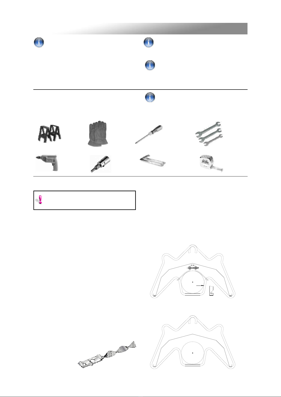
2.2.3 Brackets
There can be four types of brackets supplied
with these heaters:
2.2.3.1 Brackets for Indoor heaters
Type ‘H’ are suspension brackets with
tube straps.
Type ‘G’ are suspension brackets with
no tube straps.
2.2 Assembly Notes.
2.2.1 Tubes
Each heating unit has two types of emitter
tubes. For details of the tube types please refer
to the table (page 12 of this instruction
manual).
Identify and position tubes on saw horses. For
aesthetics it is advisable to position all tube
seams facing down. Position coupling
fastener so that these cannot be seen from
beneath the heater.
Mark out the position of the bracket centres
from the dimensions shown on the assemblers'
drawings.
Turbulators: Ensure that the correct
turbulator or burner insert is fitted, as this could
void your warranty if they are incorrectly fitted
or omitted when necessary.
2.2.2 Turbulators (where fitted)
Insert turbulator into correct
tube as indicated in the
assembly drawings
PLEASE READ this section prior to
assembly to familiarize yourself with the
components and tools you require at the
various stages of assembly. Carefully open the
packaging and check the contents against the
parts and check list.
The manufacturer reserves the right to alter
specifications without prior notice.
Please ensure that all packaging is
disposed of in a safe environmentally
friendly way.
For your own safety we recommend the
use of safety boots and leather faced
gloves when handling sharp or heavy items. The
use of protective eye wear is also
recommended.
Phillips
Screwdriver
Saw
Horses
Leather
Faced
Gloves
Tape
Measure
5/16”
Drive
Cordless
Drill
Wrench
Set
2.1 Tools Required.
The following tools and equipment are advisable
to complete the tasks laid out in this manual.
Suitable alternative tools may be used.
Please read these assembly notes in
conjunction with the correct assembly
drawings (figs 9 to 17).
"A"
VIEW ON "A"
3/16” (5mm)
5/32” (4mm)
Allen
wrench
2. Assembly Instructions.

14
Type ‘F’ are fixed reflector brackets.
Type ‘S’ are sliding reflector brackets.
Slip the suspension brackets onto the tube
assembly. The fixed suspension point ’H’
shown on the drawings are adjacent to the
burner and secures the first suspension bracket
to the tube with a tube strap. All other
suspension brackets ’G’ shown on the
drawings, have floating suspension points.
Reflectors are fixed at point ’F’ with a reflector
support bracket and reflectors are held in
position with fixing screws. Fixed and sliding
joints alternate along the heater at the
spacing's indicated on the individual heater
assembly sheets.
2 x SCREWS TIGHTENED TO FIX REFLECTOR
LEAVE 1/8" MIN. GAP TO ALLOW REFLECTOR TO SLIDE

15
2.2.5 Reflectors.
After removing the protective plastic coating
(if fitted), slip the reflectors through the hanger
brackets until they overlap each other.
The first and second reflector are fixed at the
point F by a type F reflector support bracket and
are held in place by tightening the fixing screws.
Alternate fixings of further reflectors by type S
and type F reflector brackets and space as
indicated by individual assembly sheets.
DO NOT OVERTIGHTEN.
Moving between the four bolts, tighten each
ensuring that equal pressure is applied to each
set pin in turn. Complete assembly by drilling
and screwing self tapping retention zip screws.
All reflectors must be positioned/
attached to the brackets exactly as
detailed in the assembly drawings.
Reflector support bracket assemblies are
fitted at each reflector joint, with the clamp
screws adjusted so that reflectors are
fixed together.
Each subsequent reflector must
OVERLAP the previous one as shown
below and to a distance as indicated by
their individual assembly sheets.
At this point raise the tube assembly into
position and suspend from previously
fixed chains (Working Load 100lb).
Longer tube assemblies may be raised in
more than one sub-assembly with final
tube connection made in the air. It is
recommended that the heater be
suspended to slope slightly down-ward
from the burner approximately 1” in 20
feet, but not more than 2” total overall.
2.2.4 Couplers
The couplers are used for joining radiant tubes
and L bends.
Slide the coupler over the tube ensuring that
the screw stop has butted up to the tube ends.
Using the 9/16” wrench to tighten the bolts.
HFSF
Burner
Assembly
Reflectors
2/0 GA CHAIN
(TWISTED LINK, PLATED)
NOTE.
HOOKS ARE TO
BE CLOSED UP
AFTER ASSEMBLY
EYE HOOK
16
2.2.10 Detailed Assembly Drawings
The pages following that show the technical
dimensional details of the range of heaters.
Please note the heater type, length and
reference number from the delivery/advice note
before identifying the correct model drawing.
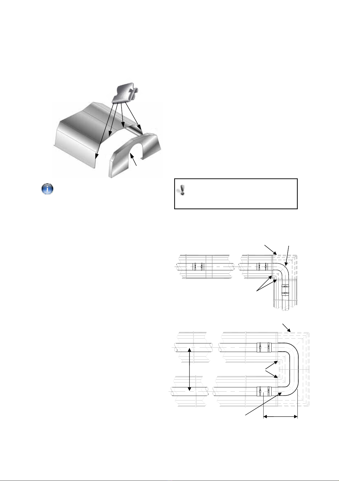
Typical usage of optional bend kits:
2.2.6 End Caps (optional)
Position an end cap beneath the reflector
profile (where required) with the end cap flanges
facing inwards. Fasten to reflector using the
four ’Z’ clips.
Note: For high wind/outdoor applications
use additional drill screws to secure end cap to
the reflector.
2.2.7 Bend(s) (where fitted)
The heater can be installed with 1 or 2 90° (L)
bends or a 180° U bend.
Slide the bend into the open end of the
coupler ensuring that the screw stop has butted
up to the tube ends. Refer to 2.2.4 for fastening.
2.2.8 Burner/Fan Assembly.
Slide the burner assembly onto the open tube
end, ensuring it is fully engaged. Secure with set
screws.
For the purpose of unvented applications, a 4”
90° elbow should be used on the terminating
end of the radiant tube sections. This elbow
should be turned with the outlet facing either
side.
Connect Gas and Electrical supplies as
described in sections 1.4 and 1.5.
2.2.9 Heater Configurations
The sketches shown on the following page show
various heater configurations for the model
series dependant on heater length and rating. It
is important not to configure a heater outside of
these recommendations.
Bends must be fitted at a distance of at
least 50% of the total heat exchanger
e.g. for a 60ft long heater, the closest to
the burner a bend can be is 30ft.
90° Bend
End Caps
Corner reflector
End Caps
16” crs
15”
U Bend
Corner reflectors (optional)
End Cap
90° Elbow
Corner reflectors kit

17
S20
S30
S40
S50
S60
S70
U20
U40
U60
Bends must be fitted at a distance of at
least 50% of the total heat exchanger
e.g. for a 60ft long heater, the closest to
the burner a bend can be is 30ft.
Figure . 8. Possible Heater Orientations
18
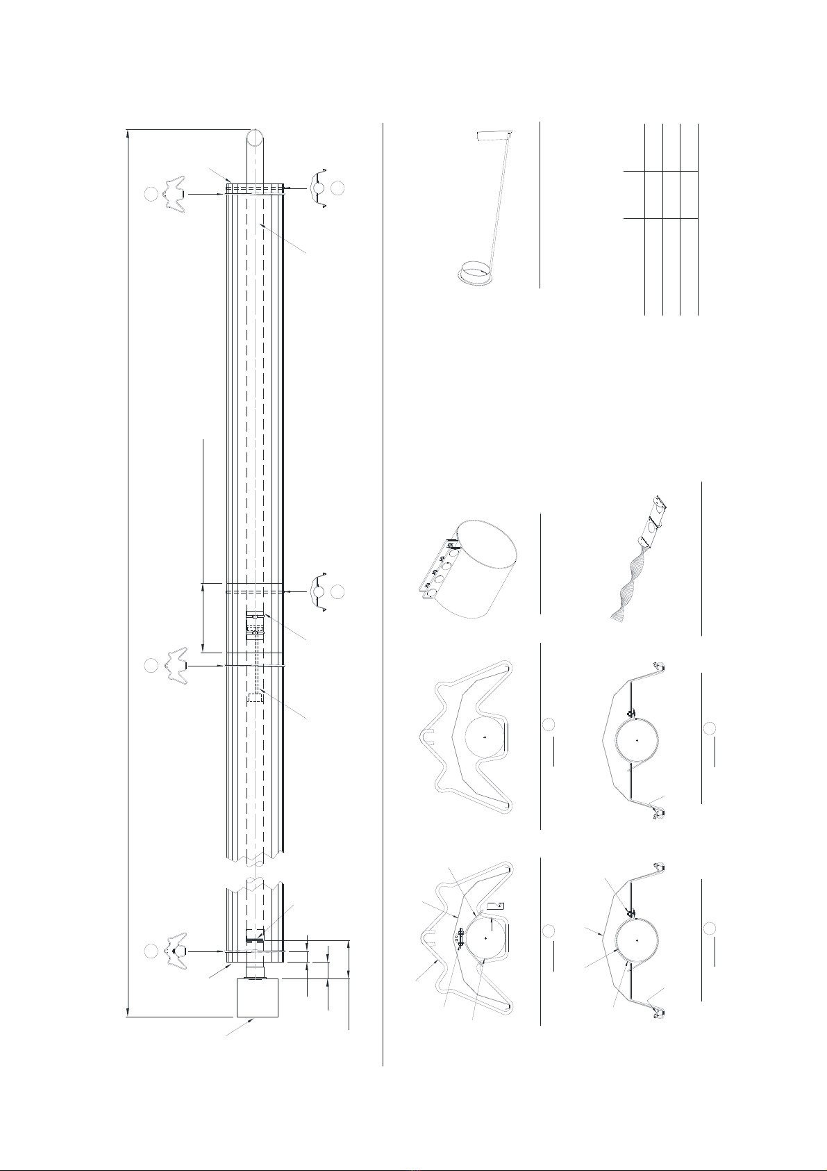
Figure 9. Heater Assembly: Model Linear 18-S20.
G
6"-9" REFLECTOR OVERLAP
F
GH
COUPLERS
BURNER
END
CAPS
(OPTIONAL)
10' 3" REFLECTORS TYPICAL OF 2
END
CAPS
(OPTIONAL)
BURNER INSERT
(SEE DETAIL)
MODEL 25
NAT GAS ONLY S
DISTANCE BETWEEN
SUSPENSION POINTS
NO TO EXCEED 12'
21'6½" NOMINAL OVERALL ASSEMBLED LENGTH
FIRST SUSPENSION POINT TUBE STRAP
DETAIL
TUBE & REFLECTOR SUSPENSION BRACKET
DETAIL
DETAIL
SLIDING REFLECTOR BRACKET
DETAIL
FIXED REFLECTOR BRACKET
REFLECTOR
TUBE
STRAP
RADIANT
TUBE
2 x SCREWS TIGHTEN TO
FIX REFLECTOR
2 x SCREWS MIN 1/8" GAP TO
ALLOW REFLECTOR TO SLIDE
SUPPLIED
NUT &
BOLT
C
L
2" MINIMUM
REFLECTOR OVERLAP BURNER INSERT DETAIL PT. NO. 270489
NOTE: FOR MODEL 80 NAT GAS ONLY
H G
SF
STANDARD 4" COUPLER
SWAGED
TUBE/TUBE ORIFICE
270492 FITTED
BURNER END
MODEL 12 ONLY
12.6" ref
6"
4"
TURBULATOR DETAIL PT. NO. 270495
NOTE: FOR MODELS 18/25 LP GAS ONLY
NAT GAS
BTU/HR
LP GAS
BTU/HR
MODEL NUMBER
12-S20 41,500 41,500
18-S20
25-S20
60,000
80,000
60,000
80,000
TURBULATOR
(SEE DETAIL)
MODEL 12 AND 18
LP GAS ONLY
TUBE
STRAP
RADIANT
TUBE
SUPPLIED
NUT & BOLT
SUSPENSION
BRACKET REFLECTOR
"A"
VIEW ON "A"
18

19
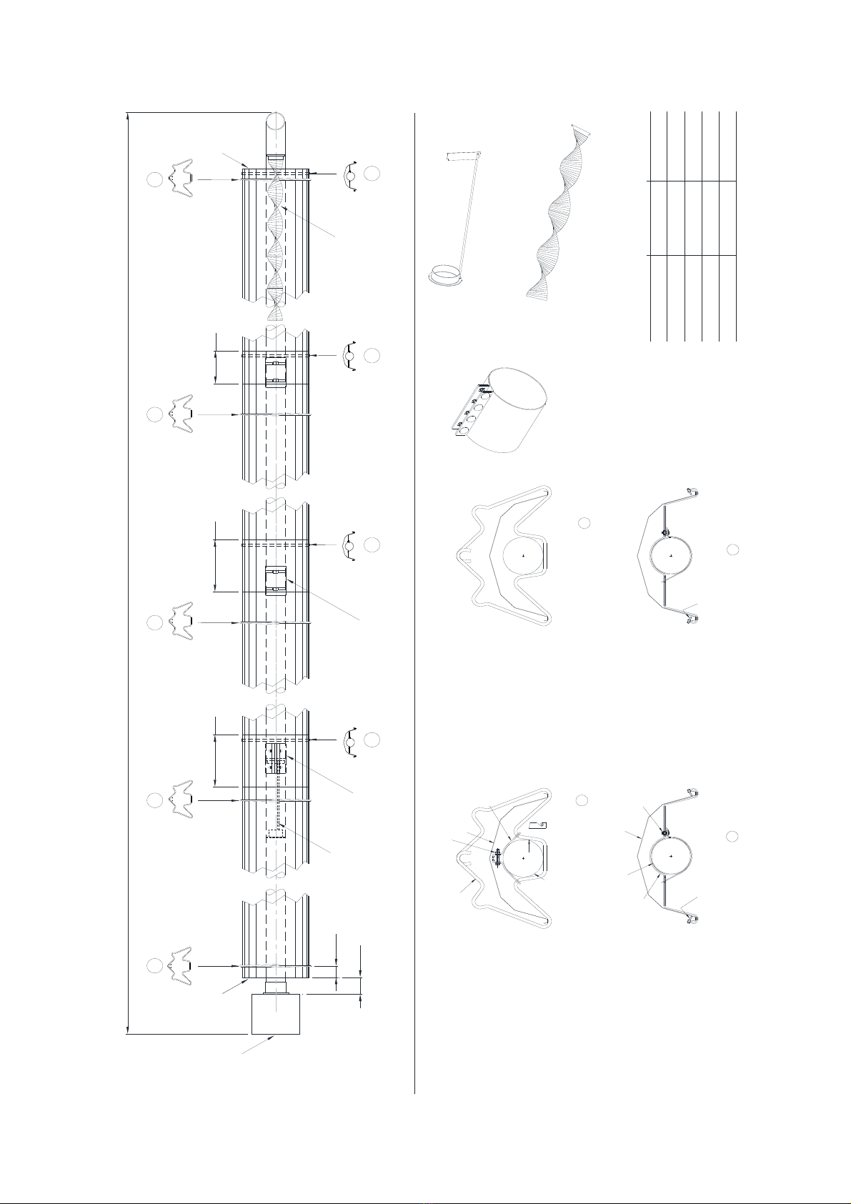
Figure 10. Heater Assembly: Model Linear 18-S30, 25-S30, 30-S30 and 38-S30.
MODEL NUMBER BTU/HR N.GAS
30S30 100,000/65,000
*38S30 123,500/95,000
REFLECTOR
TUBE
STRAP
RADIANT
TUBE
NUT &
BOLT
H
"A"
VIEWON "A"
TUBE
STRAP
RADIANT
TUBE
NUT & BOLT
SUSPENSION
BRACKET REFLECTOR
RADIANT
TUBE
TIGHTEN TO FIX REFLECTOR MIN 1/8" GAP TO ALLOW TO SLIDE
NUT &
BOLT
TUBE
STRAP
RADIANT
TUBE
NUT & BOLT
SUSPENSION
BRACKET REFLECTOR
FIRST SUSPENSION POINT TUBE
STRAP AGRICULTURAL DETAIL
F
FIXED REFLECTOR BRACKET
AGRICULTURAL DETAIL
H
FIRST SUSPENSION POINT
TUBE STRAP INDOOR DETAIL
TUBE
STRAP
REFLECTOR
G
TUBE AND REFLECTOR
SUSPENSION BRACKET
AGRICULTURAL DETAIL
S
SLIDING REFLECTOR BRACKET
AGRICULTURAL DETAIL
F
FIXED REFLECTOR BRACKET
INDOOR DETAIL
G
TUBE AND REFLECTOR SUSPENSION
BRACKET INDOOR DETAIL
S
SLIDING REFLECTOR BRACKET
INDOOR DETAIL
"A"
VIEW ON "A"
BTU/HR LP
125,000/95,000
6" REFLECTOR OVERLAP 6" REFLECTOR OVERLAP
END
CAPS
(OPTIONAL)
6"
4"
31'6½" NOMINAL OVERALL ASSEMBLED LENGTH
10' 3" REFLECTORS TYPICAL OF 3
END
CAPS
(OPTIONAL)
DISTANCE BETWEEN
SUSPENSION POINTS
NO TO EXCEED 12'
BURNER
H G G G
F FS
BURNER INSERT
SEE DETAIL
BURNER INSERT DETAIL PT. NO. 270489
NOTE: FOR MODELS 18/25/30 NAT GAS ONLY
TURBULATOR DETAIL PT. NO. 270566
* HIGH TEMP 4" COUPLER
STANDARD 4" COUPLER
25S30 80,000/60,000
*HT COUPLER
38 ONLY
COUPLER
100,000/65,000
80,000/60,000
NOTE: FOR MODELS 30/38 ONLY
18S30 60,000/45,000 60,000/45,000
20
Figure 11. Heater Assembly: Model Linear 18-S40, 25-S40, 30-S40, 38-S40 and 45-S40.
G
F
G GH
SS
COUPLERS
BURNER
END
CAPS
(OPTIONAL)
6"
4"
41'6½" NOMINAL OVERALL ASSEMBLED LENGTH
MODEL NUMBER BTU/HR N.GAS
30-S40 100,000/65,000
END
CAPS
(OPTIONAL)
DISTANCE BETWEEN
SUSPENSION POINTS
NO TO EXCEED 12'
*38-S40 123,500/95,000
*45-S40 150,000/100,000
10' 3" REFLECTORS
TYPICAL OF 4
6" REFLECTOR
OVERLAP
G
F
3" REFLECTOR
OVERLAP
TURBULATOR
SEE DETAIL
6" REFLECTOR
OVERLAP
REFLECTOR
TUBE
STRAP
RADIANT
TUBE
NUT &
BOLT
H
"A"
VIEW ON "A"
TUBE
STRAP
RADIANT
TUBE
NUT & BOLT
SUSPENSION
BRACKET REFLECTOR
RADIANT
TUBE
TIGHTEN TO FIX REFLECTOR MIN 1/8" GAP TO ALLOW TO SLIDE
NUT &
BOLT
TUBE
STRAP
RADIANT
TUBE
NUT & BOLT
SUSPENSION
BRACKET REFLECTOR
FIRST SUSPENSION POINT TUBE
STRAP AGRICULTURAL DETAIL
F
FIXED REFLECTOR BRACKET
AGRICULTURAL DETAIL
H
FIRST SUSPENSION POINT
TUBE STRAP INDOOR DETAIL
TUBE
STRAP
REFLECTOR
G
TUBE AND REFLECTOR
SUSPENSION BRACKET
AGRICULTURAL DETAIL
S
SLIDING REFLECTOR BRACKET
AGRICULTURAL DETAIL
F
FIXED REFLECTOR BRACKET
INDOOR DETAIL
G
TUBE AND REFLECTOR SUSPENSION
BRACKET INDOOR DETAIL
S
SLIDING REFLECTOR BRACKET
INDOOR DETAIL
"A"
VIEW ON "A"
BTU/HR LP
125,000/95,000
150,000/100,000
BURNER INSERT
SEE DETAIL
BURNER INSERT DETAIL PT. NO. 270489
NOTE: FOR MODELS 18/25/30 NAT GAS ONLY
TURBULATOR DETAIL PT. NO. 270566
NOTE: FOR MODEL 45 ONLY
*HT COUPLER
MODELS 38/45 ONLY
* HIGH TEMP 4" COUPLER
STANDARD 4" COUPLER
25-S40 80,000/60,000
100,000/65,000
80,000/60,000
18-S40 60,000/45,000 60,000/45,000
Table of contents
Popular Heater manuals by other brands


Philips
Philips HD3455/77 operating instructions

Sun Heat
Sun Heat SH42 owner's manual

L.B. White
L.B. White CV100 Owner's manual and instructions

Harry Taylor
Harry Taylor HT2000 Installation & servicing manual

TPI
TPI CV Series Installation instructions and accessories

Dyna-Glo
Dyna-Glo LPC25 Series User's installation, operation and maintenance manual