Juwent AGE-1-3 User guide

AGE
ELECTRIC HEATING UNIT
Szymański, Nowakowski General Partnership
31 Lubelska Str., 08-500 Ryki
phone +48 81 883 56 00, fax +48 81 883 56 09
POLAND
I. CONTACTS
II. ORIGINAL INSTRUCTION MANUAL
III. WARRANTY TERMS AND CONDITIONS
IV. UNIT STARTUP REPORT
V. INSPECTION AND MAINTENANCE DOCUMENT
VI. SERVICE NOTIFICATION
Please read this instruction manual carefully before beginning any work.
RYKI 2015
ISSUE 1 EN

2www.juwent.com.pl
I. CONTACTS
Szymański, Nowakowski General Partnership
31 Lubelska Str., 08-500 Ryki
phone +48 81 883 56 00, fax +48 81 883 56 09
POLAND
Export department
mob.+48 502 087 841
mob.+48 664 465 243

3www.juwent.com.pl
ELECTRIC HEATING UNITS
AGE size 1÷6
II. ORIGINAL INSTRUCTION MANUAL

4www.juwent.com.pl
TABLE OF CONTENTS
1. INTENDED USE 5
2. DESIGNATIONS 5
3. DEVICE DESCRIPTION 5
4. TECHNICAL DATA 6
5. TRANSPORT 6
6. SAFETY RECOMMENDATIONS 7
7. INSTALLATION 8
8. ELECTRICAL INSTALLATION 9
9. AUTOMATICS 10
10. DEVICE COMMISSIONING 11
11. REPAIRS, MAINTENANCE AND DECOMMISSIONING 12
12. TROUBLESHOOTING 12
13. INFORMATION 12

5www.juwent.com.pl
1. INTENDED USE
AGE heating units with axial fans are intended for heating both living spaces and oor areas.
Intended use:
»basic heating and reheating for large rooms, used temporarily (e.g. production oors, arenas,
exhibition halls, storerooms, churches, conference rooms, garages);
»heating rooms on building sites, heating and drying, winter season works;
»protection against freezing, prevention of low temperatures and losses in rooms with freezing
hazard (e.g. greenhouses, beverage storerooms).
2. DESIGNATIONS
Electric heating and ventilation unit AGE- -
Size 1; 2; 3; 4; 5; 6
Heater power 3, 6, 9, 12, 18, 27, 36 kW
3. DEVICE DESCRIPTION
AGE unit series include 6 sizes (Fig. 1).
The unit features:
»axial fan (1);
»heating system (2) heating elements with rolled aluminium radiator in a self clamping sieve.
Leads of connected heaters with rigid bridges and cables included with the control elements. I,
II, and III row heating systems available.
»control unit (3) fan switching, power setting with: switch (standard - manual) or temperature
regulator (automatic - optional) depending on room air temperature.
The control system features an additional thermostat for heating elements preventing
exceeding heater threshold values;
»housing with handles and feet (4);
»outlet grille (5);
Rys. 1 Unit design

6www.juwent.com.pl
4. TECHNICAL DATA
A group connection of heaters allows selection of power setting. The units are available with the
following power settings:
»single stage: AGE-1 [3kW];
»two stages AGE-2 [3, 6 kW], AGE-3 [3, 9 kW];
»three stages AGE-4 [6, 9, 12 kW], AGE-5 [6, 12, 18 kW], AGE-6 [9, 18, 27 kW].
Basic technical data and dimensions (Table I).
Unit size a
[mm]
b
[mm]
h
[mm]
Lmin
[mm]
U
heater
[V]
I
heater
[A]
I
heater
[kW]
Air ow
[m3/h]
n
[rpm]
P
fan
[W]
U
fan
[V]
Weight
[kg]
AGE-1-3 502 300 245 100 400 4,5 3450 1300 32 120 13
AGE-2-6 502 365 245 125 400 9 6 850 1300 46 230 16
AGE-3-9 502 465 255 150 400 13 9 1450 1300 64 230 19
AGE-4-12 502 465 255 150 400 17 12 1450 1300 64 230 21
AGE-5-18 502 515 325 160 400 27 18 2100 1400 120 230 28
AGE-6-27 502 575 375 180 400 39 27 2900 1400 200 230 34
Lmin – minimum unit distance from the wall.
Units are tted with 10 mm high feets.
Unit thermal power and air temperature increase (Table II).
Unit size
Heater stage
I II III
P
[kW]
Dt
[OC]
P
[kW]
Dt
[OC]
P
[kW]
Dt
[OC]
AGE-1-3 319 - - - -
AGE-2-6 310 6 21 - -
AGE-3-9 6 12 9 18 - -
AGE-4-12 6 12 9 18 12 24
AGE-5-18 6 8 12 17 18 25
AGE-6-27 9 9 18 18 27 25
Operating noise level
Unit size Noise [dB(A)] from 1 m
AGE-1-3 51
AGE-2-6 53
AGE-3-9 61
AGE-4-12 61
AGE-5-18 61
AGE-6-27 63
5. TRANSPORT
The units are delivered ready to use with a protective lm packaging. The packaging is suitable for
any type of transport provided that the units are protected against precipitation and impurities.
Inspect the packages delivered by the forwarding companies (marking on the packaging).

7www.juwent.com.pl
Notify the forwarding company immediately in case of any transport damages.
Missing parts and transport damages can only be claimed from the transport insurance, if the
damage is acknowledged by the forwarding company.
6. SAFETY RECOMMENDATIONS
Use the electric unit in compliance with this User Manual.
Commissioning, installation, connection, inspections and repairs shall be carried out by
an authorised electrician.
Disconnect power supply before any repairs or maintenance works.
Protect the unit against moisture and do not use wet cloths for cleaning.
Use the device in working order only, disconnect power supply in case of any faults.
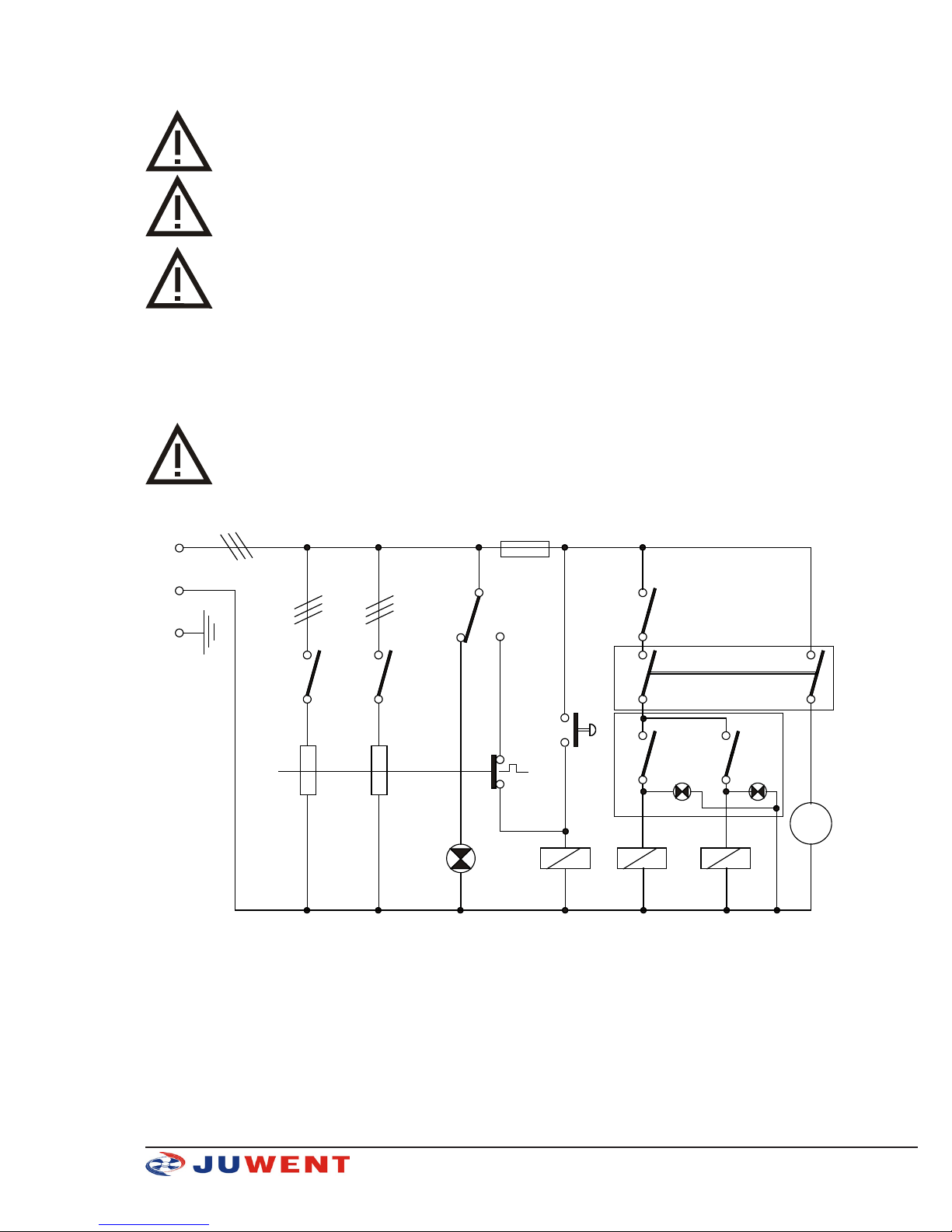
Check the electrical system before connecting the heating unit.
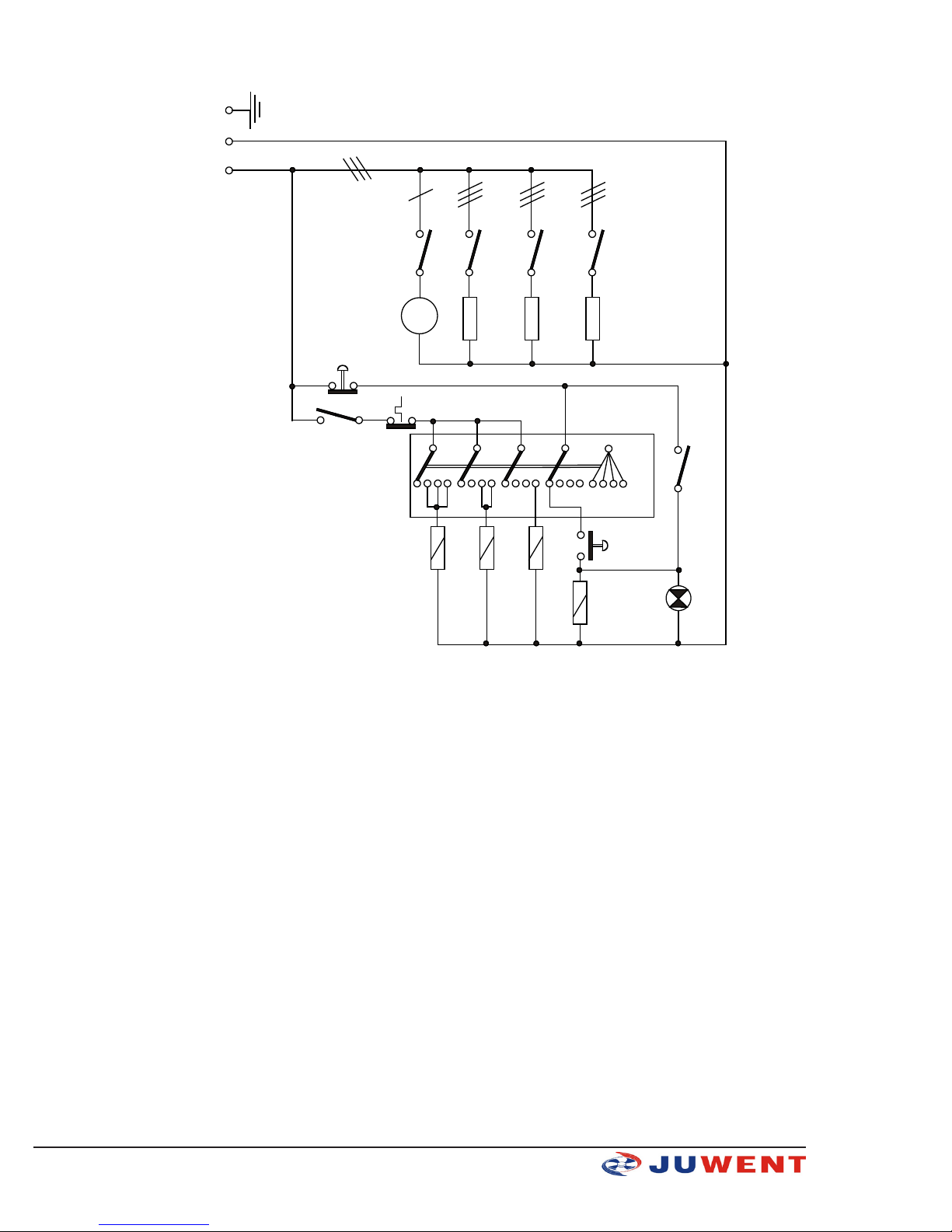
The unit must be earthed.
The unit is connected to the electrical system with residual device and protective
terminal (earth).
The thermostat preventing overheating must be connected in the heating unit control
system.
Do not switch on the unit without the fan running.
Potential free state is obtained by disconnecting the power supply cable from the
socket.
Due to its design, the device does not emit any hazardous radiation.
Important note! Any installation or use of the fan not in accordance with the instruction
manual may cause the fan damage and voids the warranty.
Despite the fact that the device has been designed and manufactured in accordance with the
standards valid as for the moment of the manufacture start, probability of injury and damage
to health when using the device is unavoidable. This probability is related to frequency of using,
cleaning and repairing the device, presence of persons within the danger area, and not respecting
the safety rules as set out in the instruction.

8www.juwent.com.pl
Severity of the bodily injury and deterioration of health is dependant on numerous conditions which
can be foreseen partially only by considering them when designing the device and by providing
descriptions and warnings in the instruction manual.
Therefore residual risk is present if recommendations and instructions are not respected by the
operator.
7. INSTALLATION
AGE units (sizes 1 to 6) are installed on walls or structural columns in the distance between the unit
and the fan air inlet equal to 0.5x fan diameter Lmin (Table I). Fig. 2 and 3 shows layout and functions
of control elements.
b
a
c
AGE 1÷3
Fig. 2. Layout and functions of control elements.
a - control button: Fan I - on, O - off,
a - control button: O - heating unit off, position 1 or 2 heating stage selection,
c - button (red): maximum heating element temperature threshold alarm reset;
d
b
a
c
AGE 4÷6
Fig. 3. Layout and functions of control elements.
a - lamp: fan operation, lights with (START) (b) pressed,
b - button - START (green): fan ON,
c - button - STOP (red): unit OFF,
d - switch: position 0 - heating OFF, position 1, 2 or 3 - heating stage selection,

9www.juwent.com.pl
8. ELECTRICAL INSTALLATION
Electric unit electrical system and wiring must be carried out in accordance with current
standards and regulations.
Unit may only be connected by a certied electrician familiar with this User Manual.
Before installation, make sure the mains voltage and frequency correspond to the values
specied on a data plate. Otherwise DO NOT connect the unit.
The electric units are supplied with (3~400V/50Hz) by the main switchgear with a main switch,
residual device and a protective terminal (earth). Allow for the disconnecting switch (distance
between the contacts of all poles >3 mm) directly by the unit. The cross-sections of power cable
depend on the unit power and terminal types in accordance with power supplier requirements.
Power cable is terminated with a plug for sockets with earth pin.
Connect the unit in accordance with the wiring diagrams in the operation and installation
manual.
Fig. 4 and 5 show example wiring and control diagrams.
LIST OF COMPONENTS:
K - relay W1 - switch: W34.2; 16A/250V
W2 - heating power switch: W2.6; 16A/250V PZ - control button: FT22; 380V/1.6A
Rd - thermal safety device M - motor
L - LED G1,G2 - heating elements: 1000W,2000W/230V
S1,S2 - heating element contactors
Fig. 4 Wiring diagram AGE 1-3, AGE 2-6, AGE 3-9
K
L
W1
PZ
M
S1
L
N
PE
K
W2
S2
RD
K
F
G1 G2
S1 S2

10 www.juwent.com.pl
LIST OF COMPONENTS:
PZ,PW - control button: FT22; 380V/1.6A L- LED
Rd - thermal safety device M - motor
S1,S2,S3,SW - heating element contactors PP - power mode selector
G1,G2,G3 - heating elements: 1000W,2000W/230V
Fig. 5 Wiring diagram AGE 4-12, AGE 5-18, AGE 6-27
9. AUTOMATICS
The heating unit is tted with a THERMOSTAT of the heater element limiting and monitoring outlet
air temperature in case of air ow disturbances (e.g. fan failure). Thermostat temperature setting
range is 0OC to 100OC with constant hysteresis of 3OC. Monitoring temperature is factory set at 80OC,
and limit temperature is always higher by 20ºC than the preset temperature.Jako dodatkowa opcja,
aparaty mogą być wyposażone w następujące elementy automatyki:
L
PW
M
L
N
PE
RD
G1 G2
S1 S2
G3
S3SW
SW
S1 S2 S3
SW
PZ
0 1 2 3
PP
SW

11www.juwent.com.pl
The units may also be tted with the following components:
1. ROOM THERMOSTAT (ON-OFF) with temperature setting dial (size AGE-1, AGE-2, AGE-3),
maintaining preset room temperature.
2. TEMPERATURE CONTROLLER (two-stage) - room temperature control and adjustment. (Sizes
AGE-4 and higher).
3. TIMER: programming heating unit operation time.
An additional wiring diagram is included with the optional equipment.
10. DEVICE COMMISSIONING
Read the User Manual;
1. Check additional safety devices;
2. Check supply voltage with the data plate;
3. Plug the power supply cable to the socket with earth plug;
4. Switch on the heating unit power supply.
Next steps depend on AGE unit size:
AGE-1, AGE-2, AGE-3 units:
Before start-up:
»set (b) to 0.
»press (a); fan ON.
»press (b) to switch on the heating unit; button will light.
After use:
»press (b) to switch off the heater;
»press (a) to switch off the unit.
The fan will continue to rotate for 15-20 seconds. The unit will switch off automatically after the
heater element temperature is reduced.
In case of voltage decay or other interferences:
»press (c)
»restart the unit
AGE-4, AGE-5, AGE-6 units:
Before start-up:
»set (d) to 0;
»press (b) (green); green lamp will light and the fan is ON;
»use switch (d) to switch on the heating elements 1, 2 or 3, yellow lamp will light
The fan will automatically start for approx. 15 - 20 seconds after the unit is plugged in.
The fan will switch off automatically.
After use:
»use switch (d) to switch off the heating elements, position 0;
»press (c) (red) to switch off the unit.
The fan will continue to rotate for 15-20 seconds. The unit will switch off automatically after the
heater element temperature is reduced.

12 www.juwent.com.pl
11. REPAIRS, MAINTENANCE AND DECOMMISSIONING
Disconnect power supply before any repairs or maintenance works.
Depending on air quality, at least once a year check the heater for impurities. Clean with compressed
air, if needed.
The impurities reduce air output and heating power.
After the decommissioning utilise in a special waste disposal plant.
12. TROUBLESHOOTING
Unit does not start:
»no power supply, safety device activated;
»insufcient or reduced air ow (fan failure, heater dirty).
Low temperature at unit output:
»low voltage (system overload);
»heater dirty (clean the heater, see repair and maintenance section);
»check heating power switch for maximum setting.
If the failure still persists, contact Juwent service department or a qualied tter.
Description of
malfunction Possible causes of malfunction Measures of prevention/removal
excessive unit no-
ise
incorrect distance from wall or ceiling maintain required distance
incorrect power supply parameters use with correct mains and device parameters
air outlet limited with outlet grille shutters keep the outlet grille shutters open at high speed obro-
towej wentylatora
fan vibrations, rubbing between impeller and en-
closure check installation of fan and other components
fan misaligned at the support plate
fan not working
incorrect connections
check and correct:
1) connections as per diagrams
2) terminal connections
3) mains parameters
incorrect power supply parameters (less than three
phases for three-phase motors)
fan motor failure
fan control elements failure
13. INFORMATION
As to all issues concerning the electric heatnig units contact JUWENT Production Plant or our
Representatives

13www.juwent.com.pl
III. WARRANTY TERMS AND CONDITIONS
1. JUWENT Szymański, Nowakowski General Partnership, headquartered in Ryki at 31 Lubelska Str., hereinafter referred to as the
Warrantor, grants the Customer a warranty of proper operation of the unit with reservation of the requirement of its use in accordance
with the conditions determined in the instruction manual and the terms and conditions specied below.
2. The warranty has been granted for a period of 24 months from the purchase date demonstrated in this warranty document with
a possibility of its special extension according to a separate agreement and specied in the Special Warranty Terms and Conditions.
3. The warranty covers the removal of technical defects of the unit arisen as a result of its use in accordance with the instruction
manual, revealed within the warranty period. The warranty provisions are valid in the territory of the Republic of Poland.
4. By virtue of the granted warranty the Warrantor is not liable for the loss of expected prots and costs resulting from a periodical
impossibility of the use of the unit incurred by the Customer.
5. To realize the Customer’s rights resulting from the warranty it is required to deliver the claimed unit with the warranty document
to the Warrantor at his expense.
6. The claimer delivers the unit in an original factory packing, in case there is no factory packing the claimed unit should be delive-
red by the Customer for the repair in a way ensuring a safe transport. The risk of accidental damage of the unit during the transport
burdens always the party that dispatches the parcel.
7. The defects revealed with the warranty period will be removed by the Warrantor free of charge. A method selection of the reali-
zation of obligations resulting from the warranty granted to the Customer belongs to the Warrantor that may remove a defect by the
repair or the replacement of the damaged subassembly or by the replacement of the unit. The property of the unit withdrawn from
service and / or defective subassemblies is transferred to the Warrantor.
8. The warranty is extended by a period for which the Customer has been deprived of a possibility to use the unit.
9. The Warrantor will make efforts that the repair is executed without further delay within the time-limit of up to 14 working days
from the delivery date of the unit. In reasonable cases of which the Customer will be informed by the Warrantor, this time-limit may
be extended, e.g. by the time of provision import or when there is a necessity to execute an expertise or laboratory tests in specialized
institutions.
10. The Warrantor is liable exclusively for the defects inherent in the sold unit. The damages arisen after its sale for other reasons are
not covered by the warranty, in particular:
a) mechanical damages (including also damages caused by microparticles occurring in the working environment of the unit),
thermal damages, chemical damages and aleatory damages or damages caused by the atmospheric factors,
b) damages occurred as a result of non-observance of typical rules or the rules required by the instruction manual related to the
operation and mounting of the unit or the use of the unit against the intended use and other damages caused by the Customer’s
activity or omission,
c) damages being a result of defective operation of the system in which the unit has been built or used,
d) damages occurred as a result of non-execution of the actions to which the Customer has been obliged in accordance with the
instruction manual, e.g. periodical cleaning, maintenance, adjustment, etc.,
e) damages occurred due to the use of materials or parts subject to a normal operational wear other than the materials recom-
mended by the Warrantor in the instruction manual,
f) damages being a result of use of power supply of the unit (of the system in which this unit functions) incompliant with the
standard, and in case the unit is also supplied with water, damages being a result of use of water (supply water and / or boiler
water) with parameters other than the parameters foreseen in the valid standard (PN-93/C-04607),
g) damages occurred as a result of operation and / or maintenance of the unit in a way incompliant with the instruction manual
and / or executed by the unauthorized persons.
11. The warranty does not cover as well:
a) activities executed by the Customer in accordance with the recommendations included the instruction manual of the unit within
the framework of normal maintenance and inspections,
b) travel and work costs of the Warrantor’s service or an entity delegated by the Warrantor in case when a warrant call turns out
to be groundless.
12. An annotation made by a trained employee in the Inspection and Maintenance Document of the unit is a conrmation of time-
-limit holding and range of activities foreseen for the maintenance of the unit.
13. The Warrantor is not liable for damages incurred by the Customer or third parties caused the run of the unit occurred in particular
as a result of non-observance of the afore-mentioned terms and conditions by the Customer.
14. In case the service works are executed by the Warrantor at the place where the unit is mounted, the Customer will make available
a free access to the rooms where the units are located to the Warrantor.
15. In case the units are mounted at the height making an access from the oor surface impossible, the Customer will ensure the
scaffolding compliant with the OHS regulations or mobile lifting platforms and vertical transport equipment.
16. The equipment from the electric and / or hydraulic system is disassembled by the Customer.
17. The claims should be lodged at the Warrantor’s address in writing / by fax / email using a service notication form.
18. The Warrantor refuses to execute the warranty activities (periodical service works or repair) in case the price for the unit or pre-
vious service work is not paid for the benet of the Warrantor.
DATE OF SALE STAMP AND SIGNATURE
Special Warranty Terms and Conditions:
Warranty period extension up to ........... months.
Other:
STAMP AND SIGNATURE

14 www.juwent.com.pl
TYPE OF UNIT:
FACTORY NUMER:
YEAR OF PRODUCTION:
IV. UNIT STARTUP REPORT
Date of
startup
Executor of startup
stamp / name and signature
Motor
current
[A]
User’s representative
stamp / name and signature Remarks
V. INSPECTION AND MAINTENANCE DOCUMENT
Date of
inspection
Executor of inspection
stamp / name and signature Service activity range Remarks
* Inspection of the unit in accordance with the section “Repair and Maintenance” in the instruction manual

15www.juwent.com.pl
VI. SERVICE NOTIFICATION
Date:
Notication type WARRANTY POST-WARRANTY PAID
Unit’s user (name)
Contact person
User’s address
Phone, fax. and email
Type of unit
Factory No.
Year of production
Startup executed by
Description of defect:
NOTE: AFTER COPYING AND FILLING IN SEND THE NOTIFICATION BY FAX OR EMAIL TOGETHER WITH A
COPY OF THE STARTUP REPORT.
JUWENT Company accepts notications lled legibly and completely.
When the lodged claim is not justied, the claimer will be burdened with service costs.
Date of warranty issue Order No. (company’s stamp)
......................................................... ...........................
This manual suits for next models
5
Table of contents
Other Juwent Heater manuals
Popular Heater manuals by other brands

Harvia
Harvia KV30 Instructions for installation and use

Argo
Argo HIFAN operating instructions

Tutco-Farnam
Tutco-Farnam Heat Torch 150 quick guide

HEATFun
HEATFun PRO LINE Installation and user instructions

Saunatec
Saunatec 1106-105 Installation and operating instructions

Feider Machines
Feider Machines FCD37KW-1 instruction manual